length CHRYSLER VOYAGER 2005 Service Manual
[x] Cancel search | Manufacturer: CHRYSLER, Model Year: 2005, Model line: VOYAGER, Model: CHRYSLER VOYAGER 2005Pages: 2339, PDF Size: 59.69 MB
Page 54 of 2339

(4) Remove the bolts fastening the power steering
cooler to the front suspension cradle crossmember
reinforcement (Fig. 21).
(5) Remove the lower control arm rear bushing
retainer bolts located on each side of each lower con-
trol arm rear bushing.
NOTE: The bolts fastening the cradle crossmember
reinforcement are of three different thread sizes.
Note the location of the various sizes.
(6) Remove the bolts attaching the cradle cross-
member reinforcement to the front suspension cradle
crossmember (Fig. 22). Remove the 2 bolts fastening
the reinforcement and rear of cradle crossmember to
the body of the vehicle. Remove the reinforcement.
(7) Remove the pivot bolt attaching the front bush-
ing of the lower control arm to the front suspension
cradle crossmember.
(8) Remove the lower control arm.
DISASSEMBLY
DISASSEMBLY - LOWER CONTROL ARM
(REAR BUSHING - STANDARD)
(1) Remove the lower control arm from the front
suspension cradle. (Refer to 2 - SUSPENSION/
FRONT/LOWER CONTROL ARM - REMOVAL)
(2) Mount the lower control arm in a visewithout
using excessive clamping force.(3) Using a sharp knife (such as a razor), slit the
bushing lengthwise (Fig. 23) to allow its removal
from the lower control arm (Fig. 23).
(4) Remove the bushing from the lower control
arm.
DISASSEMBLY - LOWER CONTROL ARM
(REAR BUSHING - HYDRO)
(1) Remove the lower control arm from the front
suspension cradle. (Refer to 2 - SUSPENSION/
FRONT/LOWER CONTROL ARM - REMOVAL)
(2) Mount the lower control arm in a visewithout
using excessive clamping force.
(3) Install Remover, Special Tool 8460, on hydro-
bushing as shown (Fig. 24). Removal Pin, Special
Tool 8460±3, must extend though hole in center of
bushing rear.
(4) Tighten forcing screw of Bridge (Special Tool
8460±1), removing bushing from lower control arm.
Fig. 21 Power Steering Cooler
1 - CRADLE CROSSMEMBER REINFORCEMENT
2 - POWER STEERING COOLER
Fig. 22 Cradle Crossmember Reinforcement
Attachment
1 - STEERING GEAR
2 - RIGHT LOWER CONTROL ARM
3 - LEFT LOWER CONTROL ARM
4 - CRADLE CROSSMEMBER REINFORCEMENT
5 - REAR CRADLE CROSSMEMBER ISOLATOR BUSHING
6 - STABILIZER BAR
7 - CRADLE CROSSMEMBER
RSFRONT SUSPENSION2-13
LOWER CONTROL ARM (Continued)
Page 65 of 2339
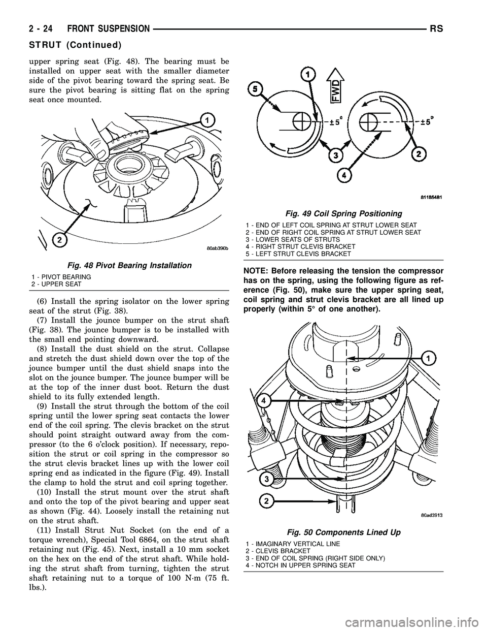
upper spring seat (Fig. 48). The bearing must be
installed on upper seat with the smaller diameter
side of the pivot bearing toward the spring seat. Be
sure the pivot bearing is sitting flat on the spring
seat once mounted.
(6) Install the spring isolator on the lower spring
seat of the strut (Fig. 38).
(7) Install the jounce bumper on the strut shaft
(Fig. 38). The jounce bumper is to be installed with
the small end pointing downward.
(8) Install the dust shield on the strut. Collapse
and stretch the dust shield down over the top of the
jounce bumper until the dust shield snaps into the
slot on the jounce bumper. The jounce bumper will be
at the top of the inner dust boot. Return the dust
shield to its fully extended length.
(9) Install the strut through the bottom of the coil
spring until the lower spring seat contacts the lower
end of the coil spring. The clevis bracket on the strut
should point straight outward away from the com-
pressor (to the 6 o'clock position). If necessary, repo-
sition the strut or coil spring in the compressor so
the strut clevis bracket lines up with the lower coil
spring end as indicated in the figure (Fig. 49). Install
the clamp to hold the strut and coil spring together.
(10) Install the strut mount over the strut shaft
and onto the top of the pivot bearing and upper seat
as shown (Fig. 44). Loosely install the retaining nut
on the strut shaft.
(11) Install Strut Nut Socket (on the end of a
torque wrench), Special Tool 6864, on the strut shaft
retaining nut (Fig. 45). Next, install a 10 mm socket
on the hex on the end of the strut shaft. While hold-
ing the strut shaft from turning, tighten the strut
shaft retaining nut to a torque of 100 N´m (75 ft.
lbs.).NOTE: Before releasing the tension the compressor
has on the spring, using the following figure as ref-
erence (Fig. 50), make sure the upper spring seat,
coil spring and strut clevis bracket are all lined up
properly (within 5É of one another).
Fig. 48 Pivot Bearing Installation
1 - PIVOT BEARING
2 - UPPER SEAT
Fig. 49 Coil Spring Positioning
1 - END OF LEFT COIL SPRING AT STRUT LOWER SEAT
2 - END OF RIGHT COIL SPRING AT STRUT LOWER SEAT
3 - LOWER SEATS OF STRUTS
4 - RIGHT STRUT CLEVIS BRACKET
5 - LEFT STRUT CLEVIS BRACKET
Fig. 50 Components Lined Up
1 - IMAGINARY VERTICAL LINE
2 - CLEVIS BRACKET
3 - END OF COIL SPRING (RIGHT SIDE ONLY)
4 - NOTCH IN UPPER SPRING SEAT
2 - 24 FRONT SUSPENSIONRS
STRUT (Continued)
Page 98 of 2339

DIFFERENTIAL & DRIVELINE
HALF SHAFT - FRONT
TABLE OF CONTENTS
page page
HALF SHAFT - FRONT
DESCRIPTION..........................1
DIAGNOSIS AND TESTING - HALF SHAFT.....1
REMOVAL.............................2
INSTALLATION..........................4
SPECIFICATIONS - HALF SHAFT - FRONT....6CV BOOT - INNER
REMOVAL.............................6
INSTALLATION..........................7
CV BOOT - OUTER
REMOVAL.............................10
INSTALLATION.........................11
HALF SHAFT - FRONT
DESCRIPTION
All vehicles use an unequal length half shaft sys-
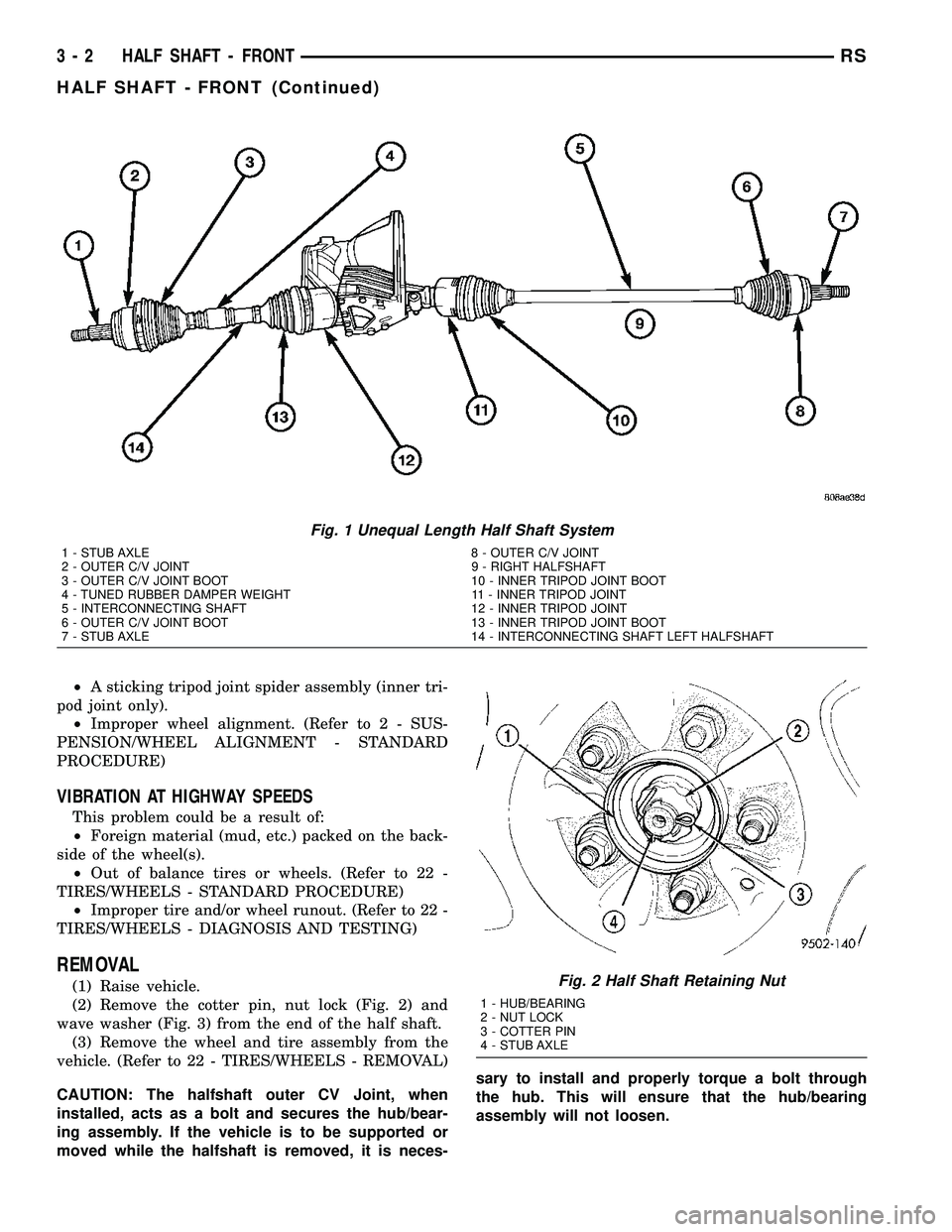
tem (Fig. 1).
The left half shaft uses a tuned rubber damper
weight. When replacing the left half shaft, be sure
the replacement half shaft has the same damper
weight as the original.
All half shaft assemblies use the same type of
inner and outer joints. The inner joint of both half
shaft assemblies is a tripod joint, and the outer joint
of both half shaft assemblies is a Rzeppa joint. Both
tripod joints and Rzeppa joints are true constant
velocity (CV) joint assemblies. The inner tripod joint
allows for the changes in half shaft length through
the jounce and rebound travel of the front suspen-
sion.
On vehicles equipped with ABS brakes, the outer
CV joint is equipped with a tone wheel used to deter-
mine vehicle speed for ABS brake operation.
The inner tripod joint of both half shafts is splined
into the transaxle side gears. The inner tripod joints
are retained in the side gears of the transaxle using
a snap ring located in the stub shaft of the tripod
joint. The outer CV joint has a stub shaft that is
splined into the wheel hub and retained by a steel
hub nut.
DIAGNOSIS AND TESTING - HALF SHAFT
VEHICLE INSPECTION
(1) Check for grease in the vicinity of the inboard
tripod joint and outboard CV joint; this is a sign of
inner or outer joint seal boot or seal boot clamp dam-
age.
NOISE AND/OR VIBRATION IN TURNS
A clicking noise and/or a vibration in turns could
be caused by one of the following conditions:
²Damaged outer CV or inner tripod joint seal
boot or seal boot clamps. This will result in the loss
and/or contamination of the joint grease, resulting in
inadequate lubrication of the joint.
²Noise may also be caused by another component
of the vehicle coming in contact with the half shafts.
CLUNKING NOISE DURING ACCELERATION
This noise may be a result of one of the following
conditions:
²A torn seal boot on the inner or outer joint of the
half shaft assembly.
²A loose or missing clamp on the inner or outer
joint of the half shaft assembly.
²A damaged or worn half shaft CV joint.
SHUDDER OR VIBRATION DURING ACCELERATION
This problem could be a result of:
²A worn or damaged half shaft inner tripod joint.
RSDIFFERENTIAL & DRIVELINE3-1
Page 99 of 2339
²A sticking tripod joint spider assembly (inner tri-
pod joint only).
²Improper wheel alignment. (Refer to 2 - SUS-
PENSION/WHEEL ALIGNMENT - STANDARD
PROCEDURE)
VIBRATION AT HIGHWAY SPEEDS
This problem could be a result of:
²Foreign material (mud, etc.) packed on the back-
side of the wheel(s).
²Out of balance tires or wheels. (Refer to 22 -
TIRES/WHEELS - STANDARD PROCEDURE)
²Improper tire and/or wheel runout. (Refer to 22 -
TIRES/WHEELS - DIAGNOSIS AND TESTING)
REMOVAL
(1) Raise vehicle.
(2) Remove the cotter pin, nut lock (Fig. 2) and
wave washer (Fig. 3) from the end of the half shaft.
(3) Remove the wheel and tire assembly from the
vehicle. (Refer to 22 - TIRES/WHEELS - REMOVAL)
CAUTION: The halfshaft outer CV Joint, when
installed, acts as a bolt and secures the hub/bear-
ing assembly. If the vehicle is to be supported or
moved while the halfshaft is removed, it is neces-sary to install and properly torque a bolt through
the hub. This will ensure that the hub/bearing
assembly will not loosen.
Fig. 1 Unequal Length Half Shaft System
1 - STUB AXLE 8 - OUTER C/V JOINT
2 - OUTER C/V JOINT 9 - RIGHT HALFSHAFT
3 - OUTER C/V JOINT BOOT 10 - INNER TRIPOD JOINT BOOT
4 - TUNED RUBBER DAMPER WEIGHT 11 - INNER TRIPOD JOINT
5 - INTERCONNECTING SHAFT 12 - INNER TRIPOD JOINT
6 - OUTER C/V JOINT BOOT 13 - INNER TRIPOD JOINT BOOT
7 - STUB AXLE 14 - INTERCONNECTING SHAFT LEFT HALFSHAFT
Fig. 2 Half Shaft Retaining Nut
1 - HUB/BEARING
2 - NUT LOCK
3 - COTTER PIN
4 - STUB AXLE
3 - 2 HALF SHAFT - FRONTRS
HALF SHAFT - FRONT (Continued)
Page 136 of 2339
master cylinder reservoir from completely draining
out.
(3) Disconnect the brake fluid flex hose from the
caliper assembly and remove it from the vehicle.
CAUTION: Do not use excessive force when clamp-
ing caliper in vise. Excessive vise pressure will
cause bore distortion.
(4) Mount the caliper in a vise equipped with pro-
tective jaws.
(5) Remove the piston dust boot from the caliper
and discard.
NOTE: Do not use a screw driver or other metal tool
for seal removal. Using such tools can scratch the
bore or leave burrs on the seal groove edges.
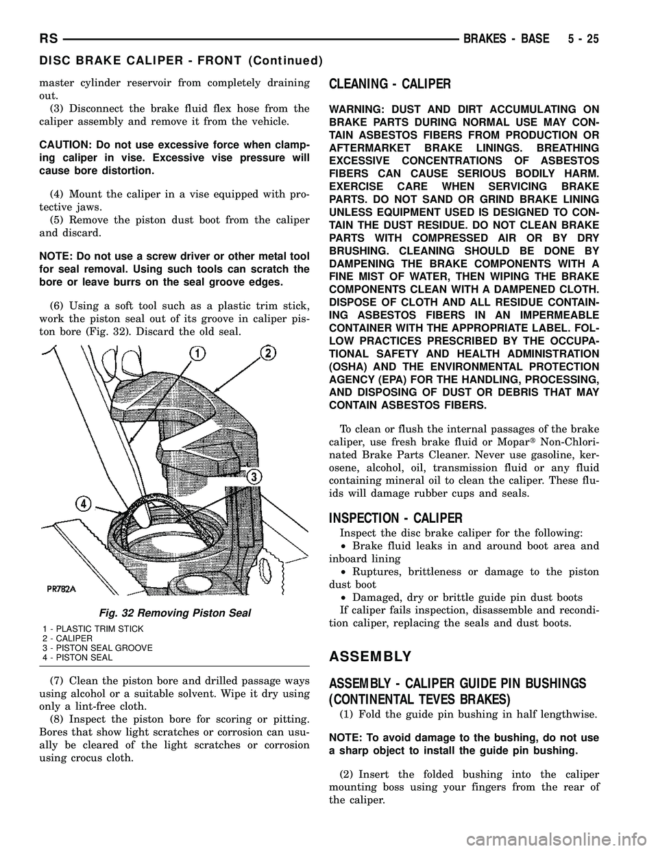
(6) Using a soft tool such as a plastic trim stick,
work the piston seal out of its groove in caliper pis-
ton bore (Fig. 32). Discard the old seal.
(7) Clean the piston bore and drilled passage ways
using alcohol or a suitable solvent. Wipe it dry using
only a lint-free cloth.
(8) Inspect the piston bore for scoring or pitting.
Bores that show light scratches or corrosion can usu-
ally be cleared of the light scratches or corrosion
using crocus cloth.CLEANING - CALIPER
WARNING: DUST AND DIRT ACCUMULATING ON
BRAKE PARTS DURING NORMAL USE MAY CON-
TAIN ASBESTOS FIBERS FROM PRODUCTION OR
AFTERMARKET BRAKE LININGS. BREATHING
EXCESSIVE CONCENTRATIONS OF ASBESTOS
FIBERS CAN CAUSE SERIOUS BODILY HARM.
EXERCISE CARE WHEN SERVICING BRAKE
PARTS. DO NOT SAND OR GRIND BRAKE LINING
UNLESS EQUIPMENT USED IS DESIGNED TO CON-
TAIN THE DUST RESIDUE. DO NOT CLEAN BRAKE
PARTS WITH COMPRESSED AIR OR BY DRY
BRUSHING. CLEANING SHOULD BE DONE BY
DAMPENING THE BRAKE COMPONENTS WITH A
FINE MIST OF WATER, THEN WIPING THE BRAKE
COMPONENTS CLEAN WITH A DAMPENED CLOTH.
DISPOSE OF CLOTH AND ALL RESIDUE CONTAIN-
ING ASBESTOS FIBERS IN AN IMPERMEABLE
CONTAINER WITH THE APPROPRIATE LABEL. FOL-
LOW PRACTICES PRESCRIBED BY THE OCCUPA-
TIONAL SAFETY AND HEALTH ADMINISTRATION
(OSHA) AND THE ENVIRONMENTAL PROTECTION
AGENCY (EPA) FOR THE HANDLING, PROCESSING,
AND DISPOSING OF DUST OR DEBRIS THAT MAY
CONTAIN ASBESTOS FIBERS.
To clean or flush the internal passages of the brake
caliper, use fresh brake fluid or MopartNon-Chlori-
nated Brake Parts Cleaner. Never use gasoline, ker-
osene, alcohol, oil, transmission fluid or any fluid
containing mineral oil to clean the caliper. These flu-
ids will damage rubber cups and seals.
INSPECTION - CALIPER
Inspect the disc brake caliper for the following:
²Brake fluid leaks in and around boot area and
inboard lining
²Ruptures, brittleness or damage to the piston
dust boot
²Damaged, dry or brittle guide pin dust boots
If caliper fails inspection, disassemble and recondi-
tion caliper, replacing the seals and dust boots.
ASSEMBLY
ASSEMBLY - CALIPER GUIDE PIN BUSHINGS
(CONTINENTAL TEVES BRAKES)
(1) Fold the guide pin bushing in half lengthwise.
NOTE: To avoid damage to the bushing, do not use
a sharp object to install the guide pin bushing.
(2) Insert the folded bushing into the caliper
mounting boss using your fingers from the rear of
the caliper.
Fig. 32 Removing Piston Seal
1 - PLASTIC TRIM STICK
2 - CALIPER
3 - PISTON SEAL GROOVE
4 - PISTON SEAL
RSBRAKES - BASE5-25
DISC BRAKE CALIPER - FRONT (Continued)
Page 266 of 2339
CONDITION POSSIBLE CAUSES CORRECTION
BUTTONS ON VIDEO
SCREEN INOPERATIVE1. VIDEO SCREEN DAMAGED. 1. PLACE KNOWN GOOD DVD INTO DVD
PLAYER. ONCE IMAGE APPEARS ON
VIDEO SCREEN, PRESS TOP BUTTON ON
SIDE OF VIDEO SCREEN TO ADJUST
WIDTH OF DISPLAY. PRESS BOTTOM
BUTTONS TO ADJUST BRIGHTNESS.
ONCE DVD MENU APPEARS ON VIDEO
SCREEN, PRESS MIDDLE BUTTON ON
VIDEO SCREEN. HIGHLIGHTED
SELECTION WILL BEGIN TO PLAY. IF ANY
OF THE BUTTONS DO NOT FUNCTION,
REPLACE OR EXCHANGE VIDEO
SCREEN.
AMPLIFIER
REMOVAL
(1) Disconnect and isolate the battery negative
cable.
(2) Remove the right quarter trim panel (Refer to
23 - BODY/INTERIOR/QUARTER TRIM PANEL -
REMOVAL).
(3) Remove the right rear speaker.
(4) Disconnect the two electrical harness retainers
near the amplifier.
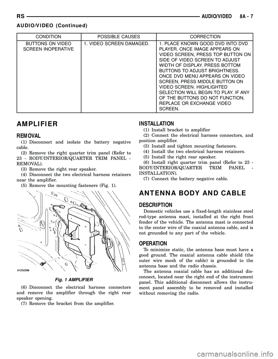
(5) Remove the mounting fasteners (Fig. 1).
(6) Disconnect the electrical harness connectors
and remove the amplifier through the right rear
speaker opening.
(7) Remove the bracket from the amplifier.
INSTALLATION
(1) Install bracket to amplifier
(2) Connect the electrical harness connectors, and
position amplifier.
(3) Install and tighten mounting fasteners.
(4) Install the two electrical harness retainers.
(5) Install the right rear speaker.
(6) Install right quarter trim panel (Refer to 23 -
BODY/INTERIOR/QUARTER TRIM PANEL -
INSTALLATION).
(7) Connect the battery negative cable.
ANTENNA BODY AND CABLE
DESCRIPTION
Domestic vehicles use a fixed-length stainless steel
rod-type antenna mast, installed at the right front
fender of the vehicle. The antenna mast is connected
to the center wire of the coaxial antenna cable, and is
not grounded to any part of the vehicle.
OPERATION
To minimize static, the antenna base must have a
good ground. The coaxial antenna cable shield (the
outer wire mesh of the cable) is grounded to the
antenna base and the radio chassis.
The antenna coaxial cable has an additional dis-
connect, located near the right end of the instrument
panel. This additional disconnect allows the instru-
ment panel assembly to be removed and installed
without removing the radio.
Fig. 1 AMPLIFIER
RSAUDIO/VIDEO8A-7
AUDIO/VIDEO (Continued)
Page 269 of 2339
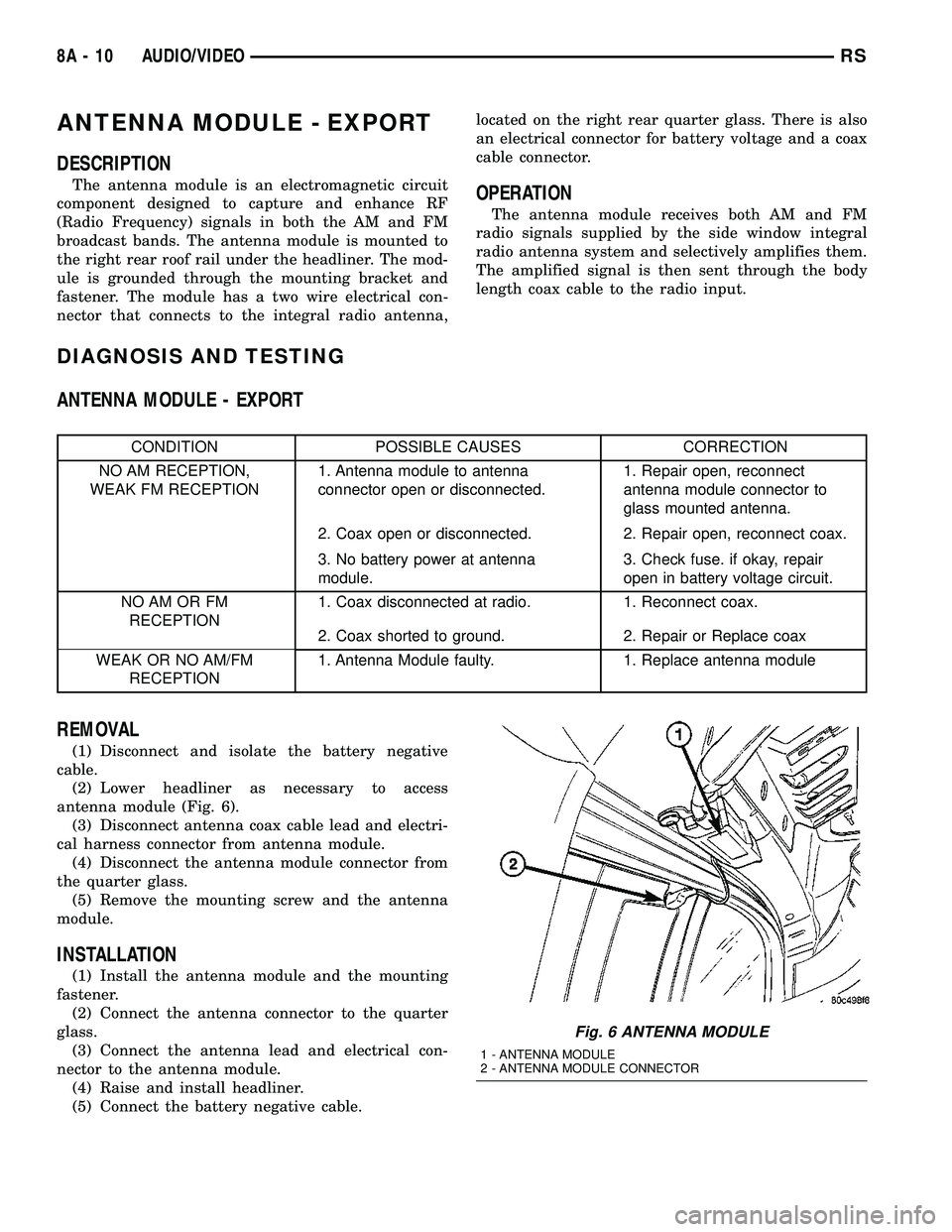
ANTENNA MODULE - EXPORT
DESCRIPTION
The antenna module is an electromagnetic circuit
component designed to capture and enhance RF
(Radio Frequency) signals in both the AM and FM
broadcast bands. The antenna module is mounted to
the right rear roof rail under the headliner. The mod-
ule is grounded through the mounting bracket and
fastener. The module has a two wire electrical con-
nector that connects to the integral radio antenna,located on the right rear quarter glass. There is also
an electrical connector for battery voltage and a coax
cable connector.OPERATION
The antenna module receives both AM and FM
radio signals supplied by the side window integral
radio antenna system and selectively amplifies them.
The amplified signal is then sent through the body
length coax cable to the radio input.
DIAGNOSIS AND TESTING
ANTENNA MODULE - EXPORT
CONDITION POSSIBLE CAUSES CORRECTION
NO AM RECEPTION,
WEAK FM RECEPTION1. Antenna module to antenna
connector open or disconnected.1. Repair open, reconnect
antenna module connector to
glass mounted antenna.
2. Coax open or disconnected. 2. Repair open, reconnect coax.
3. No battery power at antenna
module.3. Check fuse. if okay, repair
open in battery voltage circuit.
NO AM OR FM
RECEPTION1. Coax disconnected at radio. 1. Reconnect coax.
2. Coax shorted to ground. 2. Repair or Replace coax
WEAK OR NO AM/FM
RECEPTION1. Antenna Module faulty. 1. Replace antenna module
REMOVAL
(1) Disconnect and isolate the battery negative
cable.
(2) Lower headliner as necessary to access
antenna module (Fig. 6).
(3) Disconnect antenna coax cable lead and electri-
cal harness connector from antenna module.
(4) Disconnect the antenna module connector from
the quarter glass.
(5) Remove the mounting screw and the antenna
module.
INSTALLATION
(1) Install the antenna module and the mounting
fastener.
(2) Connect the antenna connector to the quarter
glass.
(3) Connect the antenna lead and electrical con-
nector to the antenna module.
(4) Raise and install headliner.
(5) Connect the battery negative cable.
Fig. 6 ANTENNA MODULE
1 - ANTENNA MODULE
2 - ANTENNA MODULE CONNECTOR
8A - 10 AUDIO/VIDEORS
Page 281 of 2339
PARK ASSIST SYSTEM
The Park Assist System display activates an audi-
ble tone that changes from intermittent to continu-
ous as the final two Light Emitting Diodes (LED's)
are illuminated on one side or both sides of the dis-
play.
The system detection length from the rear of the
vehicle is 0.3 meters to 1.5 meters. This area extends
around the rear side of the vehicle. The system detec-
tion height from the ground is 0.2 meters to about
1.5 meters. The radio mutes when the system acti-
vates its audible tone.
When the driver selects Reverse the system scans
for objects behind the vehicle using four sensors
located in the rear bumper. A warning display above
the rear window provides both visible and audible
warnings indicating the range of the object.
The system is active only when the transmission
gear selector is in reverse for vehicle speeds less than
16 Km/h (10 mph). If the vehicle's Parking/Emer-
gency Brake is applied, the system is deactivated.
The display contains two sets of yellow and red
Light Emitting Diode's (LED's) that the driver can
see as they look over their shoulder while backing
up. Each side of the vehicle has its own warning
LED's. The system provides a visual warning by illu-
minating one or more yellow LED's as the vehicle
gets closer to the object. As the vehicle continues to
approach the object, one red LED is illuminated and
the system emits a series of short beeps. The tone
will remain constant and both red LED's are illumi-
nated once the vehicle is within 12 inches (30.5 cm)
of the object.
The system can be turned ON or OFF through the
Electronic Vehicle Information Center (EVIC) when
the vehicle is in PARK. If the park assist system is
turned OFF, a single chime will sound and the EVIC
will display the following message ªREAR PARK
ASSIST OFFº, when the vehicle is in reverse.
²Ensure that the rear bumper is free of dirt and
debris to keep the system operating properly.
²Jackhammers, large trucks, and other vibrations
could affect the performance of the system.
²Ensure that the parking brake is not applied.
If ªService Park Assist Systemº appears in the
EVIC after making sure the rear bumper is clean,
proceed to diagnose the system using a scan tool and
the appropriate diagnostic information.
WARNING
On vehicles equipped with airbags, disable
the airbag system before attempting any steer-
ing wheel, steering column, or instrument
panel component diagnosis or service. Discon-
nect and isolate the battery negative (ground)
cable, then wait two minutes for the airbag sys-
tem capacitor to discharge before performing
further diagnosis or service. This is the only
sure way to disable the airbag system. Failure
to take the proper precautions could result in
accidental airbag deployment, personal injury,
or death.
DIAGNOSIS AND TESTING - CHIME SYSTEM
Refer to the proper Body Diagnostic Procedures
manual for complete Diagnosis and Testing of the
Chime System.
NO TONE WHEN IGNITION SWITCH IS TURNED ON
AND DRIVER'S SEAT BELT IS NOT BUCKLED.
(1) Using a DRB llltscan tool, actuate chime
(BCM actuates).
(2) Using a voltmeter, check for voltage:
(a) BCM has two battery feeds at pin 1 and pin
5 of the 6±way connector.
(b) Pin 5 of the (BX2) 32 way connector of the
BCM for ignition feed.
(c) Check voltage (PX2) connector, pin 34 for 12v.
(d) If voltage OK, go to step Step 3
(e) If NO voltage repair as necessary. Refer to
the appropriate wiring information. The wiring
information includes wiring diagrams, proper wire
and connector repair procedures, further details on
wire harness routing and retention, as well as pin-
out and location views for the various wire harness
connectors, splices and grounds.
(3) Check drivers seat belt buckle switch input
(from Occupant Restraint Controller (ORC) for a
closed circuit when not buckled. If input not seen,
look for open in wiring or switch. The switch is
grounded when belt is not buckled.
(4) Verify Programmable Communication Interface
(PCI) data bus communication between ORC and
BCM.
8B - 2 CHIME/BUZZERRS
CHIME/BUZZER (Continued)
Page 284 of 2339
²System diagnostics - diagnosis and error han-
dling (sensors, display, module).
²Data exchange over the Programmable Commu-
nication Interface (PCI) data bus.
OPERATION
The module has a number of functions:
²Supply voltage to the sensors and display.
²Disconnection of the display with bus idle and
over voltage Vmax.
²Triggering the sensors.
²Analyze echo delay times and calculate obstacle
distances.
²Bi-directional data communication to the display
for diagnosis.
²System diagnostics - diagnosis and error han-
dling (sensors, display, module).
²Data exchange over the Programmable Commu-
nication Interface (PCI) data bus.
The system detection length from the rear of the
vehicle is 0.3 meters to 1.5 meters. This area extends
around the rear side of the vehicle. The system detec-
tion height from the ground is 0.2 meters to about
1.5 meters. The radio mutes when the system acti-
vates its audible tone.When the driver selects Reverse, the system scans
for objects behind the vehicle using four sensors
located in the rear bumper. Objects can be detected
from up to 1.5 meters. A warning display above the
rear window provides both visible and audible warn-
ings indicating the range of the object.
The system is active only when the vehicle is in
reverse for vehicle speeds less than 16 Km/h (10
mph). If the vehicles Parking/Emergency Brake is
applied, the system is deactivated.
The display contains two sets of yellow and red
Light Emitting Diode's (LED's) that the driver can
see as they look over their shoulder while backing
up. Each side of the vehicle has its own warning
LED's. The system provides a visual warning by illu-
minating one or more yellow LED's as the vehicle
gets closer to the object. As the vehicle continues to
approaches the object, one red LED is illuminated
and the system emits a series of short beeps. The
tone will remain constant and both red LED's are
illuminated once the vehicle is within 12 inches (30.5
cm) of the object.
The system can be turned ON or OFF through the
Electronic Vehicle Information Center (EVIC) when
the vehicle is in PARK. If the park assist system is
turned OFF, a single chime will sound and the EVIC
will display the following message ªREAR PARK
ASSIST OFFº, when the vehicle is in reverse.
²Ensure that the rear bumper is free of dirt and
debris to keep the system operating properly.
²Jackhammers, large trucks, and other vibrations
could affect the performance of the system.
²Ensure that the parking brake is not applied.
If ªService Park Assist Systemº appears in the
EVIC after making sure the rear bumper is clean,
proceed to diagnose the system using a scan tool and
the appropriate diagnostic information.
To diagnose the Park Assist Module, use a scan
tool and the appropriate body diagnostic information.
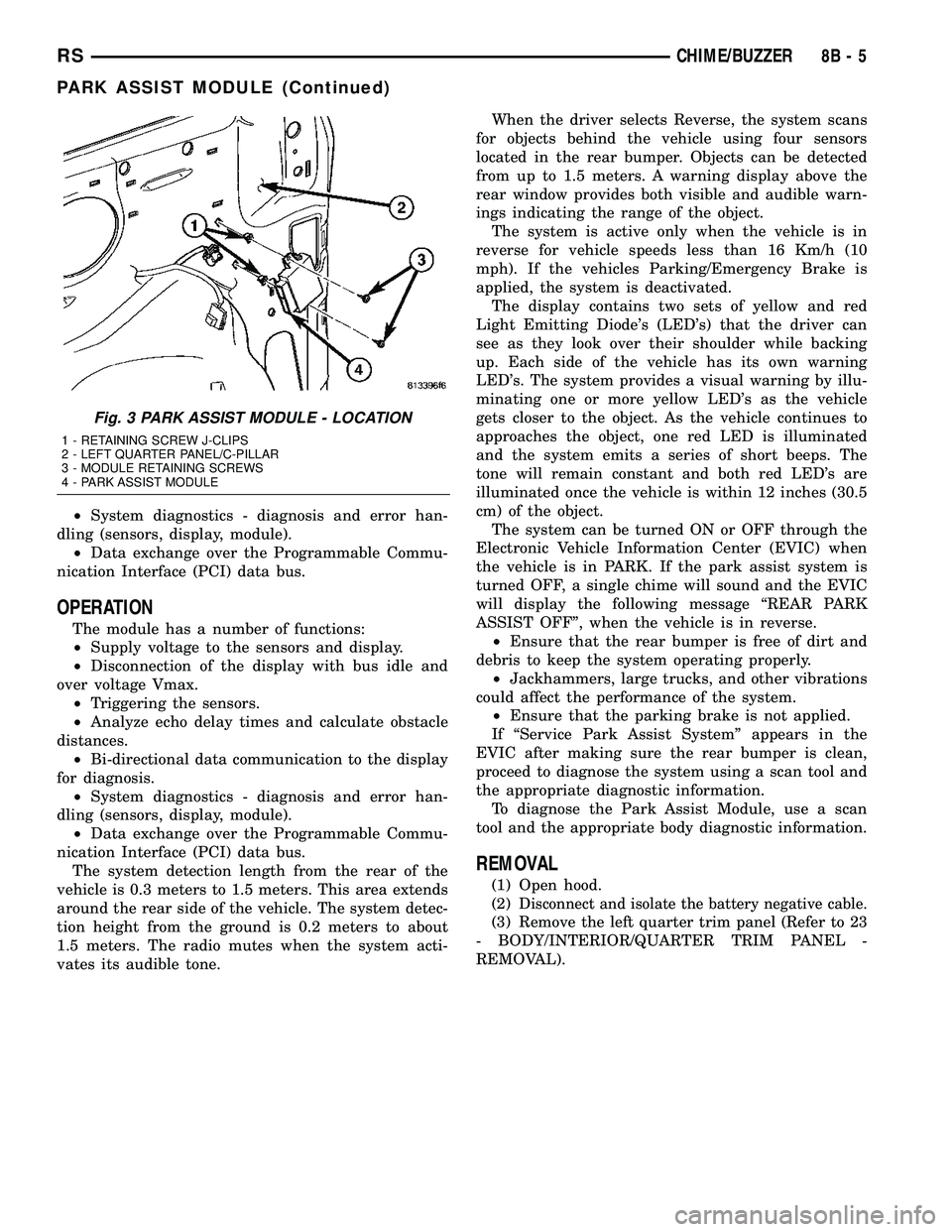
REMOVAL
(1) Open hood.
(2)
Disconnect and isolate the battery negative cable.
(3) Remove the left quarter trim panel (Refer to 23
- BODY/INTERIOR/QUARTER TRIM PANEL -
REMOVAL).
Fig. 3 PARK ASSIST MODULE - LOCATION
1 - RETAINING SCREW J-CLIPS
2 - LEFT QUARTER PANEL/C-PILLAR
3 - MODULE RETAINING SCREWS
4 - PARK ASSIST MODULE
RSCHIME/BUZZER8B-5
PARK ASSIST MODULE (Continued)
Page 285 of 2339
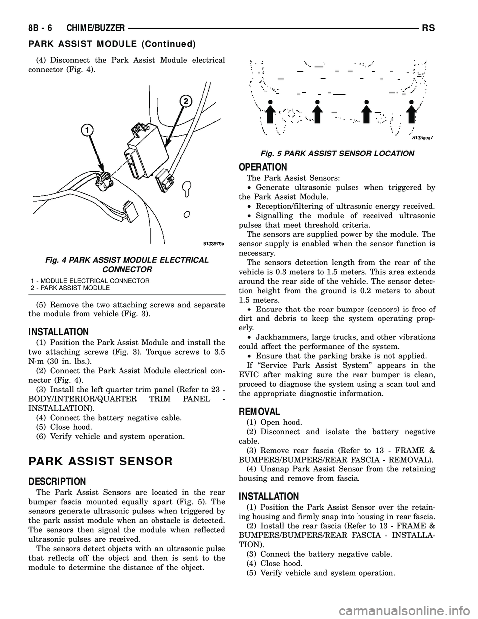
(4) Disconnect the Park Assist Module electrical
connector (Fig. 4).
(5) Remove the two attaching screws and separate
the module from vehicle (Fig. 3).
INSTALLATION
(1) Position the Park Assist Module and install the
two attaching screws (Fig. 3). Torque screws to 3.5
N´m (30 in. lbs.).
(2) Connect the Park Assist Module electrical con-
nector (Fig. 4).
(3) Install the left quarter trim panel (Refer to 23 -
BODY/INTERIOR/QUARTER TRIM PANEL -
INSTALLATION).
(4) Connect the battery negative cable.
(5) Close hood.
(6) Verify vehicle and system operation.
PARK ASSIST SENSOR
DESCRIPTION
The Park Assist Sensors are located in the rear
bumper fascia mounted equally apart (Fig. 5). The
sensors generate ultrasonic pulses when triggered by
the park assist module when an obstacle is detected.
The sensors then signal the module when reflected
ultrasonic pulses are received.
The sensors detect objects with an ultrasonic pulse
that reflects off the object and then is sent to the
module to determine the distance of the object.
OPERATION
The Park Assist Sensors:
²Generate ultrasonic pulses when triggered by
the Park Assist Module.
²Reception/filtering of ultrasonic energy received.
²Signalling the module of received ultrasonic
pulses that meet threshold criteria.
The sensors are supplied power by the module. The
sensor supply is enabled when the sensor function is
necessary.
The sensors detection length from the rear of the
vehicle is 0.3 meters to 1.5 meters. This area extends
around the rear side of the vehicle. The sensor detec-
tion height from the ground is 0.2 meters to about
1.5 meters.
²Ensure that the rear bumper (sensors) is free of
dirt and debris to keep the system operating prop-
erly.
²Jackhammers, large trucks, and other vibrations
could affect the performance of the system.
²Ensure that the parking brake is not applied.
If ªService Park Assist Systemº appears in the
EVIC after making sure the rear bumper is clean,
proceed to diagnose the system using a scan tool and
the appropriate diagnostic information.
REMOVAL
(1) Open hood.
(2) Disconnect and isolate the battery negative
cable.
(3) Remove rear fascia (Refer to 13 - FRAME &
BUMPERS/BUMPERS/REAR FASCIA - REMOVAL).
(4) Unsnap Park Assist Sensor from the retaining
housing and remove from fascia.
INSTALLATION
(1)Position the Park Assist Sensor over the retain-
ing housing and firmly snap into housing in rear fascia.
(2) Install the rear fascia (Refer to 13 - FRAME &
BUMPERS/BUMPERS/REAR FASCIA - INSTALLA-
TION).
(3) Connect the battery negative cable.
(4) Close hood.
(5) Verify vehicle and system operation.
Fig. 4 PARK ASSIST MODULE ELECTRICAL
CONNECTOR
1 - MODULE ELECTRICAL CONNECTOR
2 - PARK ASSIST MODULE
Fig. 5 PARK ASSIST SENSOR LOCATION
8B - 6 CHIME/BUZZERRS
PARK ASSIST MODULE (Continued)