Module CHRYSLER VOYAGER 2005 User Guide
[x] Cancel search | Manufacturer: CHRYSLER, Model Year: 2005, Model line: VOYAGER, Model: CHRYSLER VOYAGER 2005Pages: 2339, PDF Size: 59.69 MB
Page 162 of 2339
CAUTION: Do not reuse the original brake lamp
switch. The switch can only be adjusted once. That
is during initial installation of the switch. If the
switch is not adjusted properly or has been
removed for some service, a new switch must be
installed and adjusted.
(5) Remove and replace the brake lamp switch
with a NEW switch. (Refer to 8 - ELECTRICAL/
LAMPS/LIGHTING - EXTERIOR/BRAKE LAMP
SWITCH - REMOVAL), (Refer to 8 - ELECTRICAL/
LAMPS/LIGHTING - EXTERIOR/BRAKE LAMP
SWITCH - INSTALLATION)
(6) Install the silencer panel below the steering
column.
(7) Connect vacuum hose to check valve on power
brake booster.
CAUTION: The master cylinder (and its rear seal) is
used to create the seal for holding vacuum in the
vacuum booster. The vacuum seal on the master
cylinder MUST be replaced with a NEW seal when-
ever the master cylinder is removed from the vac-
uum booster.
CAUTION: When removing the vacuum seal from
the master cylinder do not use a sharp tool.
(8) Using a soft tool such as a trim stick, remove
the vacuum seal from the master cylinder mounting
flange.
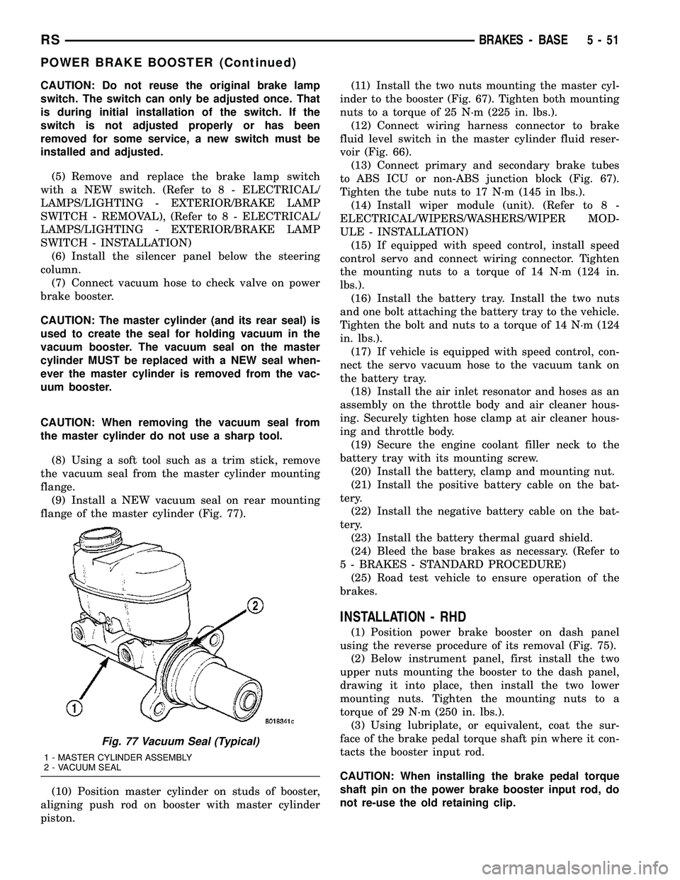
(9) Install a NEW vacuum seal on rear mounting
flange of the master cylinder (Fig. 77).
(10) Position master cylinder on studs of booster,
aligning push rod on booster with master cylinder
piston.(11) Install the two nuts mounting the master cyl-
inder to the booster (Fig. 67). Tighten both mounting
nuts to a torque of 25 N´m (225 in. lbs.).
(12) Connect wiring harness connector to brake
fluid level switch in the master cylinder fluid reser-
voir (Fig. 66).
(13) Connect primary and secondary brake tubes
to ABS ICU or non-ABS junction block (Fig. 67).
Tighten the tube nuts to 17 N´m (145 in lbs.).
(14) Install wiper module (unit). (Refer to 8 -
ELECTRICAL/WIPERS/WASHERS/WIPER MOD-
ULE - INSTALLATION)
(15) If equipped with speed control, install speed
control servo and connect wiring connector. Tighten
the mounting nuts to a torque of 14 N´m (124 in.
lbs.).
(16) Install the battery tray. Install the two nuts
and one bolt attaching the battery tray to the vehicle.
Tighten the bolt and nuts to a torque of 14 N´m (124
in. lbs.).
(17) If vehicle is equipped with speed control, con-
nect the servo vacuum hose to the vacuum tank on
the battery tray.
(18) Install the air inlet resonator and hoses as an
assembly on the throttle body and air cleaner hous-
ing. Securely tighten hose clamp at air cleaner hous-
ing and throttle body.
(19) Secure the engine coolant filler neck to the
battery tray with its mounting screw.
(20) Install the battery, clamp and mounting nut.
(21) Install the positive battery cable on the bat-
tery.
(22) Install the negative battery cable on the bat-
tery.
(23) Install the battery thermal guard shield.
(24) Bleed the base brakes as necessary. (Refer to
5 - BRAKES - STANDARD PROCEDURE)
(25) Road test vehicle to ensure operation of the
brakes.
INSTALLATION - RHD
(1) Position power brake booster on dash panel
using the reverse procedure of its removal (Fig. 75).
(2) Below instrument panel, first install the two
upper nuts mounting the booster to the dash panel,
drawing it into place, then install the two lower
mounting nuts. Tighten the mounting nuts to a
torque of 29 N´m (250 in. lbs.).
(3) Using lubriplate, or equivalent, coat the sur-
face of the brake pedal torque shaft pin where it con-
tacts the booster input rod.
CAUTION: When installing the brake pedal torque
shaft pin on the power brake booster input rod, do
not re-use the old retaining clip.
Fig. 77 Vacuum Seal (Typical)
1 - MASTER CYLINDER ASSEMBLY
2 - VACUUM SEAL
RSBRAKES - BASE5-51
POWER BRAKE BOOSTER (Continued)
Page 200 of 2339
START-UP CYCLE
When the ignition is turned on, a popping sound
and a slight brake pedal movement may be noticed.
The ABS warning lamp will also be on for up to 5
seconds after the ignition is turned on. When the
vehicle is first driven off, a humming may be heard
or felt by the driver at approximately 20±40 kph
(12±25 mph). All of these conditions are a normal
function of ABS as the system is performing a diag-
nosis check.
PREMATURE ABS CYCLING
Symptoms of premature ABS cycling include: click-
ing sounds from the solenoid valves; pump/motor
running; and pulsations in the brake pedal. Prema-
ture ABS cycling can occur at any braking rate of the
vehicle and on any type of road surface. Neither the
red BRAKE warning lamp, nor the amber ABS warn-
ing lamp, illuminate and no fault codes are stored in
the CAB.
Premature ABS cycling is a condition that needs to
be correctly assessed when diagnosing problems with
the antilock brake system. It may be necessary to use
a DRB scan tool to detect and verify premature ABS
cycling.
Check the following common causes when diagnos-
ing premature ABS cycling: damaged tone wheels;
incorrect tone wheels; damaged steering knuckle
wheel speed sensor mounting bosses; loose wheel
speed sensor mounting bolts; excessive tone wheel
runout; or an excessively large tone wheel-to-wheel
speed sensor air gap. Give special attention to these
components when diagnosing a vehicle exhibiting
premature ABS cycling.
After diagnosing the defective component, repair or
replace it as required. When the component repair or
replacement is completed, test drive the vehicle to
verify that premature ABS cycling has been cor-
rected.
OPERATION - ELECTRONIC VARIABLE BRAKE
PROPORTIONING
Upon entry into EVBP the inlet valve for the rear
brake circuit is switched on so that the fluid supply
from the master cylinder is shut off. In order to
decrease the rear brake pressure, the outlet valve for
the rear brake circuit is pulsed. This allows fluid to
enter the low pressure accumulator (LPA) in the
hydraulic control unit (HCU) resulting in a drop in
fluid pressure to the rear brakes. In order to increase
the rear brake pressure, the outlet valve is switched
off and the inlet valve is pulsed. This increases the
pressure to the rear brakes. This back-and-forth pro-
cess will continue until the required slip difference is
obtained. At the end of EVBP braking (brakes
released) the fluid in the LPA drains back to themaster cylinder by switching on the outlet valve and
draining through the inlet valve check valve. At the
same time the inlet valve is switched on in case of
another brake application.
The EVBP will remain functional during many
ABS fault modes. If both the red BRAKE and amber
ABS warning indicators are illuminated, the EVBP
may not be functioning.
OPERATION - TRACTION CONTROL SYSTEM
The traction control module monitors wheel speed.
During acceleration, if the module detects front
(drive) wheel slip and the brakes are not applied, the
module enters traction control mode. Traction control
operation proceeds in the following order:
(1) Close the normally open isolation valves.
(2) Start the pump/motor and supply volume and
pressure to the front (drive) hydraulic circuit. (The
pump/motor runs continuously during traction con-
trol operation.)
(3) Open and close the build and decay valves to
maintain minimum wheel slip and maximum trac-
tion.
The cycling of the build and decay valves during
traction control is similar to that during antilock
braking, except the valves work to control wheel spin
by applying the brakes, whereas the ABS function is
to control wheel skid by releasing the brakes.
If the brakes are applied at anytime during a trac-
tion control cycle, the brake lamp switch triggers the
controller to switch off traction control.
HYDRAULIC SHUTTLE VALVES
Two pressure relief hydraulic shuttle valves allow
pressure and volume to return to the master cylinder
reservoir when not consumed by the build and decay
valves. These valves are necessary because the
pump/motor supplies more volume than the system
requires.
TRACTION CONTROL LAMP
The traction control system is enabled at each igni-
tion cycle. It may be turned off by depressing the
Traction Control Off switch button when the ignition
is in the ON position. The traction control function
lamp (TRAC OFF) illuminates immediately upon
depressing the button.
The traction control function lamp illuminates dur-
ing a traction control cycle, displaying TRAC.
If the CAB calculates that the brake temperatures
are high, the traction control system becomes inoper-
ative until a time-out period has elapsed. During this
ªthermo-protection mode,º the traction control func-
tion lamp illuminates TRAC OFF; note that no trou-
ble code is registered.
RSBRAKES - ABS5-89
BRAKES - ABS (Continued)
Page 201 of 2339
CAUTION
The ABS uses an electronic control module, the
CAB. This module is designed to withstand normal
current draws associated with vehicle operation.
Care must be taken to avoid overloading the CAB
circuits.
CAUTION: In testing for open or short circuits, do
not ground or apply voltage to any of the circuits
unless instructed to do so for a diagnostic proce-
dure.
CAUTION: These circuits should only be tested
using a high impedance multi-meter or the DRBIIIT
scan tool as described in this section. Power
should never be removed or applied to any control
module with the ignition in the ON position. Before
removing or connecting battery cables, fuses, or
connectors, always turn the ignition to the OFF
position.
CAUTION: The CAB 24-way connector should never
be connected or disconnected with the ignition
switch in the ON position.
CAUTION: This vehicle utilizes active wheel speed
sensors. Do not apply voltage to wheel speed sen-
sors at any time.
CAUTION: Use only factory wiring harnesses. Do
not cut or splice wiring to the brake circuits. The
addition of aftermarket electrical equipment (car
phone, radar detector, citizen band radio, trailer
lighting, trailer brakes, etc.) on a vehicle equipped
with antilock brakes may affect the function of the
antilock brake system.
CAUTION: When performing any service procedure
on a vehicle equipped with ABS, do not apply a
12-volt power source to the ground circuit of the
pump motor in the HCU. Doing this will damage the
pump motor and will require replacement of the
entire HCU.
CAUTION: An attempt to remove or disconnect cer-
tain system components may result in improper
system operation. Only those components with
approved removal and installation procedures in
this manual should be serviced.
CAUTION: If welding work is to be performed on the
vehicle using an electric arc welder, the CAB con-nector should be disconnected during the welding
operation.
CAUTION: Many components of the ABS System
are not serviceable and must be replaced as an
assembly. Do not disassemble any component
which is not designed to be serviced.
CAUTION: Only the recommended jacking or hoist-
ing positions for this vehicle are to be used when-
ever it is necessary to lift a vehicle. Failure to raise
a vehicle from the recommended locations could
result in lifting a vehicle by the hydraulic control
unit mounting bracket. Lifting a vehicle by the
hydraulic control unit mounting bracket will result
in damage to the mounting bracket and the hydrau-
lic control unit.
CAUTION: Brake fluid will damage painted surfaces.
If brake fluid is spilled on any painted surface,
wash off with water immediately.
STANDARD PROCEDURE - ANTILOCK BRAKE
SYSTEM BLEEDING
The base brake's hydraulic system must be bled
anytime air enters the hydraulic system. The ABS
though, particularly the ICU (HCU), should only be
bled when the HCU is replaced or removed from the
vehicle. The ABS must always be bled anytime it is
suspected that the HCU has ingested air. Under
most circumstances that require the bleeding of the
brakes hydraulic system, only the base brake
hydraulic system needs to be bled.
It is important to note that excessive air in the
brake system will cause a soft or spongy feeling
brake pedal.
During the brake bleeding procedure, be sure the
brake fluid level remains close to the FULL level in
the master cylinder fluid reservoir. Check the fluid
level periodically during the bleeding procedure and
add DOT 3 brake fluid as required.
The ABS must be bled as two independent braking
systems. The non-ABS portion of the brake system
with ABS is to be bled the same as any non-ABS sys-
tem.
The ABS portion of the brake system must be bled
separately. Use the following procedure to properly
bleed the brake hydraulic system including the ABS.
BLEEDING
When bleeding the ABS system, the following
bleeding sequence must be followed to insure com-
plete and adequate bleeding.
5 - 90 BRAKES - ABSRS
BRAKES - ABS (Continued)
Page 213 of 2339
ICU (INTEGRATED CONTROL
UNIT)
DESCRIPTION
The hydraulic control unit (HCU) and the control-
ler antilock brake (CAB) used with this antilock
brake system are combined (integrated) into one
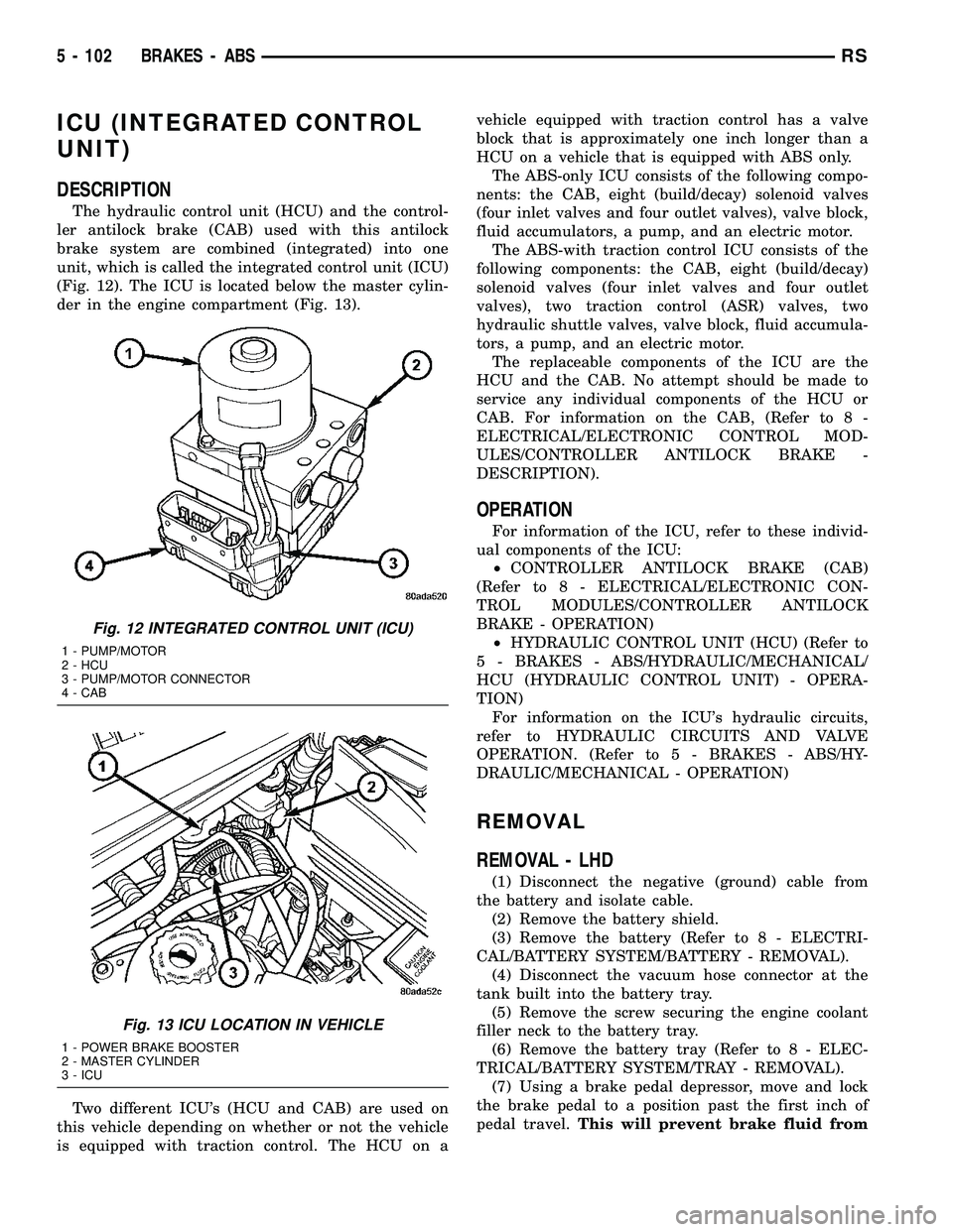
unit, which is called the integrated control unit (ICU)
(Fig. 12). The ICU is located below the master cylin-
der in the engine compartment (Fig. 13).
Two different ICU's (HCU and CAB) are used on
this vehicle depending on whether or not the vehicle
is equipped with traction control. The HCU on avehicle equipped with traction control has a valve
block that is approximately one inch longer than a
HCU on a vehicle that is equipped with ABS only.
The ABS-only ICU consists of the following compo-
nents: the CAB, eight (build/decay) solenoid valves
(four inlet valves and four outlet valves), valve block,
fluid accumulators, a pump, and an electric motor.
The ABS-with traction control ICU consists of the
following components: the CAB, eight (build/decay)
solenoid valves (four inlet valves and four outlet
valves), two traction control (ASR) valves, two
hydraulic shuttle valves, valve block, fluid accumula-
tors, a pump, and an electric motor.
The replaceable components of the ICU are the
HCU and the CAB. No attempt should be made to
service any individual components of the HCU or
CAB. For information on the CAB, (Refer to 8 -
ELECTRICAL/ELECTRONIC CONTROL MOD-
ULES/CONTROLLER ANTILOCK BRAKE -
DESCRIPTION).
OPERATION
For information of the ICU, refer to these individ-
ual components of the ICU:
²CONTROLLER ANTILOCK BRAKE (CAB)
(Refer to 8 - ELECTRICAL/ELECTRONIC CON-
TROL MODULES/CONTROLLER ANTILOCK
BRAKE - OPERATION)
²HYDRAULIC CONTROL UNIT (HCU) (Refer to
5 - BRAKES - ABS/HYDRAULIC/MECHANICAL/
HCU (HYDRAULIC CONTROL UNIT) - OPERA-
TION)
For information on the ICU's hydraulic circuits,
refer to HYDRAULIC CIRCUITS AND VALVE
OPERATION. (Refer to 5 - BRAKES - ABS/HY-
DRAULIC/MECHANICAL - OPERATION)
REMOVAL
REMOVAL - LHD
(1) Disconnect the negative (ground) cable from
the battery and isolate cable.
(2) Remove the battery shield.
(3) Remove the battery (Refer to 8 - ELECTRI-
CAL/BATTERY SYSTEM/BATTERY - REMOVAL).
(4) Disconnect the vacuum hose connector at the
tank built into the battery tray.
(5) Remove the screw securing the engine coolant
filler neck to the battery tray.
(6) Remove the battery tray (Refer to 8 - ELEC-
TRICAL/BATTERY SYSTEM/TRAY - REMOVAL).
(7) Using a brake pedal depressor, move and lock
the brake pedal to a position past the first inch of
pedal travel.This will prevent brake fluid from
Fig. 12 INTEGRATED CONTROL UNIT (ICU)
1 - PUMP/MOTOR
2 - HCU
3 - PUMP/MOTOR CONNECTOR
4 - CAB
Fig. 13 ICU LOCATION IN VEHICLE
1 - POWER BRAKE BOOSTER
2 - MASTER CYLINDER
3 - ICU
5 - 102 BRAKES - ABSRS
Page 225 of 2339

SPECIAL TOOLS
COOLING SYSTEM
Hose Clamp Pliers 6094
Hose Clamp Pliers 8495A
Cooling System Tester 7700
Coolant Refractometer 8286
Fig. 6 TOOL 8875A
DRB IIITwith PEP Module ± OT-CH6010A
Belt Tension Gauge Adapter 8371
Belt Tension Gauge 7198A
7 - 6 COOLINGRS
COOLING (Continued)
Page 242 of 2339
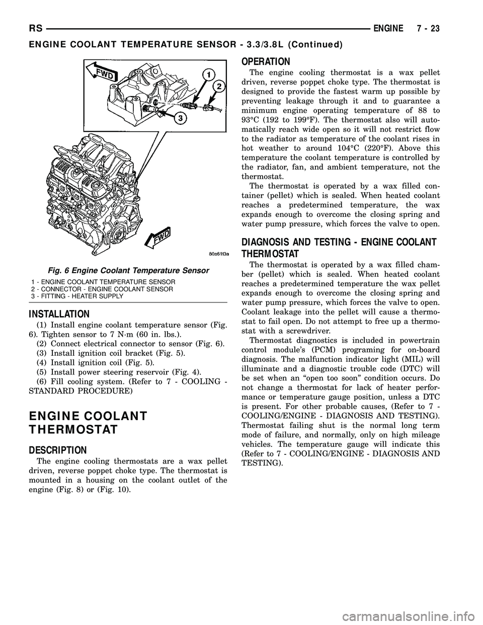
INSTALLATION
(1) Install engine coolant temperature sensor (Fig.
6). Tighten sensor to 7 N´m (60 in. lbs.).
(2) Connect electrical connector to sensor (Fig. 6).
(3) Install ignition coil bracket (Fig. 5).
(4) Install ignition coil (Fig. 5).
(5) Install power steering reservoir (Fig. 4).
(6) Fill cooling system. (Refer to 7 - COOLING -
STANDARD PROCEDURE)
ENGINE COOLANT
THERMOSTAT
DESCRIPTION
The engine cooling thermostats are a wax pellet
driven, reverse poppet choke type. The thermostat is
mounted in a housing on the coolant outlet of the
engine (Fig. 8) or (Fig. 10).
OPERATION
The engine cooling thermostat is a wax pellet
driven, reverse poppet choke type. The thermostat is
designed to provide the fastest warm up possible by
preventing leakage through it and to guarantee a
minimum engine operating temperature of 88 to
93ÉC (192 to 199ÉF). The thermostat also will auto-
matically reach wide open so it will not restrict flow
to the radiator as temperature of the coolant rises in
hot weather to around 104ÉC (220ÉF). Above this
temperature the coolant temperature is controlled by
the radiator, fan, and ambient temperature, not the
thermostat.
The thermostat is operated by a wax filled con-
tainer (pellet) which is sealed. When heated coolant
reaches a predetermined temperature, the wax
expands enough to overcome the closing spring and
water pump pressure, which forces the valve to open.
DIAGNOSIS AND TESTING - ENGINE COOLANT
THERMOSTAT
The thermostat is operated by a wax filled cham-
ber (pellet) which is sealed. When heated coolant
reaches a predetermined temperature the wax pellet
expands enough to overcome the closing spring and
water pump pressure, which forces the valve to open.
Coolant leakage into the pellet will cause a thermo-
stat to fail open. Do not attempt to free up a thermo-
stat with a screwdriver.
Thermostat diagnostics is included in powertrain
control module's (PCM) programing for on-board
diagnosis. The malfunction indicator light (MIL) will
illuminate and a diagnostic trouble code (DTC) will
be set when an ªopen too soonº condition occurs. Do
not change a thermostat for lack of heater perfor-
mance or temperature gauge position, unless a DTC
is present. For other probable causes, (Refer to 7 -
COOLING/ENGINE - DIAGNOSIS AND TESTING).
Thermostat failing shut is the normal long term
mode of failure, and normally, only on high mileage
vehicles. The temperature gauge will indicate this
(Refer to 7 - COOLING/ENGINE - DIAGNOSIS AND
TESTING).Fig. 6 Engine Coolant Temperature Sensor
1 - ENGINE COOLANT TEMPERATURE SENSOR
2 - CONNECTOR - ENGINE COOLANT SENSOR
3 - FITTING - HEATER SUPPLY
RSENGINE7-23
ENGINE COOLANT TEMPERATURE SENSOR - 3.3/3.8L (Continued)
Page 249 of 2339

DIAGNOSIS AND TESTING - RADIATOR FAN MOTOR
RADIATOR FAN DIAGNOSIS CHART
CONDITION POSSIBLE CAUSES CORRECTION
NOISY RADIATOR FAN 1. Fan blade loose. 1. Replace fan assembly. (Refer to
7 - COOLING/ENGINE/RADIATOR
FAN - REMOVAL)
2. Fan blade striking a surrounding
object.2. Locate point of fan blade contact
and repair as necessary.
3. Air obstructions at radiator or A/C
condenser.3. Remove obstructions and/or
clean debris.
4. Electric fan motor defective. 4. Replace fan assembly. (Refer to
7 - COOLING/ENGINE/RADIATOR
FAN - REMOVAL)
ELECTRIC FAN MOTOR DOES
NOT OPERATE1. Fan relay, powertrain control
module (PCM), coolant temperature
sensor, or wiring defective.1. (Refer to Appropriate Diagnostic
Information) Repair as necessary.
2. Defective A/C pressure
transducer.2. (Refer to Appropriate Diagnostic
Information) Repair as necessary.
ELECTRIC RADIATOR FAN
OPERATES ALL THE TIME1. Fan relay, powertrain control
module (PCM), coolant temperature
sensor or wiring defective.1. (Refer to Appropriate Diagnostic
Information) Repair as necessary.
2. Check for low coolant level. 2. Add coolant as necessary.
3. Defective A/C pressure
transducer.3. (Refer to Appropriate Diagnostic
Information) Repair as necessary.
REMOVAL
There are no repairs to be made to the fan or
shroud assembly. If the fan is warped, cracked, or
otherwise damaged, it must be replaced as an assem-
bly (Fig. 20).
(1) Remove the radiator upper crossmember. (Refer
to 23 - BODY/EXTERIOR/GRILLE OPENING REIN-
FORCEMENT - REMOVAL)
(2) Disconnect the radiator fan electrical connec-
tors.
(3) Remove radiator fan(s) retaining screw (Fig.
20).
(4) Remove the radiator fan(s) by lifting upward to
release from mounts.
INSTALLATION
(1) Install the radiator fan(s) into mounts and
attaching clips on the radiator.
(2) Install radiator fan(s) attaching screws (Fig.
20). Tighten to 5 N´m (45 in. lbs.).
(3) Connect the radiator fan(s) electrical connec-
tors.(4) Install the radiator upper support crossmem-
ber. (Refer to 23 - BODY/EXTERIOR/GRILLE OPEN-
ING REINFORCEMENT - INSTALLATION)
Fig. 20 Radiator Fans
1 - SCREWS - RADIATOR FAN ATTACHING
2 - RADIATOR FAN - RIGHT
3 - MOUNT - RIGHT RADIATOR FAN
4 - CLIPS - RADIATOR FAN LOWER
5 - MOUNT - LEFT RADIATOR FAN
6 - RADIATOR FAN - LEFT
7 - 30 ENGINERS
RADIATOR FAN (Continued)
Page 250 of 2339
(5) Install the upper radiator mounts to the cross-
member bolts, if removed. Tighten to 8 N´m (70 in.
lbs.).
(6) Install the radiator upper hose to the support
clip (2.4L engine).
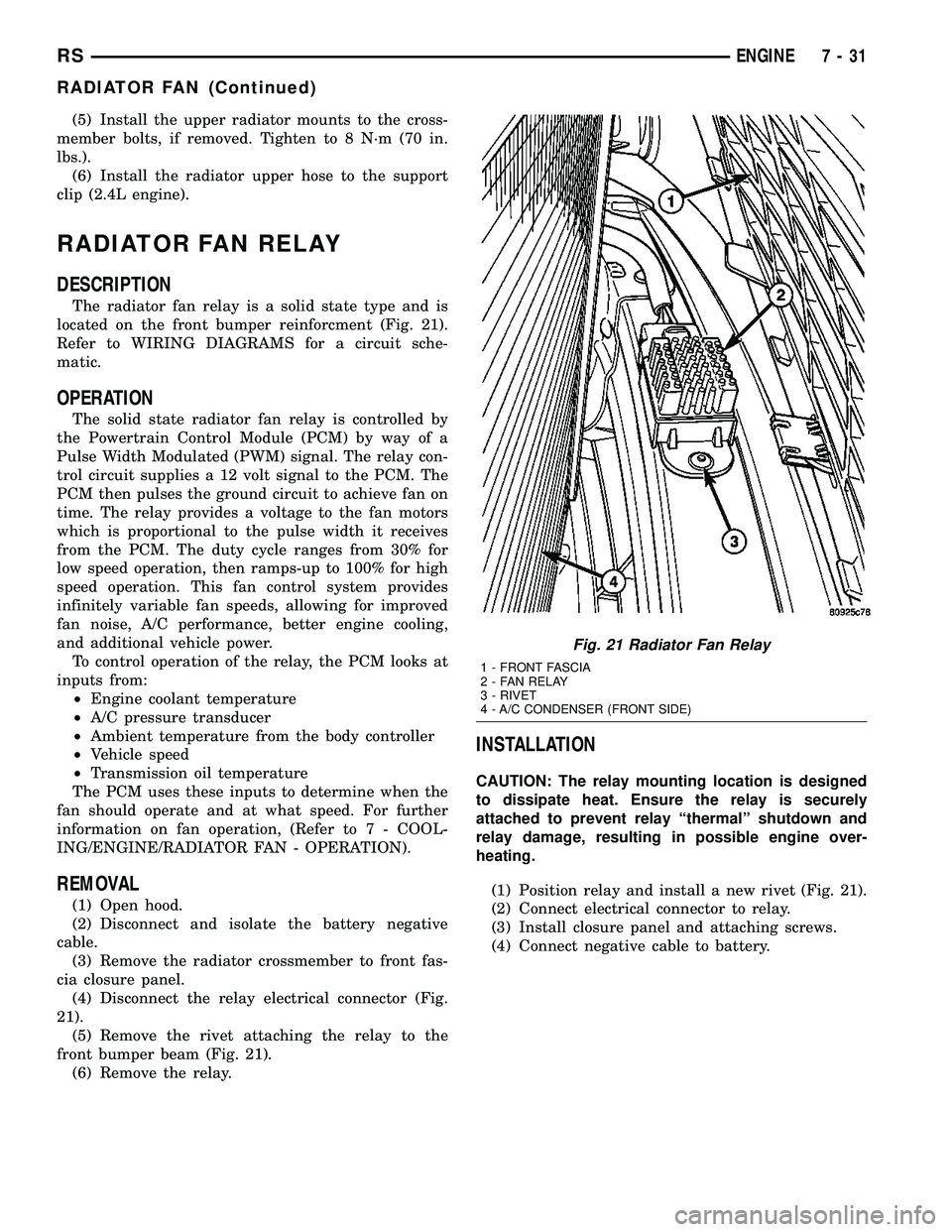
RADIATOR FAN RELAY
DESCRIPTION
The radiator fan relay is a solid state type and is
located on the front bumper reinforcment (Fig. 21).
Refer to WIRING DIAGRAMS for a circuit sche-
matic.
OPERATION
The solid state radiator fan relay is controlled by
the Powertrain Control Module (PCM) by way of a
Pulse Width Modulated (PWM) signal. The relay con-
trol circuit supplies a 12 volt signal to the PCM. The
PCM then pulses the ground circuit to achieve fan on
time. The relay provides a voltage to the fan motors
which is proportional to the pulse width it receives
from the PCM. The duty cycle ranges from 30% for
low speed operation, then ramps-up to 100% for high
speed operation. This fan control system provides
infinitely variable fan speeds, allowing for improved
fan noise, A/C performance, better engine cooling,
and additional vehicle power.
To control operation of the relay, the PCM looks at
inputs from:
²Engine coolant temperature
²A/C pressure transducer
²Ambient temperature from the body controller
²Vehicle speed
²Transmission oil temperature
The PCM uses these inputs to determine when the
fan should operate and at what speed. For further
information on fan operation, (Refer to 7 - COOL-
ING/ENGINE/RADIATOR FAN - OPERATION).
REMOVAL
(1) Open hood.
(2) Disconnect and isolate the battery negative
cable.
(3) Remove the radiator crossmember to front fas-
cia closure panel.
(4) Disconnect the relay electrical connector (Fig.
21).
(5) Remove the rivet attaching the relay to the
front bumper beam (Fig. 21).
(6) Remove the relay.
INSTALLATION
CAUTION: The relay mounting location is designed
to dissipate heat. Ensure the relay is securely
attached to prevent relay ªthermalº shutdown and
relay damage, resulting in possible engine over-
heating.
(1) Position relay and install a new rivet (Fig. 21).
(2) Connect electrical connector to relay.
(3) Install closure panel and attaching screws.
(4) Connect negative cable to battery.
Fig. 21 Radiator Fan Relay
1 - FRONT FASCIA
2 - FAN RELAY
3 - RIVET
4 - A/C CONDENSER (FRONT SIDE)
RSENGINE7-31
RADIATOR FAN (Continued)
Page 260 of 2339
AUDIO/VIDEO
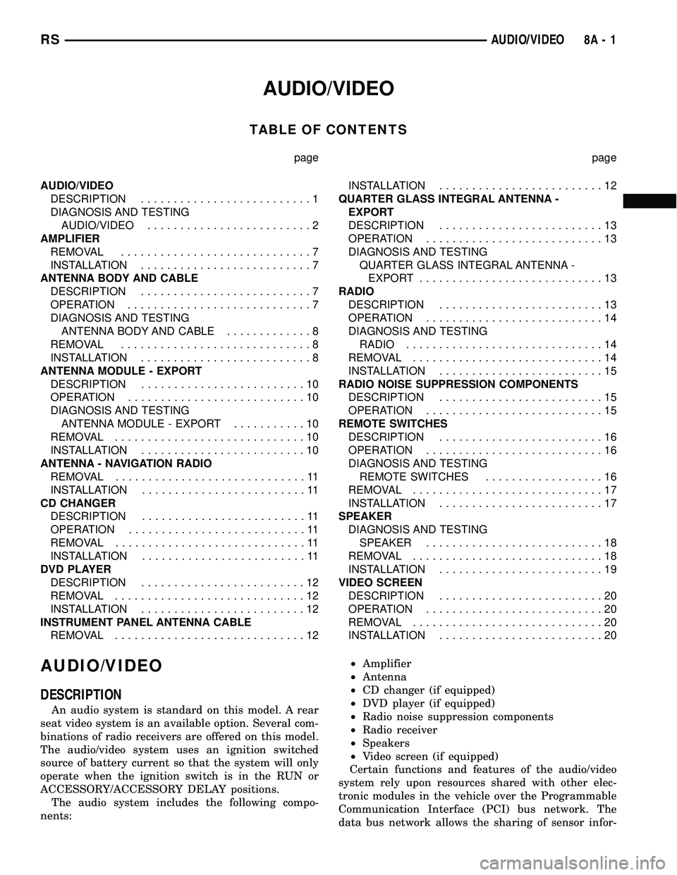
TABLE OF CONTENTS
page page
AUDIO/VIDEO
DESCRIPTION..........................1
DIAGNOSIS AND TESTING
AUDIO/VIDEO.........................2
AMPLIFIER
REMOVAL.............................7
INSTALLATION..........................7
ANTENNA BODY AND CABLE
DESCRIPTION..........................7
OPERATION............................7
DIAGNOSIS AND TESTING
ANTENNA BODY AND CABLE.............8
REMOVAL.............................8
INSTALLATION..........................8
ANTENNA MODULE - EXPORT
DESCRIPTION.........................10
OPERATION...........................10
DIAGNOSIS AND TESTING
ANTENNA MODULE - EXPORT...........10
REMOVAL.............................10
INSTALLATION.........................10
ANTENNA - NAVIGATION RADIO
REMOVAL.............................11
INSTALLATION.........................11
CD CHANGER
DESCRIPTION.........................11
OPERATION...........................11
REMOVAL.............................11
INSTALLATION.........................11
DVD PLAYER
DESCRIPTION.........................12
REMOVAL.............................12
INSTALLATION.........................12
INSTRUMENT PANEL ANTENNA CABLE
REMOVAL.............................12INSTALLATION.........................12
QUARTER GLASS INTEGRAL ANTENNA -
EXPORT
DESCRIPTION.........................13
OPERATION...........................13
DIAGNOSIS AND TESTING
QUARTER GLASS INTEGRAL ANTENNA -
EXPORT............................13
RADIO
DESCRIPTION.........................13
OPERATION...........................14
DIAGNOSIS AND TESTING
RADIO..............................14
REMOVAL.............................14
INSTALLATION.........................15
RADIO NOISE SUPPRESSION COMPONENTS
DESCRIPTION.........................15
OPERATION...........................15
REMOTE SWITCHES
DESCRIPTION.........................16
OPERATION...........................16
DIAGNOSIS AND TESTING
REMOTE SWITCHES..................16
REMOVAL.............................17
INSTALLATION.........................17
SPEAKER
DIAGNOSIS AND TESTING
SPEAKER...........................18
REMOVAL.............................18
INSTALLATION.........................19
VIDEO SCREEN
DESCRIPTION.........................20
OPERATION...........................20
REMOVAL.............................20
INSTALLATION.........................20
AUDIO/VIDEO
DESCRIPTION
An audio system is standard on this model. A rear
seat video system is an available option. Several com-
binations of radio receivers are offered on this model.
The audio/video system uses an ignition switched
source of battery current so that the system will only
operate when the ignition switch is in the RUN or
ACCESSORY/ACCESSORY DELAY positions.
The audio system includes the following compo-
nents:²Amplifier
²Antenna
²CD changer (if equipped)
²DVD player (if equipped)
²Radio noise suppression components
²Radio receiver
²Speakers
²Video screen (if equipped)
Certain functions and features of the audio/video
system rely upon resources shared with other elec-
tronic modules in the vehicle over the Programmable
Communication Interface (PCI) bus network. The
data bus network allows the sharing of sensor infor-
RSAUDIO/VIDEO8A-1
Page 261 of 2339
mation. For diagnosis of these electronic modules or
of the data bus network, the use of a DRB IIItscan
tool and the proper Diagnostic Procedures informa-
tion is recommended.
DIAGNOSIS AND TESTING
AUDIO/VIDEO
Any diagnosis of the Audio system should
begin with the use of the DRB IIItdiagnostic
tool. For information on the use of the DRBIIIt, refer to the appropriate Diagnostic Service
information.
Refer to the appropriate wiring information.
WARNING: ON VEHICLES EQUIPPED WITH AIR-
BAGS, REFER TO ELECTRICAL, RESTRAINTS
BEFORE ATTEMPTING ANY STEERING WHEEL,
STEERING COLUMN, OR INSTRUMENT PANEL
COMPONENT DIAGNOSIS OR SERVICE. FAILURE
TO TAKE THE PROPER PRECAUTIONS COULD
RESULT IN ACCIDENTAL AIRBAG DEPLOYMENT
AND POSSIBLE PERSONAL INJURY.
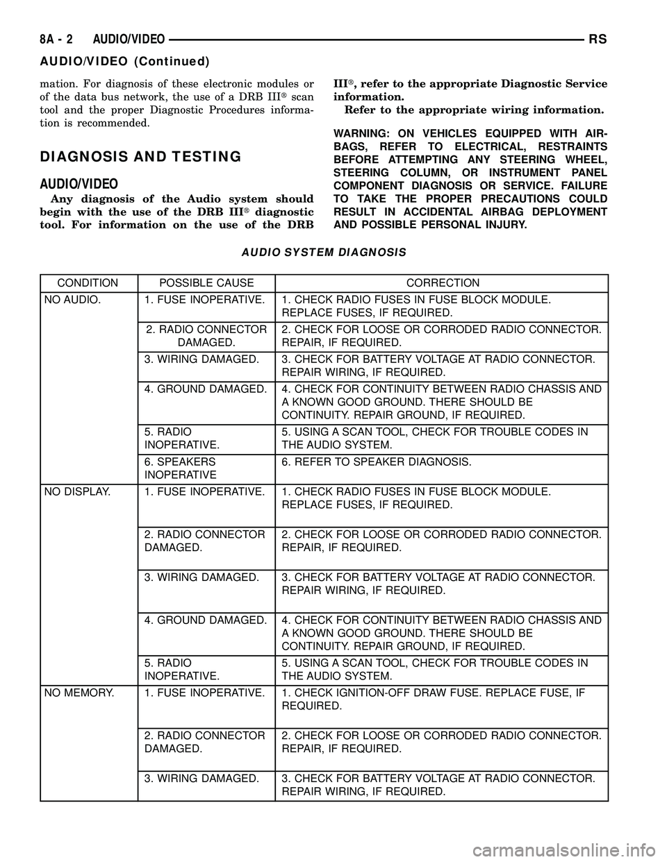
AUDIO SYSTEM DIAGNOSIS
CONDITION POSSIBLE CAUSE CORRECTION
NO AUDIO. 1. FUSE INOPERATIVE. 1. CHECK RADIO FUSES IN FUSE BLOCK MODULE.
REPLACE FUSES, IF REQUIRED.
2. RADIO CONNECTOR
DAMAGED.2. CHECK FOR LOOSE OR CORRODED RADIO CONNECTOR.
REPAIR, IF REQUIRED.
3. WIRING DAMAGED. 3. CHECK FOR BATTERY VOLTAGE AT RADIO CONNECTOR.
REPAIR WIRING, IF REQUIRED.
4. GROUND DAMAGED. 4. CHECK FOR CONTINUITY BETWEEN RADIO CHASSIS AND
A KNOWN GOOD GROUND. THERE SHOULD BE
CONTINUITY. REPAIR GROUND, IF REQUIRED.
5. RADIO
INOPERATIVE.5. USING A SCAN TOOL, CHECK FOR TROUBLE CODES IN
THE AUDIO SYSTEM.
6. SPEAKERS
INOPERATIVE6. REFER TO SPEAKER DIAGNOSIS.
NO DISPLAY. 1. FUSE INOPERATIVE. 1. CHECK RADIO FUSES IN FUSE BLOCK MODULE.
REPLACE FUSES, IF REQUIRED.
2. RADIO CONNECTOR
DAMAGED.2. CHECK FOR LOOSE OR CORRODED RADIO CONNECTOR.
REPAIR, IF REQUIRED.
3. WIRING DAMAGED. 3. CHECK FOR BATTERY VOLTAGE AT RADIO CONNECTOR.
REPAIR WIRING, IF REQUIRED.
4. GROUND DAMAGED. 4. CHECK FOR CONTINUITY BETWEEN RADIO CHASSIS AND
A KNOWN GOOD GROUND. THERE SHOULD BE
CONTINUITY. REPAIR GROUND, IF REQUIRED.
5. RADIO
INOPERATIVE.5. USING A SCAN TOOL, CHECK FOR TROUBLE CODES IN
THE AUDIO SYSTEM.
NO MEMORY. 1. FUSE INOPERATIVE. 1. CHECK IGNITION-OFF DRAW FUSE. REPLACE FUSE, IF
REQUIRED.
2. RADIO CONNECTOR
DAMAGED.2. CHECK FOR LOOSE OR CORRODED RADIO CONNECTOR.
REPAIR, IF REQUIRED.
3. WIRING DAMAGED. 3. CHECK FOR BATTERY VOLTAGE AT RADIO CONNECTOR.
REPAIR WIRING, IF REQUIRED.
8A - 2 AUDIO/VIDEORS
AUDIO/VIDEO (Continued)