buttons CHRYSLER VOYAGER 2005 Service Manual
[x] Cancel search | Manufacturer: CHRYSLER, Model Year: 2005, Model line: VOYAGER, Model: CHRYSLER VOYAGER 2005Pages: 2339, PDF Size: 59.69 MB
Page 265 of 2339
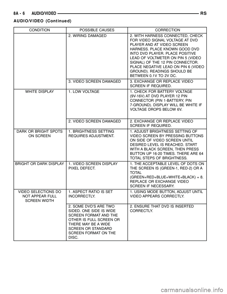
CONDITION POSSIBLE CAUSES CORRECTION
2. WIRING DAMAGED 2. WITH HARNESS CONNECTED, CHECK
FOR VIDEO SIGNAL VOLTAGE AT DVD
PLAYER AND AT VIDEO SCREEN
HARNESS. PLACE KNOWN GOOD DVD
INTO DVD PLAYER. PLACE POSITIVE
LEAD OF VOLTMETER ON PIN 5 (VIDEO
SIGNAL) OF THE 12 PIN CONNECTOR.
PLACE NEGATIVE LEAD ON PIN 6 (VIDEO
GROUND). READINGS SHOULD BE
BETWEEN 0.1V TO 2V DC.
3. VIDEO SCREEN DAMAGED 3. EXCHANGE OR REPLACE VIDEO
SCREEN IF REQUIRED.
WHITE DISPLAY 1. LOW VOLTAGE 1. CHECK FOR BATTERY VOLTAGE
(9V-16V) AT DVD PLAYER 12 PIN
CONNECTOR (PIN 1-BATTERY, PIN
7-GROUND). DISPLAY WILL BE WHITE IF
VOLTAGE DROPS BELOW 6V.
2. VIDEO SCREEN DAMAGED 2. EXCHANGE OR REPLACE VIDEO
SCREEN IF REQUIRED.
DARK OR BRIGHT SPOTS
ON SCREEN1. BRIGHTNESS SETTING
REQUIRES ADJUSTMENT.1. ADJUST BRIGHTNESS SETTING OF
VIDEO SCREEN BY PRESSING BUTTONS
ON SIDE OF VIDEO SCREEN UNTIL
DESIRED LEVEL IS REACHED. START
WITH A BLACK SCREEN, THEN PRESS
BUTTON UP 16-20 TIMES. THERE ARE 64
TOTAL STEPS OF BRIGHTNESS.
BRIGHT OR DARK DISPLAY 1. VIDEO SCREEN DISPLAY
PIXEL DEFECT.1. THE ACCEPTABLE LEVEL OF DOTS ON
THE SCREEN IS (GREEN-1, RED-2) OR A
TOTAL
(GREEN+RED+BLUE+WHITE+BLACK) = 8.
REPLACE OR EXCHANGE VIDEO
SCREEN IF NECESSARY.
VIDEO SELECTIONS DO
NOT APPEAR FULL
SCREEN WIDTH1. ASPECT RATIO IS SET
INCORRECTLY.1. USING MODE BUTTON, ADJUST UNTIL
VIDEO APPEARS CORRECTLY.
2. SOME DVD'S ARE TWO
SIDED. ONE SIDE IS WIDE
SCREEN FORMAT AND THE
OTHER IS FULL SCREEN OR
THERE MAY BE A WIDE
SCREEN OR STANDARD
SCREEN FORMAT ON THE
DISC.2. ENSURE THAT DVD IS INSERTED
CORRECTLY.
8A - 6 AUDIO/VIDEORS
AUDIO/VIDEO (Continued)
Page 266 of 2339
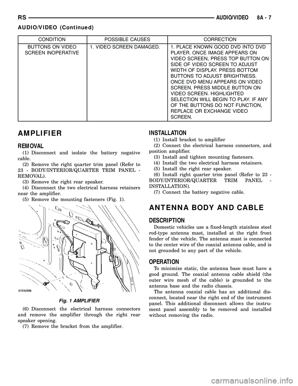
CONDITION POSSIBLE CAUSES CORRECTION
BUTTONS ON VIDEO
SCREEN INOPERATIVE1. VIDEO SCREEN DAMAGED. 1. PLACE KNOWN GOOD DVD INTO DVD
PLAYER. ONCE IMAGE APPEARS ON
VIDEO SCREEN, PRESS TOP BUTTON ON
SIDE OF VIDEO SCREEN TO ADJUST
WIDTH OF DISPLAY. PRESS BOTTOM
BUTTONS TO ADJUST BRIGHTNESS.
ONCE DVD MENU APPEARS ON VIDEO
SCREEN, PRESS MIDDLE BUTTON ON
VIDEO SCREEN. HIGHLIGHTED
SELECTION WILL BEGIN TO PLAY. IF ANY
OF THE BUTTONS DO NOT FUNCTION,
REPLACE OR EXCHANGE VIDEO
SCREEN.
AMPLIFIER
REMOVAL
(1) Disconnect and isolate the battery negative
cable.
(2) Remove the right quarter trim panel (Refer to
23 - BODY/INTERIOR/QUARTER TRIM PANEL -
REMOVAL).
(3) Remove the right rear speaker.
(4) Disconnect the two electrical harness retainers
near the amplifier.
(5) Remove the mounting fasteners (Fig. 1).
(6) Disconnect the electrical harness connectors
and remove the amplifier through the right rear
speaker opening.
(7) Remove the bracket from the amplifier.
INSTALLATION
(1) Install bracket to amplifier
(2) Connect the electrical harness connectors, and
position amplifier.
(3) Install and tighten mounting fasteners.
(4) Install the two electrical harness retainers.
(5) Install the right rear speaker.
(6) Install right quarter trim panel (Refer to 23 -
BODY/INTERIOR/QUARTER TRIM PANEL -
INSTALLATION).
(7) Connect the battery negative cable.
ANTENNA BODY AND CABLE
DESCRIPTION
Domestic vehicles use a fixed-length stainless steel
rod-type antenna mast, installed at the right front
fender of the vehicle. The antenna mast is connected
to the center wire of the coaxial antenna cable, and is
not grounded to any part of the vehicle.
OPERATION
To minimize static, the antenna base must have a
good ground. The coaxial antenna cable shield (the
outer wire mesh of the cable) is grounded to the
antenna base and the radio chassis.
The antenna coaxial cable has an additional dis-
connect, located near the right end of the instrument
panel. This additional disconnect allows the instru-
ment panel assembly to be removed and installed
without removing the radio.
Fig. 1 AMPLIFIER
RSAUDIO/VIDEO8A-7
AUDIO/VIDEO (Continued)
Page 270 of 2339

ANTENNA - NAVIGATION
RADIO
REMOVAL
(1) Disconnect and isolate the battery negative
cable.
(2) Remove the radio (Refer to 8 - ELECTRICAL/
AUDIO/RADIO - REMOVAL).
(3) Disconnect antenna from radio (Fig. 7). Remove
tape securing antenna to air duct, and remove
antenna (Fig. 8).
INSTALLATION
(1) Secure antenna to air duct.
(2) Connect antenna to radio.
(3) Install radio (Refer to 8 - ELECTRICAL/AU-
DIO/RADIO - INSTALLATION).
(4) Connect battery negative cable.
CD CHANGER
DESCRIPTION
The 6 Disc In-Dash CD Changer (if equipped) is
located in the instrument panel below the radio. The
remote changer does not use a cartridge or magazine
for the CD's. Up to 6 CD's can be directly loaded into
this unit.
OPERATION
Due to its compact design, the CD changer can
carry out only one operation at a time. For example,
you can not load a new disc while playing another at
the same time. Each operation happens sequentially.
The radio unit provides control over all features of
the CD changer with the exception of the CD load
and eject functions, which are controlled by buttons
located on the front of the CD changer. All features
you would expect, such as Disc Up/Down, Track
Up/Down, Random and Scan are controlled by the
radio, which also displays all relevant CD changer
information on the radio display.
The CD changer contains a Eject button, six disc
buttons, an indicator LED for each of the six disc
positions as well as an illuminated disc opening. The
individual LED indicates whether a CD is currently
loaded in that particular chamber of the CD changer.
Pressing the individual button for a particular cham-
ber, then the Eject button will eject a disc currently
present in that chamber. If the chamber is currently
empty, actuating the individual button will position
that chamber to receive and load a new disc in that
chamber.
REMOVAL
(1) Disconnect and isolate the battery negative
cable.
(2) Remove screws holding CD changer.
(3) Disconnect the wire connector from the back of
the CD changer.
(4) Remove the CD changer from the vehicle (Fig.
9).
INSTALLATION
(1) Reconnect the wire connector to the CD
changer.
(2) Insert the CD changer into the instrument
panel.
NOTE: Use care when inserting CD changer so that
cable is not pinched or trapped against instrument
panel.
Fig. 7 NAVIGATION ANTENNA
Fig. 8 NAVIGATION ANTENNA MOUNTING
RSAUDIO/VIDEO8A-11
Page 273 of 2339
OPERATION
The radio receiver operates on ignition switched
battery current that is available only when the igni-
tion switch is in the On or Accessory/Accessory Delay
positions. The electronic digital clock function of the
radio operates on fused battery current supplied
through the IOD fuse, regardless of the ignition
switch position.
For complete circuit diagrams, refer to the appro-
priate wiring information.
DIAGNOSIS AND TESTING
RADIO
WARNING: ON VEHICLES EQUIPPED WITH AIR-
BAGS, REFER TO ELECTRICAL, RESTRAINTS
BEFORE ATTEMPTING ANY STEERING WHEEL,
STEERING COLUMN, OR INSTRUMENT PANEL
COMPONENT DIAGNOSIS OR SERVICE. FAILURE
TO TAKE THE PROPER PRECAUTIONS COULD
RESULT IN ACCIDENTAL AIRBAG DEPLOYMENT
AND POSSIBLE PERSONAL INJURY.
Any diagnosis of the Audio system should
begin with the use of the DRB IIItdiagnostic
tool. For information on the use of the DRB
IIIt, refer to the appropriate Diagnostic Service
Manual.
Refer to the appropriate wiring information.
If the vehicle is equipped with remote radio
switches located on the back of the steering wheel
spokes, and the problem being diagnosed is related to
one of the symptoms listed below, be certain to check
the remote radio switches and circuits as described
in this group, prior to attempting radio diagnosis or
repair.
²Stations changing with no remote radio switch
input
²Radio memory presets not working properly
²Volume changes with no remote radio switch
input
²Remote radio switch buttons taking on other
functions
²CD player skipping tracks
²Remote radio switch inoperative.
CAUTION: The speaker output of the radio is a
ªfloating groundº system. Do not allow any speaker
lead to short to ground, as damage to the radio
may result.
(1) Check the fuse(s) in the junction block and the
Integrated Power Module (IPM). If OK, go to Step 2.
If not OK, repair the shorted circuit or component as
required and replace the faulty fuse(s).(2) Check for battery voltage at the fuse in the
(IPM). If OK, go to Step 3. If not OK, repair the open
circuit to the battery as required.
(3) Turn the ignition switch to the ON position.
Check for battery voltage at the fuse in the junction
block. If OK, go to Step 4. If not OK, repair the open
circuit to the ignition switch as required.
(4) Turn the ignition switch to the OFF position.
Remove the radio, but do not unplug the wire har-
ness connectors. Check for continuity between the
radio chassis and a good ground. There should be
continuity. If OK, go to Step 5. If not OK, repair the
open radio chassis ground circuit as required.
(5) Connect the battery negative cable. Turn the
ignition switch to the ON position. Check for battery
voltage at the fused ignition switch output circuit
cavity of the radio wire harness connector. If OK, go
to Step 6. If not OK, repair the open circuit as
required.
(6) Turn the ignition switch to the OFF position.
Check for battery voltage at the fused B(+) circuit
cavity of the radio wire harness connector. If OK,
replace the faulty radio. If not OK, repair the open
circuit to the Ignition-Off Draw (IOD) fuse as
required.
REMOVAL
(1) Disconnect and isolate the battery negative
cable.
(2) Remove cup holder.
(3) Remove trim panel above cupholder by pulling
straight out.
(4) Remove center instrument panel trim panel.
(5) Remove screws holding radio to instrument
panel.
(6) Pull radio rearward to gain access to the back
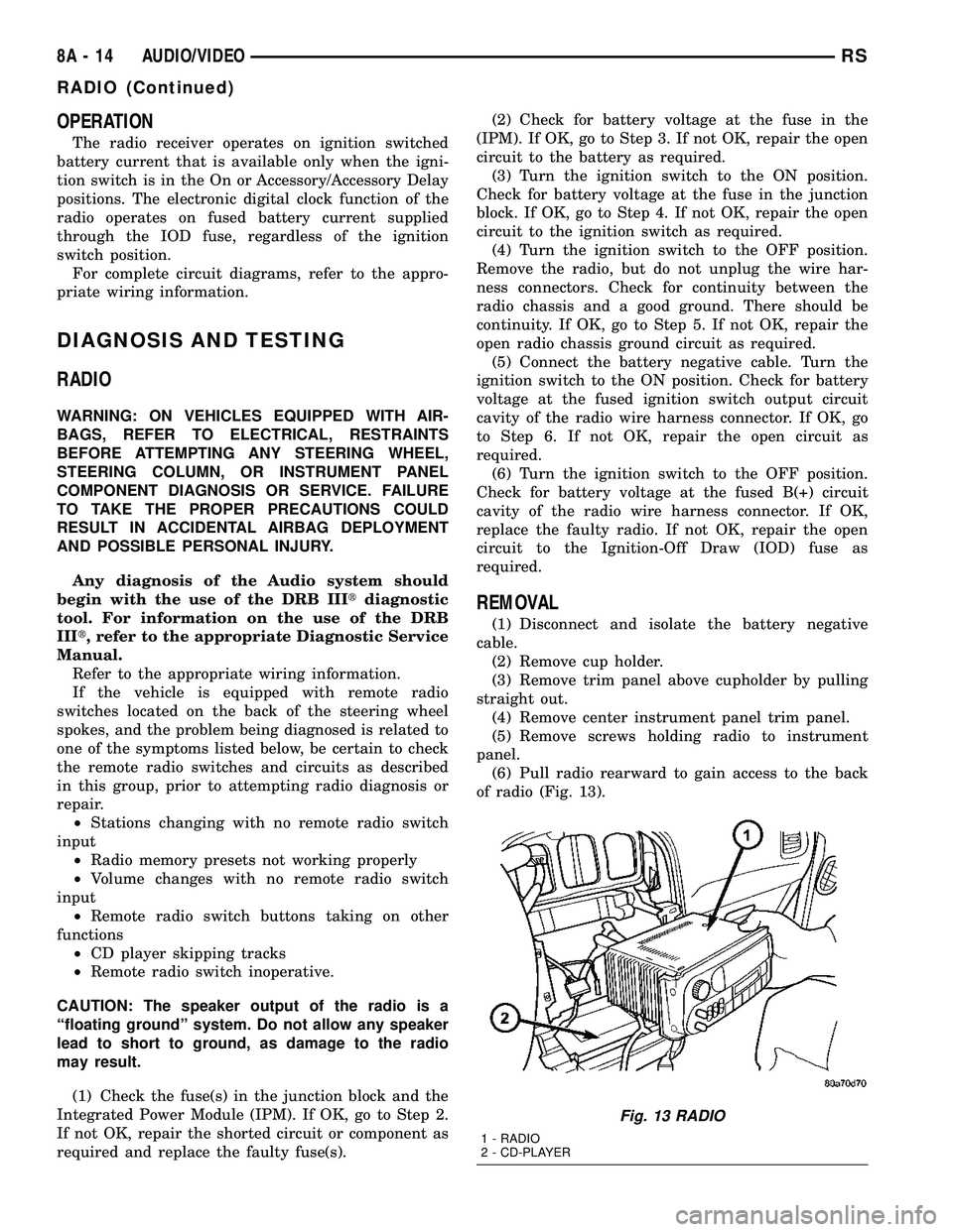
of radio (Fig. 13).
Fig. 13 RADIO
1 - RADIO
2 - CD-PLAYER
8A - 14 AUDIO/VIDEORS
RADIO (Continued)
Page 320 of 2339
(2) Wearing safety glasses, look through the bat-
tery cell cap holes to determine the level of the elec-
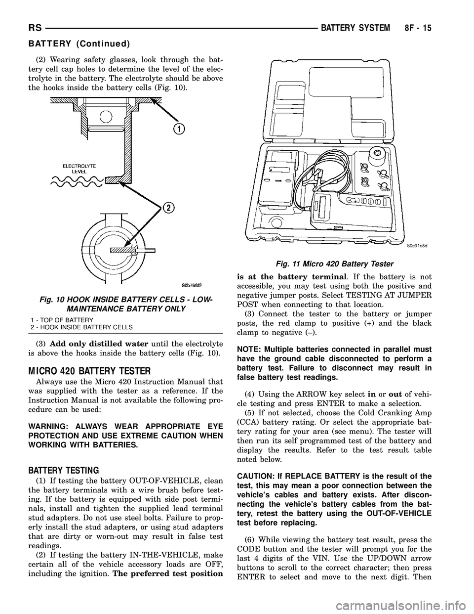
trolyte in the battery. The electrolyte should be above
the hooks inside the battery cells (Fig. 10).
(3)Add only distilled wateruntil the electrolyte
is above the hooks inside the battery cells (Fig. 10).
MICRO 420 BATTERY TESTER
Always use the Micro 420 Instruction Manual that
was supplied with the tester as a reference. If the
Instruction Manual is not available the following pro-
cedure can be used:
WARNING: ALWAYS WEAR APPROPRIATE EYE
PROTECTION AND USE EXTREME CAUTION WHEN
WORKING WITH BATTERIES.
BATTERY TESTING
(1) If testing the battery OUT-OF-VEHICLE, clean
the battery terminals with a wire brush before test-
ing. If the battery is equipped with side post termi-
nals, install and tighten the supplied lead terminal
stud adapters. Do not use steel bolts. Failure to prop-
erly install the stud adapters, or using stud adapters
that are dirty or worn-out may result in false test
readings.
(2) If testing the battery IN-THE-VEHICLE, make
certain all of the vehicle accessory loads are OFF,
including the ignition.The preferred test positionis at the battery terminal. If the battery is not
accessible, you may test using both the positive and
negative jumper posts. Select TESTING AT JUMPER
POST when connecting to that location.
(3) Connect the tester to the battery or jumper
posts, the red clamp to positive (+) and the black
clamp to negative (±).
NOTE: Multiple batteries connected in parallel must
have the ground cable disconnected to perform a
battery test. Failure to disconnect may result in
false battery test readings.
(4) Using the ARROW key selectinoroutof vehi-
cle testing and press ENTER to make a selection.
(5) If not selected, choose the Cold Cranking Amp
(CCA) battery rating. Or select the appropriate bat-
tery rating for your area (see menu). The tester will
then run its self programmed test of the battery and
display the results. Refer to the test result table
noted below.
CAUTION: If REPLACE BATTERY is the result of the
test, this may mean a poor connection between the
vehicle's cables and battery exists. After discon-
necting the vehicle's battery cables from the bat-
tery, retest the battery using the OUT-OF-VEHICLE
test before replacing.
(6) While viewing the battery test result, press the
CODE button and the tester will prompt you for the
last 4 digits of the VIN. Use the UP/DOWN arrow
buttons to scroll to the correct character; then press
ENTER to select and move to the next digit. Then
Fig. 10 HOOK INSIDE BATTERY CELLS - LOW-
MAINTENANCE BATTERY ONLY
1 - TOP OF BATTERY
2 - HOOK INSIDE BATTERY CELLS
Fig. 11 Micro 420 Battery Tester
RSBATTERY SYSTEM8F-15
BATTERY (Continued)
Page 413 of 2339
SELF-DIAGNOSTIC TEST
A self-diagnostic test is used to determine that the
electronics module is operating properly, and that all
the PCI data bus messages are being received for ini-
tial operation. Initiate the self-diagnostic test as fol-
lows:
(1) With the ignition switch in the Off position, on
Electronic Vehicle Information Center (EVIC) and
Compass Mini-Trip Computer (CMTC) equipped vehi-
cles simultaneously depress and hold theSTEPand
theRESETbuttons. On Compass Temperature Mod-
ule (CT) equipped vehicles depress theC/Tand the
US/Mpush buttons.
(2) Turn the ignition switch to the On position.
(3) Following completion of these tests, the elec-
tronics module will display one of the following mes-
sages:
a.Pass Self Test (EVIC only), PASS (CT,
CMTC)- The electronics module is working properly.
b.Failed Self Test (EVIC only), FAIL (CT,
CMTC)- The electronics module has an internal fail-
ure. The electronics module is faulty and must be
replaced.
NOTE: If the compass functions, but accuracy is
suspect, it may be necessary to perform a variation
adjustment. This procedure allows the compass
unit to accommodate variations in the earth's mag-
netic field strength, based on geographic location.
(Refer to 8 - ELECTRICAL/OVERHEAD CONSOLE -
STANDARD PROCEDURE - COMPASS VARIATION
ADJUSTMENT).
NOTE: If the compass reading display is blank and
only ªCALº appears in the display, demagnetizing
may be necessary to remove excessive residual
magnetic fields from the vehicle. (Refer to 8 - ELEC-
TRICAL/OVERHEAD CONSOLE - STANDARD PRO-
CEDURE - COMPASS DEMAGNETIZING).
STANDARD PROCEDURE
COMPASS CALIBRATION
CAUTION: Do not place any external magnets, such
as magnetic roof mount antennas, in the vicinity of
the compass. Do not use magnetic tools when ser-
vicing the overhead console.The electronic compass unit features a self-cali-
brating design, which simplifies the calibration pro-
cedure. This feature automatically updates the
compass calibration while the vehicle is being driven.
This allows the compass unit to compensate for small
changes in the residual magnetism the vehicle may
acquire during normal use. If the compass readings
appear to be erratic or out of calibration, perform the
following calibration procedure. Also, new service
replacement Electronic Modules (EVIC, CMTC, CT)
must have their compass calibrated using this proce-
dure. Do not attempt to calibrate the compass near
large metal objects such as other vehicles, large
buildings, or bridges; or, near overhead or under-
ground power lines.
NOTE: Whenever the compass is calibrated manu-
ally, the variance number must also be reset. (Refer
to 8 - ELECTRICAL/OVERHEAD CONSOLE - STAN-
DARD PROCEDURE - COMPASS VARIATION
ADJUSTMENT).
Calibrate the compass manually as follows:
(1) Turn the ignition switch to the On position. If
the compass/thermometer data is not currently being
displayed, momentarily depress and release the C/T
push button to reach the compass/thermometer dis-
play.
(2) On Electronic Vehicle Information Center
(EVIC) and Compass Mini-Trip Computer (CMTC)
equipped vehicles depress the Reset push button and
hold the button until ªCALº appears in the display.
This takes about ten seconds, and appears about five
seconds after ªVAR = XXº is displayed. On Compass
Temperature Module (CT) equipped vehicles depress
the C/T push button and US/M push button down
until ªCALº appears in the display. This takes about
ten seconds, and appears about five seconds after
ªVAR = XXº is displayed.
(3) Release the push button(s).
(4) Drive the vehicle on a level surface, away from
large metal objects and power lines, through three or
more complete circles at between five and eight kilo-
meters-per-hour (three and five miles-per-hour) for a
minimum of 48 seconds. The ªCALº message will dis-
appear from the display to indicate that the compass
is now calibrated.
NOTE: If the ªCALº message remains in the display,
either there is excessive magnetism near the com-
pass, or the unit is faulty. Repeat the calibration
procedure one more time.
8M - 4 OVERHEAD CONSOLERS
OVERHEAD CONSOLE (Continued)
Page 416 of 2339
(2) Connect the EVIC, CMTC or CT electronic
module and the reading/courtesy lamps electrical
connector.
(3) Using your fingertips, grasp the sides of the
overhead console and push straight up evenly to
engage the two snap clips at the rear of the unit.
CAUTION: DO NOT PRESS ON THE SUNGLASS
STORAGE BIN DOOR. DAMAGE TO THE DOOR MAY
RESULT.
(4) Install the overhead console retaining screw,
located in the front of console. Torque the screw to
1.2 N´m (10 in. lbs.).
(5) Connect the remote negative battery cable.
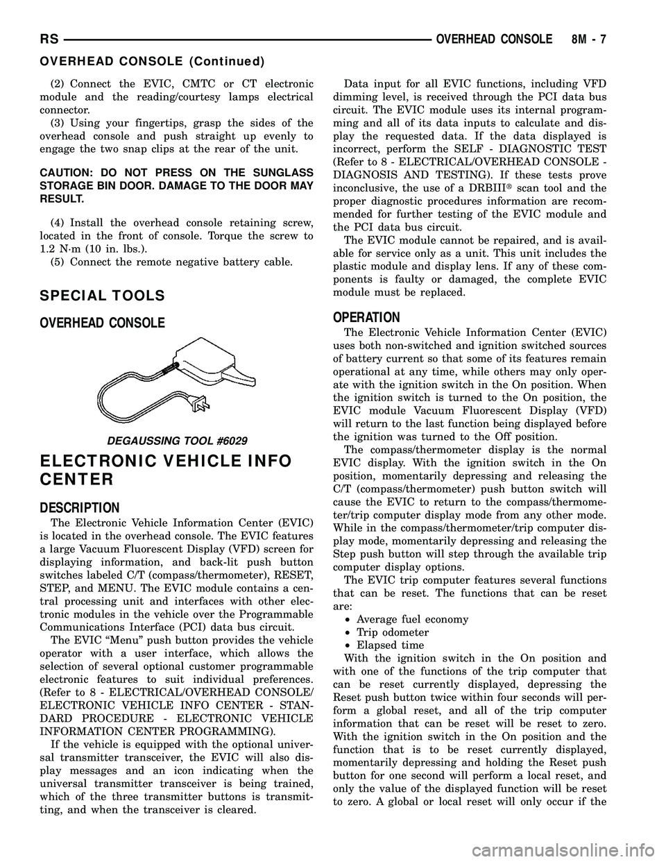
SPECIAL TOOLS
OVERHEAD CONSOLE
ELECTRONIC VEHICLE INFO
CENTER
DESCRIPTION
The Electronic Vehicle Information Center (EVIC)
is located in the overhead console. The EVIC features
a large Vacuum Fluorescent Display (VFD) screen for
displaying information, and back-lit push button
switches labeled C/T (compass/thermometer), RESET,
STEP, and MENU. The EVIC module contains a cen-
tral processing unit and interfaces with other elec-
tronic modules in the vehicle over the Programmable
Communications Interface (PCI) data bus circuit.
The EVIC ªMenuº push button provides the vehicle
operator with a user interface, which allows the
selection of several optional customer programmable
electronic features to suit individual preferences.
(Refer to 8 - ELECTRICAL/OVERHEAD CONSOLE/
ELECTRONIC VEHICLE INFO CENTER - STAN-
DARD PROCEDURE - ELECTRONIC VEHICLE
INFORMATION CENTER PROGRAMMING).
If the vehicle is equipped with the optional univer-
sal transmitter transceiver, the EVIC will also dis-
play messages and an icon indicating when the
universal transmitter transceiver is being trained,
which of the three transmitter buttons is transmit-
ting, and when the transceiver is cleared.Data input for all EVIC functions, including VFD
dimming level, is received through the PCI data bus
circuit. The EVIC module uses its internal program-
ming and all of its data inputs to calculate and dis-
play the requested data. If the data displayed is
incorrect, perform the SELF - DIAGNOSTIC TEST
(Refer to 8 - ELECTRICAL/OVERHEAD CONSOLE -
DIAGNOSIS AND TESTING). If these tests prove
inconclusive, the use of a DRBIIItscan tool and the
proper diagnostic procedures information are recom-
mended for further testing of the EVIC module and
the PCI data bus circuit.
The EVIC module cannot be repaired, and is avail-
able for service only as a unit. This unit includes the
plastic module and display lens. If any of these com-
ponents is faulty or damaged, the complete EVIC
module must be replaced.
OPERATION
The Electronic Vehicle Information Center (EVIC)
uses both non-switched and ignition switched sources
of battery current so that some of its features remain
operational at any time, while others may only oper-
ate with the ignition switch in the On position. When
the ignition switch is turned to the On position, the
EVIC module Vacuum Fluorescent Display (VFD)
will return to the last function being displayed before
the ignition was turned to the Off position.
The compass/thermometer display is the normal
EVIC display. With the ignition switch in the On
position, momentarily depressing and releasing the
C/T (compass/thermometer) push button switch will
cause the EVIC to return to the compass/thermome-
ter/trip computer display mode from any other mode.
While in the compass/thermometer/trip computer dis-
play mode, momentarily depressing and releasing the
Step push button will step through the available trip
computer display options.
The EVIC trip computer features several functions
that can be reset. The functions that can be reset
are:
²Average fuel economy
²Trip odometer
²Elapsed time
With the ignition switch in the On position and
with one of the functions of the trip computer that
can be reset currently displayed, depressing the
Reset push button twice within four seconds will per-
form a global reset, and all of the trip computer
information that can be reset will be reset to zero.
With the ignition switch in the On position and the
function that is to be reset currently displayed,
momentarily depressing and holding the Reset push
button for one second will perform a local reset, and
only the value of the displayed function will be reset
to zero. A global or local reset will only occur if the
DEGAUSSING TOOL #6029
RSOVERHEAD CONSOLE8M-7
OVERHEAD CONSOLE (Continued)
Page 418 of 2339
²RETRAIN TIRE SENSORS?- This program-
mable feature only applies to vehicles equipped with
the optional Tire Pressure Monitoring System. The
options include Yes and No. The default is No. When
Yes is selected, and the menu button is depressed the
EVIC will enter the training mode, starting with the
left front tire.
²USE FACTORY SETTINGS?- The options
include Yes and No. The default is Yes. When yes is
selected all the programmable features will return to
there defaults and the rest of the programmable fea-
tures will not be displayed. If No is selected the rest
of the programmable features will be displayed at
there current chosen values. This feature will auto-
matically return to the Yes default under two condi-
tions. First, if no programmable features are changed
from there defaults. Second, if all the programmable
features equal there defaults.
²AUTO DOOR LOCKS?- The options include
Yes and No. The default is Yes. When Yes is selected,
all doors and the liftgate lock automatically when
vehicle speed reaches 25 kilometers-per-hour (15
miles-per-hour). If YES is selected, a second program-
mable feature appears,AUTO UNLOCK ON EXIT?
- The options again include Yes and No. The default
is No. When Yes is selected, following each Auto Door
Lock event all doors and the liftgate will automati-
cally unlock when the driver door is opened, if the
vehicle is stopped and the transmission gear selector
is in Park or Neutral. The Auto Door Unlock event
will only occur once following each Auto Door Lock
event.
²REMOTE UNLOCK- The options include
Driver Door 1st and All Doors. The default is Driver
Door 1st. When Diver Door 1st is selected, only the
driver door unlocks when the Unlock button of the
Remote Keyless Entry (RKE) transmitter is
depressed once. The Unlock button of the RKE trans-
mitter must be depressed twice to unlock all doors.
When All Doors is selected, all doors unlock when the
Unlock button of the RKE transmitter is depressed
once.
²REMOTE LINKED TO MEMORY?- This pro-
grammable feature only applies to vehicles equipped
with the optional memory / heated system. The
options include Yes and No. The default is No. When
Yes is selected, the memory system will recall the
Driver 1 or Driver 2 memory settings assigned to the
RKE transmitter being used to unlock the vehicle.
When No is selected, the memory system will only
recall memory settings when the Driver 1 or Driver 2
push buttons of the memory switch on the driver side
front door trim panel are depressed.
²SOUND HORN ON LOCK?- The options
include Yes and No. The default is No. When Yes is
selected, a short horn chirp will provide an audibleconfirmation when the RKE receiver recognizes a
valid Lock signal from an RKE transmitter. When No
is selected, no horn chirp will occur with the RKE
Lock event. This feature may be selected indepen-
dent of theFLASH LIGHTS WITH LOCKS?pro-
grammable feature.
²FLASH LIGHTS WITH LOCKS?- The options
include Yes and No. The default is Yes. When Yes is
selected, a single flash of the hazard warning lamps
will provide an optical confirmation when the RKE
receiver recognizes a valid Lock signal from an RKE
transmitter, and two flashes of the same lamps will
occur when the RKE receiver recognizes a valid
Unlock signal from an RKE transmitter. When No is
selected, no lamp flash will occur with the RKE Lock
or Unlock event. This feature may be selected inde-
pendent of theSOUND HORN ON LOCK?pro-
grammable feature.
²HEADLAMP DELAY =- The options include
Off, 30 Sec, 60 Sec, and 90 Sec. The default is 90 Sec.
When a time interval is selected, the headlamps will
remain on for that length of time when the head-
lamps are turned off after the ignition is turned off,
or if the Auto mode is selected on vehicles with the
Auto Headlamps option. When Off is selected, the
headlamp delay feature is disabled.
²HEADLAMPS ON WITH WIPERS?- This pro-
grammable feature only applies to vehicles equipped
with the optional Auto Headlamps. The options
include Yes and No. The default is No. When Yes is
selected, the headlamps will turn on automatically
when the windshield wipers are turned on. The head-
lamps will turn off when the wipers are turned off,
as long as the headlamp switch is in the Auto or Off
positions. When No is selected, the headlamps will
only turn on if manually selected or if the Auto mode
is selected and the outside ambient light levels dic-
tate that they should be on.
²POWER ACCESSORY DELAY?- The options
include Yes and No. The default is Yes. When No is
selected, the accessory powered components will turn
off automatically when the ignition key is turned off.
When Yes is selected, the accessory powered compo-
nents will remain on for 45 seconds when the igni-
tion key is turned off.
REMOVAL
(1) Disconnect and isolate the battery negative
cable.
(2) Remove overhead console. (Refer to 8 - ELEC-
TRICAL/OVERHEAD CONSOLE - REMOVAL).
(3) Remove the ten screws holding the Electronic
Vehicle Information Center (EVIC) module in the
overhead console.
(4) Remove EVIC module from console assembly.
RSOVERHEAD CONSOLE8M-9
ELECTRONIC VEHICLE INFO CENTER (Continued)
Page 419 of 2339

NOTE: If the EVIC module is being replaced, the tire
pressure monitoring system (if equipped) must be
retrained. (Refer to 22 - TIRES/WHEELS/TIRE PRES-
SURE MONITORING/SENSOR - STANDARD PROCE-
DURE)
INSTALLATION
(1) Position the Electronic Vehicle Information
Center (EVIC) module in the overhead console.
(2) Install the ten screws holding the EVIC module
in the overhead console.
(3) Install the overhead console (Refer to 8 -
ELECTRICAL/OVERHEAD CONSOLE - INSTALLA-
TION).
(4) Connect the battery negative cable.
NOTE: If the EVIC module is being replaced, the tire
pressure monitoring system (if equipped) must be
retrained. (Refer to 22 - TIRES/WHEELS/TIRE PRES-
SURE MONITORING/SENSOR - STANDARD PROCE-
DURE).
NOTE: If a new EVIC module has been installed, the
compass will have to be calibrated and the variance
set. (Refer to 8 - ELECTRICAL/OVERHEAD CON-
SOLE - STANDARD PROCEDURE - COMPASS CAL-
IBRATION).
COMPASS/MINI-TRIP
COMPUTER
DESCRIPTION
The Compass Mini-Trip Computer (CMTC) module
is located in the overhead console. The CMTC con-
sists of a electronic control module with a vacuum
fluorescent display (VFD) and function switches. The
CMTC consists of a electronic module that displays
compass, trip computer, and temperature features.
Actuating the STEP push button will cause the
CMTC to change mode of operation when the ignition
is ON. Example:
²Average miles per gallon (ECO)
²Distance to empty (DTE)
²Instant miles per gallon (ECO)
²Trip odometer (ODO)
²Elapsed time (ET)
²Blank
Actuating the C/T push button will cause the
CMTC to change to the Compass/Temperature dis-
play.
OPERATION
The Compass Mini-Trip Computer (CMTC) module
in the overhead console has buttons used to select
various functions. The CMTC selector buttons will
not operate until the ignition is in the RUN position.
When the ignition switch is first turned to the
RUN position the CMTC display;
²Blanks momentarily
²All segments of the VFD will light for one sec-
ond
²Blanks momentarily
²Returns to the last mode setting selected before
the ignition was last switched OFF.
DIAGNOSIS AND TESTING
COMPASS MINI-TRIP COMPUTER
Any diagnosis of the compass mini-trip com-
puter should begin with the use of the DRB IIIt
diagnostic tool. For information on the use of
the DRB IIIt, refer to the appropriate Diagnos-
tic Procedures information.
Compass Mini-Trip Computer (CMTC) data is
obtained from the Body Control Module (BCM) on
the Programmable Communications Interface (PCI)
Data Bus circuit. The CMTC will display dashes (- -)
for any of the screens it did not receive the bus mes-
sages. The label corresponding to the missing infor-
mation will be lit. If no CMTC data is displayed,
check the PCI Data Bus circuit communications and
the BCM. If the dimming level is improper check the
PCI Data Bus circuit.
REMOVAL
(1) Disconnect and isolate the battery negative
cable.
(2) Remove overhead console(Refer to 8 - ELEC-
TRICAL/OVERHEAD CONSOLE - REMOVAL).
(3) Remove the screws holding Compass Mini-Trip
Computer (CMTC) module in the overhead console.
(4) Remove CMTC module from the console assem-
bly.
INSTALLATION
(1) Position the compass mini-trip computer
(CMTC) module in the overhead console.
(2) Install the ten screws holding the CMTC mod-
ule in the overhead console.
(3) Install the overhead console (Refer to 8 -
ELECTRICAL/OVERHEAD CONSOLE - INSTALLA-
TION).
(4) Connect the battery negative cable.
8M - 10 OVERHEAD CONSOLERS
ELECTRONIC VEHICLE INFO CENTER (Continued)
Page 420 of 2339
NOTE: If a new CMTC module has been installed,
the compass will have to be calibrated and the vari-
ance set. (Refer to 8 - ELECTRICAL/OVERHEAD
CONSOLE - STANDARD PROCEDURE - COMPASS
CALIBRATION).
UNIVERSAL TRANSMITTER
DESCRIPTION
A Universal Transmitter transceiver is available on
some vehicles. The universal transmitter transceiver
is integral to the Electronic Vehicle Information Cen-
ter (EVIC) and the Compass Mini-Trip Computer
(CMTC) modules, which are located in the overhead
console. The only visible component of the universal
transmitter are the three transmitter push buttons
centered between the modules push buttons located
just rearward of the display screen in the overhead
console. The three universal transmitter push but-
tons are identified with one, two or three light indi-
cators so that they can be easily identified.
Each of the three universal transmitter push but-
tons controls an independent radio transmitter chan-
nel. Each of these three channels can be trained to
transmit a different radio frequency signal for the
remote operation of garage door openers, motorized
gate openers, home or office lighting, security sys-
tems or just about any other device that can be
equipped with a radio receiver in the 286 to 399
MegaHertz (MHz) frequency range for remote opera-
tion. The universal transmitter is capable of operat-
ing systems using either rolling code or non-rolling
code technology.
The electronics module displays messages and a
small house-shaped icon with one, two or three dots
corresponding to the three transmitter buttons to
indicate the status of the universal transmitter. The
EVIC messages are:
²Cleared Channels- Indicates that all of the
transmitter codes stored in the universal transmitter
have been successfully cleared.
²Training- Indicates that the universal trans-
mitter is in its transmitter learning mode.
²Trained- Indicates that the universal transmit-
ter has successfully acquired a new transmitter code.
²Transmit- Indicates that a trained universal
transmitter button has been depressed and that the
universal transmitter is transmitting.
The universal transmitter cannot be repaired, and
is available for service only as a unit with the EVIC
or CMTC modules. If any of these components is
faulty or damaged, the complete EVIC or CMTC
module must be replaced.
DIAGNOSIS AND TESTING
UNIVERSAL TRANSMITTER
If both the Universal Transmitter and the Elec-
tronic Vehicle Information Center (EVIC) are inoper-
ative, (Refer to 8 - ELECTRICAL/OVERHEAD
CONSOLE/ELECTRONIC VEHICLE INFO CENTER
- DIAGNOSIS AND TESTING). If the Universal
Transmitter is inoperative, but the EVIC is operating
normally, retrain the Transmitter with a known good
transmitter (Refer to 8 - ELECTRICAL/OVERHEAD
CONSOLE/UNIVERSAL TRANSMITTER - STAN-
DARD PROCEDURE - SETTING TRANSMITTER
CODES). If the unit is still inoperative, test the uni-
versal transmitter with the Radio Frequency Detec-
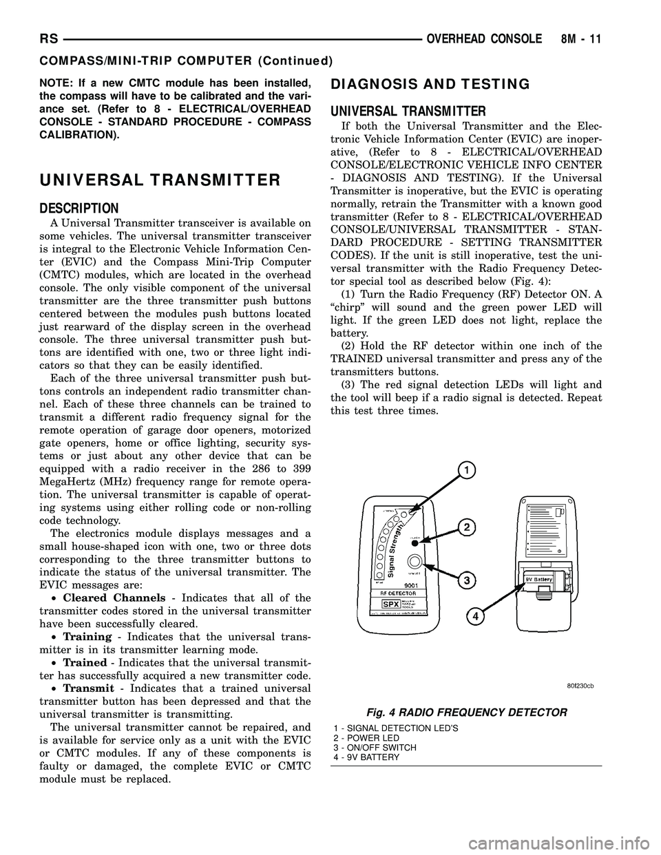
tor special tool as described below (Fig. 4):
(1) Turn the Radio Frequency (RF) Detector ON. A
ªchirpº will sound and the green power LED will
light. If the green LED does not light, replace the
battery.
(2) Hold the RF detector within one inch of the
TRAINED universal transmitter and press any of the
transmitters buttons.
(3) The red signal detection LEDs will light and
the tool will beep if a radio signal is detected. Repeat
this test three times.
Fig. 4 RADIO FREQUENCY DETECTOR
1 - SIGNAL DETECTION LED'S
2 - POWER LED
3 - ON/OFF SWITCH
4 - 9V BATTERY
RSOVERHEAD CONSOLE8M-11
COMPASS/MINI-TRIP COMPUTER (Continued)