buttons CHRYSLER VOYAGER 2005 User Guide
[x] Cancel search | Manufacturer: CHRYSLER, Model Year: 2005, Model line: VOYAGER, Model: CHRYSLER VOYAGER 2005Pages: 2339, PDF Size: 59.69 MB
Page 421 of 2339
STANDARD PROCEDURE
SETTING TRANSMITTER CODES
(1) Turn off the engine.
(2) Erase the codes by pressing the two outside
buttons. Release the buttons when the display con-
firms the operation (about 20 seconds).
(3) Choose one of the three buttons to train. Place
the hand-held transmitter within one inch of the uni-
versal transmitter and push the buttons on both
transmitters.
(4) Release both buttons. Your universal transmit-
ter is now ªtrainedº. To train the other buttons,
repeat Step 3 and Step 4. Be sure to keep your hand-
held transmitter in case you need to retrain the uni-
versal transmitter.
ERASING TRANSMITTER CODES
To erase the universal transmitter codes, simply
hold down the two outside buttons until the display
confirms the operation.
NOTE: Individual channels cannot be erased. Eras-
ing the transmitter codes will erase ALL pro-
grammed codes.
REMOVAL
(1) For the universal transmitter removal proce-
dure, (Refer to 8 - ELECTRICAL/OVERHEAD CON-
SOLE/COMPASS/MINI-TRIP COMPUTER -
REMOVAL.
AMBIENT TEMP SENSOR
DESCRIPTION
Ambient air temperature is monitored by the over-
head console through ambient temperature messages
received from the Powertrain Control Module (PCM)
over the Programmable Communications Interface
(PCI) data bus circuit. The PCM receives a hard
wired input from the ambient temperature sensor.
The ambient temperature sensor is a variable resis-
tor mounted to a bracket that is secured with a screw
to the right side of the headlamp mounting module
grille opening, behind the radiator grille and in front
of the engine compartment.
For additional information on the PCM, (Refer to 8
- ELECTRICAL/ELECTRONIC CONTROL MOD-
ULES/POWERTRAIN CONTROL MODULE -
DESCRIPTION).
OPERATION
The ambient temperature sensor is a variable
resistor that operates on a five-volt reference signal
sent by the Powertrain Control Module (PCM). The
resistance in the sensor changes as temperature
changes, changing the temperature sensor signal cir-
cuit voltage to the PCM. Based upon the resistance
in the sensor, the PCM senses a specific voltage on
the temperature sensor signal circuit, which it is pro-
grammed to correspond to a specific temperature.
The PCM then sends the proper ambient tempera-
ture messages to the Electronic Vehicle Information
Center (EVIC)/Compass Mini-Trip Computer (CMTC)
over the Programmable Communication Interface
(PCI) data bus.
The thermometer function is supported by the
ambient temperature sensor, a wiring circuit, the
PCM, the PCI data bus, and the Electronics module.
If any portion of the ambient temperature sensor cir-
cuit fails, the PCM will self-diagnose the circuit.
The ambient temperature sensor circuit can also be
diagnosed manually (Refer to 8 - ELECTRICAL/
OVERHEAD CONSOLE/AMBIENT TEMP SENSOR
- DIAGNOSIS AND TESTING - AMBIENT TEM-
PERATURE SENSOR CIRCUIT). If the temperature
sensor and circuit are confirmed to be OK, but the
temperature display is inoperative or incorrect,
(Refer to 8 - ELECTRICAL/OVERHEAD CONSOLE -
DIAGNOSIS AND TESTING) to determine the cause.
For complete circuit diagrams, refer to the appropri-
ate wiring information.
DIAGNOSIS AND TESTING
AMBIENT TEMPERATURE SENSOR
(1) Turn the ignition switch to the Off position.
Disconnect and isolate the battery negative cable.
Disconnect the ambient temperature sensor wire har-
ness connector.
(2) Measure the resistance of the ambient temper-
ature sensor. At room temperature (approx. 68ÉF),
the sensor resistance should be between 10-13 Kilo-
hms. The sensor resistance should be between these
two values at 68ÉF. If the resistance is out of range
replace the ambient temperature sensor.
AMBIENT TEMPERATURE SENSOR CIRCUIT
(1) Turn the ignition switch to the Off position.
Disconnect and isolate the battery negative cable.
Disconnect the ambient temperature sensor wire har-
ness connector and the Powertrain Control Module
(PCM) wire harness connector.
8M - 12 OVERHEAD CONSOLERS
UNIVERSAL TRANSMITTER (Continued)
Page 447 of 2339
KEYLESS ENTRY
TRANSMITTER
DIAGNOSIS AND TESTING
KEYLESS ENTRY TRANSMITTER
Using special tool 9001, first test to ensure that
the transmitter is functioning. Typical testing dis-
tance is 2.5 centimeters (1 inch) for Asian transmit-
ters and 30.5 centimeters (12 inches) for all others.
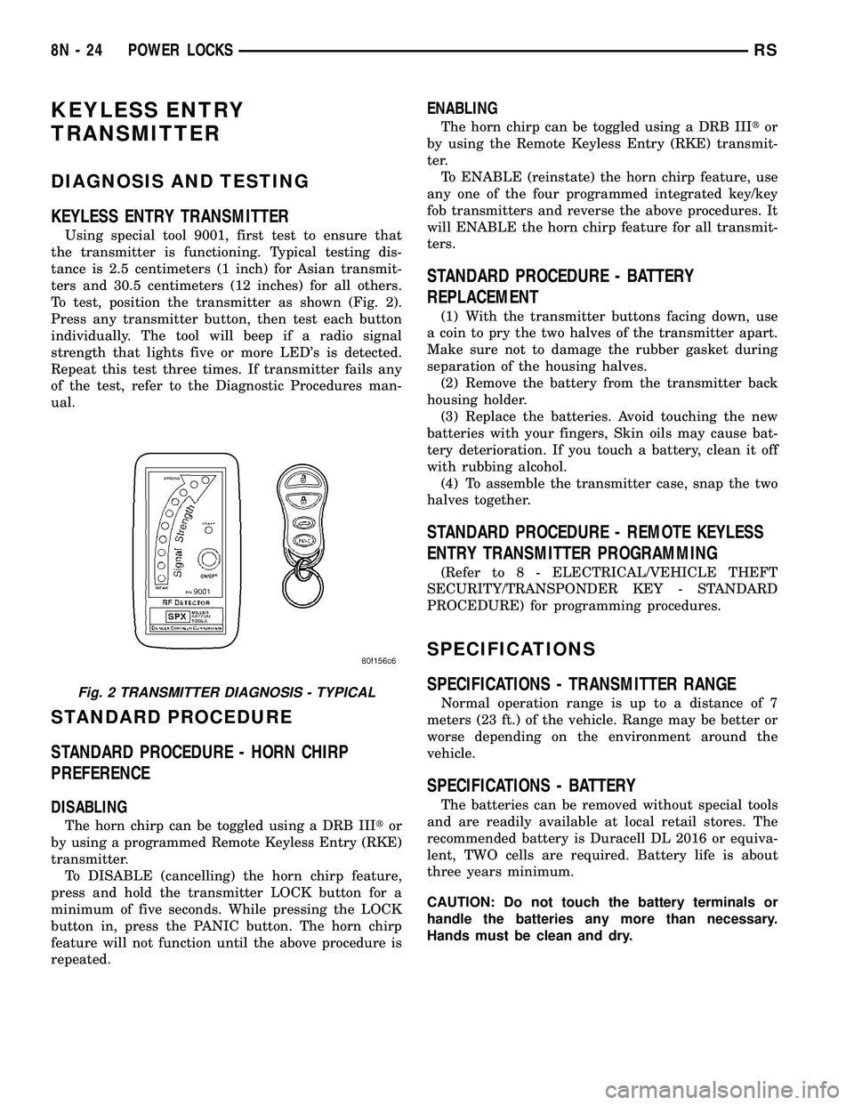
To test, position the transmitter as shown (Fig. 2).
Press any transmitter button, then test each button
individually. The tool will beep if a radio signal
strength that lights five or more LED's is detected.
Repeat this test three times. If transmitter fails any
of the test, refer to the Diagnostic Procedures man-
ual.
STANDARD PROCEDURE
STANDARD PROCEDURE - HORN CHIRP
PREFERENCE
DISABLING
The horn chirp can be toggled using a DRB IIItor
by using a programmed Remote Keyless Entry (RKE)
transmitter.
To DISABLE (cancelling) the horn chirp feature,
press and hold the transmitter LOCK button for a
minimum of five seconds. While pressing the LOCK
button in, press the PANIC button. The horn chirp
feature will not function until the above procedure is
repeated.
ENABLING
The horn chirp can be toggled using a DRB IIItor
by using the Remote Keyless Entry (RKE) transmit-
ter.
To ENABLE (reinstate) the horn chirp feature, use
any one of the four programmed integrated key/key
fob transmitters and reverse the above procedures. It
will ENABLE the horn chirp feature for all transmit-
ters.
STANDARD PROCEDURE - BATTERY
REPLACEMENT
(1) With the transmitter buttons facing down, use
a coin to pry the two halves of the transmitter apart.
Make sure not to damage the rubber gasket during
separation of the housing halves.
(2) Remove the battery from the transmitter back
housing holder.
(3) Replace the batteries. Avoid touching the new
batteries with your fingers, Skin oils may cause bat-
tery deterioration. If you touch a battery, clean it off
with rubbing alcohol.
(4) To assemble the transmitter case, snap the two
halves together.
STANDARD PROCEDURE - REMOTE KEYLESS
ENTRY TRANSMITTER PROGRAMMING
(Refer to 8 - ELECTRICAL/VEHICLE THEFT
SECURITY/TRANSPONDER KEY - STANDARD
PROCEDURE) for programming procedures.
SPECIFICATIONS
SPECIFICATIONS - TRANSMITTER RANGE
Normal operation range is up to a distance of 7
meters (23 ft.) of the vehicle. Range may be better or
worse depending on the environment around the
vehicle.
SPECIFICATIONS - BATTERY
The batteries can be removed without special tools
and are readily available at local retail stores. The
recommended battery is Duracell DL 2016 or equiva-
lent, TWO cells are required. Battery life is about
three years minimum.
CAUTION: Do not touch the battery terminals or
handle the batteries any more than necessary.
Hands must be clean and dry.
Fig. 2 TRANSMITTER DIAGNOSIS - TYPICAL
8N - 24 POWER LOCKSRS
Page 459 of 2339
REMOVAL
(1) Disconnect and isolate the battery negative
cable.
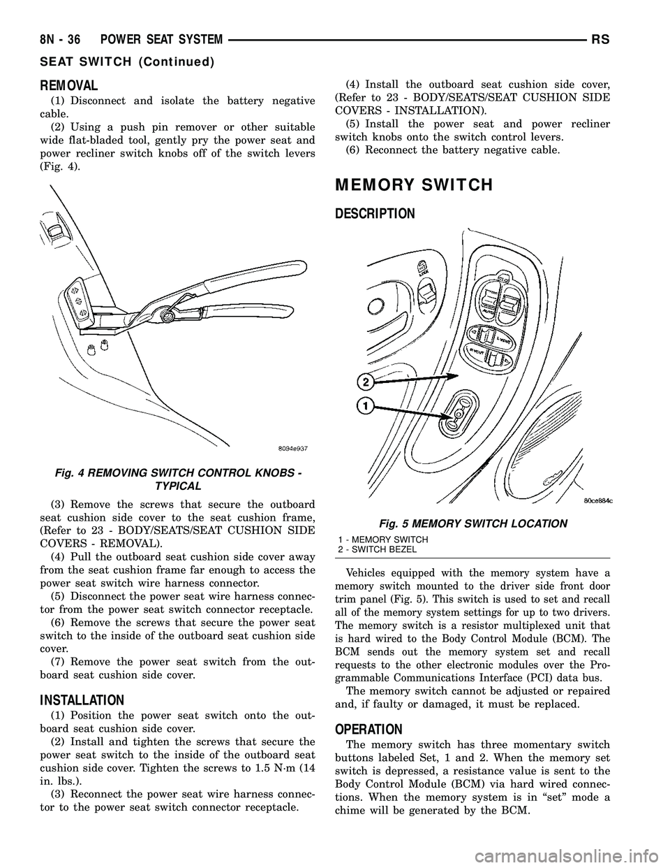
(2) Using a push pin remover or other suitable
wide flat-bladed tool, gently pry the power seat and
power recliner switch knobs off of the switch levers
(Fig. 4).
(3) Remove the screws that secure the outboard
seat cushion side cover to the seat cushion frame,
(Refer to 23 - BODY/SEATS/SEAT CUSHION SIDE
COVERS - REMOVAL).
(4) Pull the outboard seat cushion side cover away
from the seat cushion frame far enough to access the
power seat switch wire harness connector.
(5) Disconnect the power seat wire harness connec-
tor from the power seat switch connector receptacle.
(6) Remove the screws that secure the power seat
switch to the inside of the outboard seat cushion side
cover.
(7) Remove the power seat switch from the out-
board seat cushion side cover.
INSTALLATION
(1) Position the power seat switch onto the out-
board seat cushion side cover.
(2) Install and tighten the screws that secure the
power seat switch to the inside of the outboard seat
cushion side cover. Tighten the screws to 1.5 N´m (14
in. lbs.).
(3) Reconnect the power seat wire harness connec-
tor to the power seat switch connector receptacle.(4) Install the outboard seat cushion side cover,
(Refer to 23 - BODY/SEATS/SEAT CUSHION SIDE
COVERS - INSTALLATION).
(5) Install the power seat and power recliner
switch knobs onto the switch control levers.
(6) Reconnect the battery negative cable.
MEMORY SWITCH
DESCRIPTION
Vehicles equipped with the memory system have a
memory switch mounted to the driver side front door
trim panel (Fig. 5). This switch is used to set and recall
all of the memory system settings for up to two drivers.
The memory switch is a resistor multiplexed unit that
is hard wired to the Body Control Module (BCM). The
BCM sends out the memory system set and recall
requests to the other electronic modules over the Pro-
grammable Communications Interface (PCI) data bus.
The memory switch cannot be adjusted or repaired
and, if faulty or damaged, it must be replaced.
OPERATION
The memory switch has three momentary switch
buttons labeled Set, 1 and 2. When the memory set
switch is depressed, a resistance value is sent to the
Body Control Module (BCM) via hard wired connec-
tions. When the memory system is in ªsetº mode a
chime will be generated by the BCM.
Fig. 4 REMOVING SWITCH CONTROL KNOBS -
TYPICAL
Fig. 5 MEMORY SWITCH LOCATION
1 - MEMORY SWITCH
2 - SWITCH BEZEL
8N - 36 POWER SEAT SYSTEMRS
SEAT SWITCH (Continued)
Page 532 of 2339
SPEED CONTROL
TABLE OF CONTENTS
page page
SPEED CONTROL
DESCRIPTION..........................1
OPERATION
OPERATION..........................1
OPERATION - INTERACTIVE SPEED
CONTROL (4 Speed EATX Only)...........2
DIAGNOSIS AND TESTING - ROAD TEST.....3
SPECIFICATIONS - TORQUE...............3
CABLE
DESCRIPTION..........................4
OPERATION............................4
REMOVAL.............................4
INSTALLATION..........................4
SERVO
DESCRIPTION..........................4OPERATION............................4
REMOVAL.............................4
INSTALLATION..........................4
SWITCH
DESCRIPTION..........................5
OPERATION............................5
REMOVAL.............................5
INSTALLATION..........................6
VACUUM RESERVOIR
DESCRIPTION..........................6
OPERATION............................6
REMOVAL.............................6
INSTALLATION..........................6
SPEED CONTROL
DESCRIPTION
The speed control system is electronically con-
trolled and vacuum operated. The electronic control
is integrated into the Powertrain Control Module.
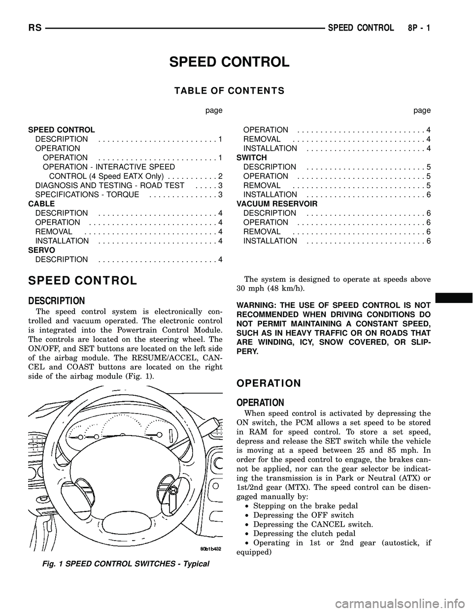
The controls are located on the steering wheel. The
ON/OFF, and SET buttons are located on the left side
of the airbag module. The RESUME/ACCEL, CAN-
CEL and COAST buttons are located on the right
side of the airbag module (Fig. 1).The system is designed to operate at speeds above
30 mph (48 km/h).
WARNING: THE USE OF SPEED CONTROL IS NOT
RECOMMENDED WHEN DRIVING CONDITIONS DO
NOT PERMIT MAINTAINING A CONSTANT SPEED,
SUCH AS IN HEAVY TRAFFIC OR ON ROADS THAT
ARE WINDING, ICY, SNOW COVERED, OR SLIP-
PERY.
OPERATION
OPERATION
When speed control is activated by depressing the
ON switch, the PCM allows a set speed to be stored
in RAM for speed control. To store a set speed,
depress and release the SET switch while the vehicle
is moving at a speed between 25 and 85 mph. In
order for the speed control to engage, the brakes can-
not be applied, nor can the gear selector be indicat-
ing the transmission is in Park or Neutral (ATX) or
1st/2nd gear (MTX). The speed control can be disen-
gaged manually by:
²Stepping on the brake pedal
²Depressing the OFF switch
²Depressing the CANCEL switch.
²Depressing the clutch pedal
²Operating in 1st or 2nd gear (autostick, if
equipped)
Fig. 1 SPEED CONTROL SWITCHES - Typical
RSSPEED CONTROL8P-1
Page 536 of 2339
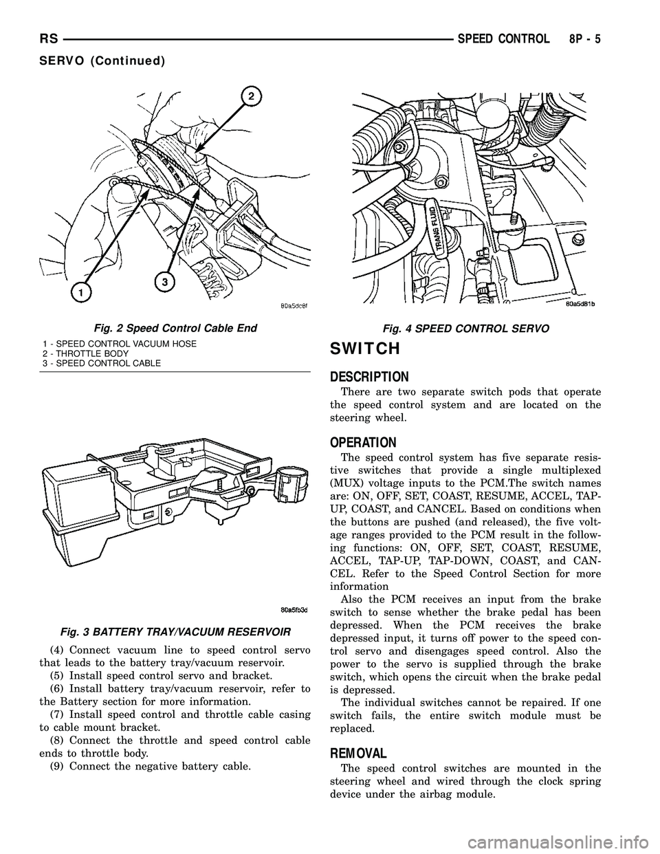
(4) Connect vacuum line to speed control servo
that leads to the battery tray/vacuum reservoir.
(5) Install speed control servo and bracket.
(6) Install battery tray/vacuum reservoir, refer to
the Battery section for more information.
(7) Install speed control and throttle cable casing
to cable mount bracket.
(8) Connect the throttle and speed control cable
ends to throttle body.
(9) Connect the negative battery cable.
SWITCH
DESCRIPTION
There are two separate switch pods that operate
the speed control system and are located on the
steering wheel.
OPERATION
The speed control system has five separate resis-
tive switches that provide a single multiplexed
(MUX) voltage inputs to the PCM.The switch names
are: ON, OFF, SET, COAST, RESUME, ACCEL, TAP-
UP, COAST, and CANCEL. Based on conditions when
the buttons are pushed (and released), the five volt-
age ranges provided to the PCM result in the follow-
ing functions: ON, OFF, SET, COAST, RESUME,
ACCEL, TAP-UP, TAP-DOWN, COAST, and CAN-
CEL. Refer to the Speed Control Section for more
information
Also the PCM receives an input from the brake
switch to sense whether the brake pedal has been
depressed. When the PCM receives the brake
depressed input, it turns off power to the speed con-
trol servo and disengages speed control. Also the
power to the servo is supplied through the brake
switch, which opens the circuit when the brake pedal
is depressed.
The individual switches cannot be repaired. If one
switch fails, the entire switch module must be
replaced.
REMOVAL
The speed control switches are mounted in the
steering wheel and wired through the clock spring
device under the airbag module.
Fig. 2 Speed Control Cable End
1 - SPEED CONTROL VACUUM HOSE
2 - THROTTLE BODY
3 - SPEED CONTROL CABLE
Fig. 3 BATTERY TRAY/VACUUM RESERVOIR
Fig. 4 SPEED CONTROL SERVO
RSSPEED CONTROL8P-5
SERVO (Continued)
Page 560 of 2339
NAVIGATION/TELECOMMUNICATION
TABLE OF CONTENTS
page page
NAVIGATION/TELECOMMUNICATION
DESCRIPTION..........................1
OPERATION............................1
DIAGNOSIS AND TESTING
TELECOMMUNICATION.................1HANDS FREE MODULE
REMOVAL.............................3
INSTALLATION..........................3
NAVIGATION/
TELECOMMUNICATION
DESCRIPTION
TELECOMMUNICATIONS
A hands-free cellular system is an available option
on this vehicle. It uses BluetoothŸ technology to pro-
vide wireless communication between the operator's
compatible cellular telephone and the vehicle's
on-board receiver.
The system uses voice recognition technology to
control operation. The incoming voice is broadcast
through the vehicle's radio speakers, automatically
overriding any other audio signals on the speakers
when the hands-free system is in use. A microphone
in the rearview mirror picks up vehicle occupant's
voices. If a call is in progress when the ignition is
switched off, the hands-free system will continue to
operate for up to 45 seconds as part of the Accessory
Relay Delay function. Thereafter, the call can con-
tinue on the hand-held telephone.
The center console front storage compartment
includes a cellular telephone holder, but the system
will communicate with a telephone that is anywhere
within the vehicle. However, covering the hand held
phone or the hands-free phone module with a metal
object may block the signal. The system will recog-
nize up to seven telephones, each of which is given a
spoken identification by the user during the setup
process. The system includes Spanish voice recogni-
tion in addition to English.
Two buttons on the rearview mirror, identified with
ISO icons, control the system: A9phone9button turns
the system on and off; a9voice recognition9(or voice
command) button prompts the hands-free system to
listen for a voice command.
OPERATION
TELECOMMUNICATION
Two buttons on the rearview mirror, identified with
ISO icons, control the system: A9phone9button turns
the system on and off; a9voice recognition9(or voice
command) button prompts the hands-free system to
listen for a voice command. The system includes the
following features:
²Phonebook - Stores telephone numbers for later
recall by name or other verbal identification, called a
voice tag, and memory location.
²Four memory locations - Home, Work, Mobile
and Pager. A maximum of 32 unique names or voice
tags may be stored at the same time, with a different
number in each of the four memory locations.
²Voice tag dialing - Dials the number associated
with a voice tag and memory location.
²Digit dialing - Dials the telephone number by
recognizing the names of the digits as they are spo-
ken.
²Receiving calls - A voice prompt notifies the user
of an incoming call. Pressing the ªphoneº button
answers the call.
²Privacy Mode - Switches the call to the hand-
held telephone and the hands-free system and back
again using the ªvoice recognitionº (or ªvoice com-
mandº) button and a voice command, if desired.
DIAGNOSIS AND TESTING
TELECOMMUNICATION
Any diagnosis of the Telecommunication sys-
tem should begin with the use of the DRB IIIt
diagnostic tool. For information on the use of
the DRB IIIt, refer to the appropriate Diagnos-
tic Service Information.
For complete circuit diagrams, refer to the appro-
priate wiring information.
RSNAVIGATION/TELECOMMUNICATION8T-1
Page 2157 of 2339
defogger function will be active for 10 minutes and
can be turned off by a switch press. The defogger will
function while the control is in the ON mode.
²FAN/MODE± The Fan and Mode knobs have
17 manual selectable positions. Manually changing
either of the rotary knobs for mode or fan speed set-
tings makes control of that blower motor manual. If
only one is changed manually, the other remains
under automatic control. Pressing the HI-AUTO/LO-
AUTO rocker switch restores full automatic control.
²BLOWER DELAY TIMER± The word DELAY
is displayed at start-up to signify that the system is
waiting so that cold air will not be blowing. This tells
the operator that it is unnecessary to turn the sys-
tem off, raise the temperature setting or turn the fan
speed setting down to prevent cold air from blowing.
A countdown in minutes and seconds until the engine
is warm enough to begin delivering heat to the pas-
sengers alternates with the DELAY message at 25
second intervals. This countdown is based on actual
measurement of the rate of engine coolant tempera-
ture change. During the delay time, mix mode is
selected and the fan operates at a low speed to keep
the windshield fog free.
²REAR CONTROL (Three-Zone only)± When
the Rear System control knob is moved to the OFF
position, there will be a delay of approximately 1 sec-
ond before the system actually turns off. This delay
is to prevent an undesired blower dropout if the knob
is moved through OFF to the other selections.
REAR CONTROL PANEL ± THREE ZONE ATC
SYSTEM
Primary control of the rear compartment heating-
A/C system for the Three-Zone ATC system is in the
instrument panel center stack. This control allows
the driver to turn the rear heating-A/C system off, or
allows the intermediate seat occupants control of the
rear system by switching to the REAR position, or
provides fully automatic control based on the temper-
ature setting shown on the front control display.
²REAR CONTROL± Selecting automatic control
of the rear unit at the instrument panel, illuminates
a Locked Padlock in the rear control panel display.
Selecting REAR activates the rear control panel and
the Padlock then appears unlocked.
²FAN KNOB± The rear fan control has Off and
AUTO positions and a range of manual speed set-
tings that override the AUTO setting.
²MODE KNOB± The mode control allows inter-
mediate seat occupants to manually override the
automatic mode and select any balance of air flow
between overhead and floor outlets from full over-
head to full floor.
²SET TEMP± The rear set temp control will
operate identical to the front controls. If the frontcontrol rear set temp button is pressed simulta-
neously with the rear control head, then the front
control head press events shall have priority, i.e. if
the front user presses Rear Set Temp down and the
rear user presses Set Temp up, then the rear set
temp will decrease.
DIAGNOSIS AND TESTING
A/C COOL DOWN TEST
The heater-A/C control module can perform an A/C
cool down test, which is a test performed during the
manufacturing process to confirm that the air condi-
tioning system is performing satisfactorily. This test
can also provide a quick confirmation of air condi-
tioning system performance to the service technician.
If the test is completed satisfactorily, no further ser-
vice is required. If the test is failed, proceed to the
A/C Performance Test to confirm the A/C system is
operating properly, or use a DRBIIItscan tool to
diagnose the A/C system control and distribution sys-
tems. Refer to the appropriate diagnostic informa-
tion.
MANUAL TEMPERATURE CONTROL
The front blower speed and rear blower speed (if
equipped with rear HVAC) must be set to High and
the evaporator temperature sensor must be greater
than 13É C (55É F) or the test will fail immediately.
The test is activated by depressing the A/C and Rear
Wipe/Wash buttons simultaneously and holding them
depressed for no less than five seconds. The Rear
Wipe/Wash and A/C LEDs will blink on and off until
the test is complete. If the LEDs stop blinking before
two minutes, then the cool down test has been com-
pleted successfully. If the two minutes expire without
the expansion valve temperature reaching -6É C (20É
F) less than the outside air temperature, then the
cool down test has been failed and further A/C sys-
tem diagnosis is required. If the test is failed, the
LEDs will continue to blink until the vehicle has
been driven for greater than 13 km (8 miles).
AUTOMATIC TEMPERATURE CONTROL
The ambient air temperature in the room where
the vehicle will be tested must be a minimum of 21É
C (70ÉF) for this test. The test is activated by
depressing the A/C and PWR buttons simultaneously
and holding them depressed for no less than four sec-
onds. The snowflake icon and the DELAY text in the
ATC display will blink on and off alternately until
the test is complete. If the snowflake icon and the
DELAY text stop blinking before two minutes, then
the cool down test has been completed successfully. If
the two minutes expire without the evaporator tem-
perature reaching -6É C (20É F) less than the evapo-
24 - 6 HEATING & AIR CONDITIONINGRS
HEATING & AIR CONDITIONING (Continued)
Page 2170 of 2339
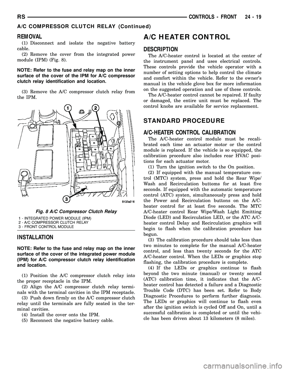
REMOVAL
(1) Disconnect and isolate the negative battery
cable.
(2) Remove the cover from the integrated power
module (IPM) (Fig. 8).
NOTE: Refer to the fuse and relay map on the inner
surface of the cover of the IPM for A/C compressor
clutch relay identification and location.
(3) Remove the A/C compressor clutch relay from
the IPM.
INSTALLATION
NOTE: Refer to the fuse and relay map on the inner
surface of the cover of the integrated power module
(IPM) for A/C compressor clutch relay identification
and location.
(1) Position the A/C compressor clutch relay into
the proper receptacle in the IPM.
(2) Align the A/C compressor clutch relay termi-
nals with the terminal cavities in the IPM receptacle.
(3) Push down firmly on the A/C compressor clutch
relay until the terminals are fully seated in the ter-
minal cavities.
(4) Install the cover onto the IPM.
(5) Reconnect the negative battery cable.
A/C HEATER CONTROL
DESCRIPTION
The A/C-heater control is located at the center of
the instrument panel and uses electrical controls.
These controls provide the vehicle operator with a
number of setting options to help control the climate
and comfort within the vehicle. Refer to the owner's
manual in the vehicle glove box for more information
on the suggested operation and use of these controls.
The A/C-heater control cannot be repaired. If faulty
or damaged, the entire unit must be replaced. The
control knobs are available for service replacement.
STANDARD PROCEDURE
A/C-HEATER CONTROL CALIBRATION
The A/C-heater control module must be recali-
brated each time an actuator motor or the control
module is replaced. If the vehicle is so equipped, the
calibration procedure also includes rear HVAC posi-
tions for each actuator motor.
(1) Turn the ignition switch to the On position.
(2) If equipped with the manual temperature con-
trol (MTC) system, press and hold the Rear Wipe/
Wash and Recirculation buttoms for at least five
seconds. If equipped with the automatic temperature
control (ATC) systen, simultaneously press and hold
the Power and Recirculation buttons on the A/C-
heater control for at least five seconds. The MTC
A/C-heater control Rear Wipe/Wash Light Emitting
Diode (LED) and Recirculation LED, or the ATC A/C-
heater control Delay and Recirculation graphics will
begin to flash when the calibration procedure has
begun.
(3) The calibration procedure should take less than
two minutes to complete for the manual A/C-heater
control, and less than twenty seconds for the ATC
A/C-heater control. When the LEDs or graphics stop
flashing, the calibration procedure is complete.
(4) If the LEDs or graphics continue to flash
beyond the two minute (manual) or twenty second
(ATC) calibration time, it indicates that the A/C-
heater control has detected a failure and a Diagnostic
Trouble Code (DTC) has been set. Refer to Body
Diagnostic Procedures to perform further diagnosis.
The LEDs or graphics will continue to flash even
after the ignition switch is cycled Off and On, until a
successful calibration is completed or until the vehi-
cle has been driven about 13 kilometers (8 miles).
Fig. 8 A/C Compressor Clutch Relay
1 - INTEGRATED POWER MODULE (IPM)
2 - A/C COMPRESSOR CLUTCH RELAY
3 - FRONT CONTROL MODULE
RSCONTROLS - FRONT24-19
A/C COMPRESSOR CLUTCH RELAY (Continued)