exhaust CHRYSLER VOYAGER 2005 Service Manual
[x] Cancel search | Manufacturer: CHRYSLER, Model Year: 2005, Model line: VOYAGER, Model: CHRYSLER VOYAGER 2005Pages: 2339, PDF Size: 59.69 MB
Page 1 of 2339
GROUP TAB LOCATOR
Introduction
0Lubrication & Maintenance
2Suspension
3Differential & Driveline
5Brakes
7Cooling
8AAudio
8BChime/Buzzer
8EElectronic Control Modules
8FEngine Systems
8GHeated Systems
8HHorn
8IIgnition Control
8JInstrument Cluster
8LLamps
8MMessage Systems
8NPower Systems
8ORestraints
8PSpeed Control
8QVehicle Theft Security
8RWipers/Washers
8TNavigation/Telecommunication
8WWiring
9Engine
11Exhaust System
13Frame & Bumpers
14Fuel System
19Steering
21Transmission/Transaxle
22Tires/Wheels
23Body
24Heating & Air Conditioning
25Emissions Control
Component and System Index
Service Manual Comment Forms (Rear of Manual)
Page 16 of 2339
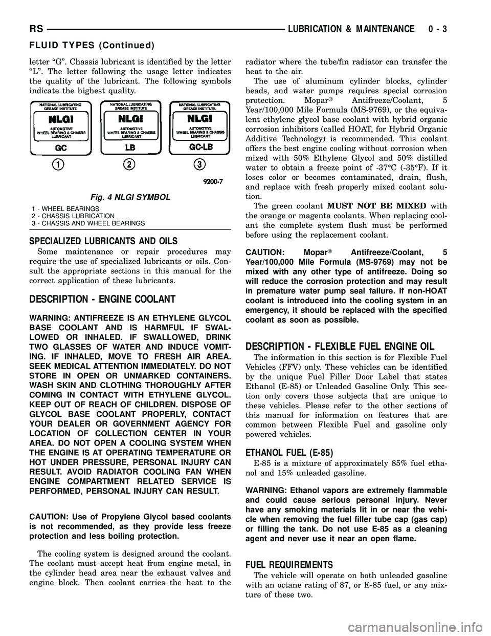
letter ªGº. Chassis lubricant is identified by the letter
ªLº. The letter following the usage letter indicates
the quality of the lubricant. The following symbols
indicate the highest quality.
SPECIALIZED LUBRICANTS AND OILS
Some maintenance or repair procedures may
require the use of specialized lubricants or oils. Con-
sult the appropriate sections in this manual for the
correct application of these lubricants.
DESCRIPTION - ENGINE COOLANT
WARNING: ANTIFREEZE IS AN ETHYLENE GLYCOL
BASE COOLANT AND IS HARMFUL IF SWAL-
LOWED OR INHALED. IF SWALLOWED, DRINK
TWO GLASSES OF WATER AND INDUCE VOMIT-
ING. IF INHALED, MOVE TO FRESH AIR AREA.
SEEK MEDICAL ATTENTION IMMEDIATELY. DO NOT
STORE IN OPEN OR UNMARKED CONTAINERS.
WASH SKIN AND CLOTHING THOROUGHLY AFTER
COMING IN CONTACT WITH ETHYLENE GLYCOL.
KEEP OUT OF REACH OF CHILDREN. DISPOSE OF
GLYCOL BASE COOLANT PROPERLY, CONTACT
YOUR DEALER OR GOVERNMENT AGENCY FOR
LOCATION OF COLLECTION CENTER IN YOUR
AREA. DO NOT OPEN A COOLING SYSTEM WHEN
THE ENGINE IS AT OPERATING TEMPERATURE OR
HOT UNDER PRESSURE, PERSONAL INJURY CAN
RESULT. AVOID RADIATOR COOLING FAN WHEN
ENGINE COMPARTMENT RELATED SERVICE IS
PERFORMED, PERSONAL INJURY CAN RESULT.
CAUTION: Use of Propylene Glycol based coolants
is not recommended, as they provide less freeze
protection and less boiling protection.
The cooling system is designed around the coolant.
The coolant must accept heat from engine metal, in
the cylinder head area near the exhaust valves and
engine block. Then coolant carries the heat to theradiator where the tube/fin radiator can transfer the
heat to the air.
The use of aluminum cylinder blocks, cylinder
heads, and water pumps requires special corrosion
protection. MopartAntifreeze/Coolant, 5
Year/100,000 Mile Formula (MS-9769), or the equiva-
lent ethylene glycol base coolant with hybrid organic
corrosion inhibitors (called HOAT, for Hybrid Organic
Additive Technology) is recommended. This coolant
offers the best engine cooling without corrosion when
mixed with 50% Ethylene Glycol and 50% distilled
water to obtain a freeze point of -37ÉC (-35ÉF). If it
loses color or becomes contaminated, drain, flush,
and replace with fresh properly mixed coolant solu-
tion.
The green coolantMUST NOT BE MIXEDwith
the orange or magenta coolants. When replacing cool-
ant the complete system flush must be performed
before using the replacement coolant.
CAUTION: MoparTAntifreeze/Coolant, 5
Year/100,000 Mile Formula (MS-9769) may not be
mixed with any other type of antifreeze. Doing so
will reduce the corrosion protection and may result
in premature water pump seal failure. If non-HOAT
coolant is introduced into the cooling system in an
emergency, it should be replaced with the specified
coolant as soon as possible.
DESCRIPTION - FLEXIBLE FUEL ENGINE OIL
The information in this section is for Flexible Fuel
Vehicles (FFV) only. These vehicles can be identified
by the unique Fuel Filler Door Label that states
Ethanol (E-85) or Unleaded Gasoline Only. This sec-
tion only covers those subjects that are unique to
these vehicles. Please refer to the other sections of
this manual for information on features that are
common between Flexible Fuel and gasoline only
powered vehicles.
ETHANOL FUEL (E-85)
E-85 is a mixture of approximately 85% fuel etha-
nol and 15% unleaded gasoline.
WARNING: Ethanol vapors are extremely flammable
and could cause serious personal injury. Never
have any smoking materials lit in or near the vehi-
cle when removing the fuel filler tube cap (gas cap)
or filling the tank. Do not use E-85 as a cleaning
agent and never use it near an open flame.
FUEL REQUIREMENTS
The vehicle will operate on both unleaded gasoline
with an octane rating of 87, or E-85 fuel, or any mix-
ture of these two.
Fig. 4 NLGI SYMBOL
1 - WHEEL BEARINGS
2 - CHASSIS LUBRICATION
3 - CHASSIS AND WHEEL BEARINGS
RSLUBRICATION & MAINTENANCE0-3
FLUID TYPES (Continued)
Page 20 of 2339
FLUID FILL/CHECK
LOCATIONS
DESCRIPTION
The fluid check/fill point locations are located in
each applicable service manual section.
LUBRICATION POINTS
DESCRIPTION
Lubrication point locations are located in each
applicable Sections.
MAINTENANCE SCHEDULES
DESCRIPTION
DESCRIPTION
There are two maintenance schedules that show
therequiredservice for your vehicle.
First is ScheduleªBº. It is for vehicles that are
operated under the conditions that are listed below
and at the beginning of the schedule.
²Day or night temperatures are below 32É F (0É
C).
²Stop and go driving.
²Extensive engine idling.
²Driving in dusty conditions.
²Short trips of less than 10 miles (16 km).
²More than 50% of your driving is at sustained
high speeds during hot weather, above 90É F (32É C).
²Trailer towing.L
²Taxi, police, or delivery service (commercial ser-
vice).L
²Off-road or desert operation.
NOTE: Most vehicles are operated under the condi-
tions listed for Schedule(B(.
Second is ScheduleªAº. It is for vehicles that are
not operated under any of the conditions listed under
Schedule9B9.
Use the schedule that best describes your driving
conditions. Where time and mileage are listed, follow
the interval that occurs first.
CAUTION: Failure to perform the required mainte-
nance items may result in damage to the vehicle.
At Each Stop for Fuel
²Check the engine oil level about 5 minutes after
a fully warmed engine is shut off. Checking the oil
level while the vehicle is on level ground will
improve the accuracy of the oil level reading. Add oil
only when the level is at or below the ADD or MIN
mark.
²Check the windshield washer solvent and add if
required.
Once a Month
²Check tire pressure and look for unusual wear
or damage.
²Inspect the battery and clean and tighten the
terminals as required.
²Check the fluid levels of coolant reservoir, brake
master cylinder and transmission, add as needed.
²Check all lights and all other electrical items for
correct operation.
At Each Oil Change
²Change the engine oil filter.
²Inspect the exhaust system.
²Inspect the brake hoses.
²Inspect the CV joints and front suspension com-
ponents.
²Check the automatic transmission fluid level.
²Check the coolant level, hoses, and clamps.
SCHEDULE B
Follow schedule ªBº if you usually operate your
vehicle under one or more of the following conditions.
Change the automatic transmission fluid and filter
every 60,000 miles (96 000 km) if the vehicle is usu-
ally operated under one or more of the conditions
marked with anL.
²Day or night temperatures are below 32É F (0É
C).
²Stop and go driving.
²Extensive engine idling.
²Driving in dusty conditions.
²Short trips of less than 10 miles (16 km).
²More than 50% of your driving is at sustained
high speeds during hot weather, above 90É F (32É C).
²Trailer towing.L
²Taxi, police, or delivery service (commercial ser-
vice).L
²Off-road or desert operation.
RSLUBRICATION & MAINTENANCE0-7
Page 26 of 2339
DESCRIPTION - EXPORT
There are two maintenance schedules that show
therequiredservice for your vehicle.
First is ScheduleªAº. It is for vehicles that are not
operated under any of the conditions listed under
Schedule9B9.
Second is ScheduleªBº. It is for vehicles that are
operated under the conditions that are listed below
and at the beginning of the schedule.
²Day or night temperatures are below 0É C (32É
F).
²Stop and go driving.
²Extensive engine idling.
²Driving in dusty conditions.
²Short trips of less than 16 km (10 miles).
²More than 50% of your driving is at sustained
high speeds during hot weather, above 32É C (90É F).
²Trailer towing.L
²Taxi, police, or delivery service (commercial ser-
vice).L
²Off-road or desert operation.
NOTE: Most vehicles are operated under the condi-
tions listed for Schedule(B(.
Use the schedule that best describes your driving
conditions. Where time and mileage are listed, follow
the interval that occurs first.
CAUTION: Failure to perform the required mainte-
nance items may result in damage to the vehicle.
At Each Stop for Fuel
²Check the engine oil level about 5 minutes after
a fully warmed engine is shut off. Checking the oil
level while the vehicle is on level ground will
improve the accuracy of the oil level reading. Add oil
only when the level is at or below the ADD or MIN
mark.
²Check the windshield washer solvent and add if
required.
Once a Month
²Check tire pressure and look for unusual wear
or damage.
²Inspect the battery and clean and tighten the
terminals as required.
²Check the fluid levels of coolant reservoir, brake
master cylinder and transmission, add as needed.
²Check all lights and all other electrical items for
correct operation.
At Each Oil Change
²Change the engine oil filter.
²Inspect the exhaust system.
²Inspect the brake hoses.
²Inspect the CV joints and front suspension com-
ponents.
²Check the automatic transmission fluid level.
²Check the manual transmission fluid level.
²Check the coolant level, hoses, and clamps.
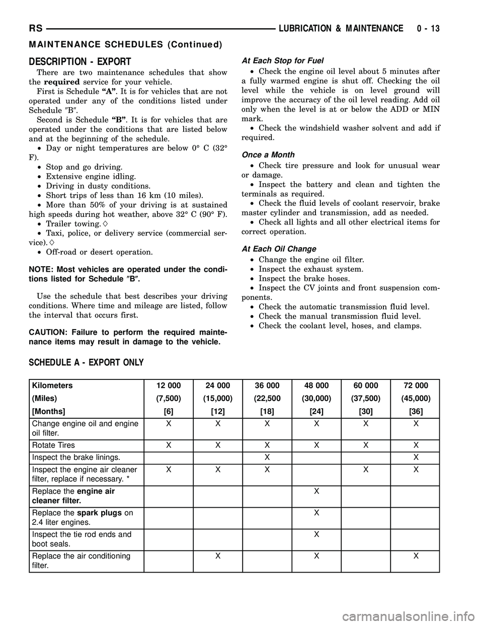
SCHEDULE A - EXPORT ONLY
Kilometers 12 000 24 000 36 000 48 000 60 000 72 000
(Miles) (7,500) (15,000) (22,500 (30,000) (37,500) (45,000)
[Months] [6] [12] [18] [24] [30] [36]
Change engine oil and engine
oil filter.XXXXX X
Rotate Tires XXXXX X
Inspect the brake linings. X X
Inspect the engine air cleaner
filter, replace if necessary. *XXX X X
Replace theengine air
cleaner filter.X
Replace thespark plugson
2.4 liter engines.X
Inspect the tie rod ends and
boot seals.X
Replace the air conditioning
filter.XX X
RSLUBRICATION & MAINTENANCE0-13
MAINTENANCE SCHEDULES (Continued)
Page 35 of 2339
At Each Oil Change
²Change the engine oil filter.
²Inspect the exhaust system.
²Inspect the brake hoses.
²Inspect the CV joints and front suspension com-
ponents.²Check the manual transmission fluid level.
²Check the coolant level, hoses, and clamps.
²Inspect engine accessory drive belts. Replace as
necessary.
²Inspect for the presence of water in the fuel fil-
ter/water separator unit.
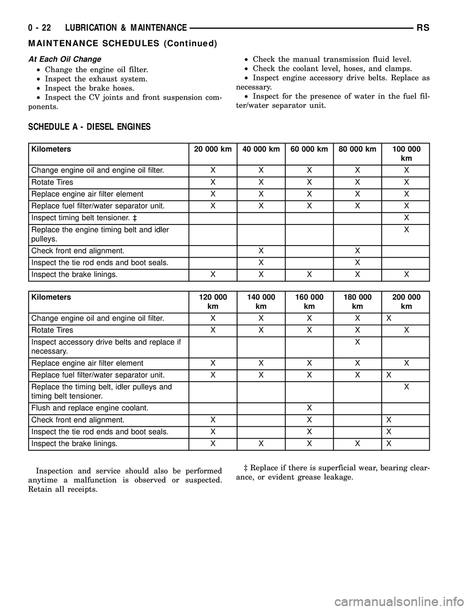
SCHEDULE A - DIESEL ENGINES
Kilometers 20 000 km 40 000 km 60 000 km 80 000 km 100 000
km
Change engine oil and engine oil filter.XXXX X
Rotate TiresXXXX X
Replace engine air filter elementXXXX X
Replace fuel filter/water separator unit.XXXX X
Inspect timing belt tensioner. ³X
Replace the engine timing belt and idler
pulleys.X
Check front end alignment. X X
Inspect the tie rod ends and boot seals. X X
Inspect the brake linings.XXXX X
Kilometers 120 000
km140 000
km160 000
km180 000
km200 000
km
Change engine oil and engine oil filter.XXXXX
Rotate TiresXXXX X
Inspect accessory drive belts and replace if
necessary.X
Replace engine air filter elementXXXX X
Replace fuel filter/water separator unit.XXXXX
Replace the timing belt, idler pulleys and
timing belt tensioner.X
Flush and replace engine coolant. X
Check front end alignment. X X X
Inspect the tie rod ends and boot seals. X X X
Inspect the brake linings.XXXXX
Inspection and service should also be performed
anytime a malfunction is observed or suspected.
Retain all receipts.³ Replace if there is superficial wear, bearing clear-
ance, or evident grease leakage.
0 - 22 LUBRICATION & MAINTENANCERS
MAINTENANCE SCHEDULES (Continued)
Page 39 of 2339
CAUTION: Do not crank starter motor on disabled
vehicle for more than 15 seconds, starter may over-
heat and could fail.
(7) If engine does not start within 15 seconds, stop
cranking engine and allow starter to cool (15 min-
utes), before cranking again.
DISCONNECT CABLE CLAMPS AS FOLLOWS:
²Disconnect BLACK cable clamp from engine
ground on disabled vehicle.
²When using a Booster vehicle, disconnect
BLACK cable clamp from battery negative terminal.
Disconnect RED cable clamp from battery positive
terminal.
²Disconnect RED cable clamp from battery posi-
tive terminal on disabled vehicle.
TOWING
STANDARD PROCEDURE - TOWING
WARNINGS AND CAUTIONS
WARNING: DO NOT ALLOW TOWING ATTACHMENT
DEVICES TO CONTACT THE FUEL TANK OR LINES,
FUEL LEAK CAN RESULT.
DO NOT LIFT OR TOW VEHICLE BY FRONT OR
REAR BUMPER.
DO NOT GO UNDER A LIFTED VEHICLE IF NOT
SUPPORTED PROPERLY ON SAFETY STANDS.
DO NOT ALLOW PASSENGERS TO RIDE IN A
TOWED VEHICLE.USE A SAFETY CHAIN THAT IS INDEPENDENT
FROM THE TOWING ATTACHMENT DEVICE.
CAUTION: Do not damage brake lines, exhaust sys-
tem, shock absorbers, sway bars, or any other
under vehicle components when attaching towing
device to vehicle.
Do not secure vehicle to towing device by the use
of front or rear suspension or steering components.
Remove or secure loose or protruding objects from
a damaged vehicle before towing.
Refer to state and local rules and regulations before
towing a vehicle.
Do not allow weight of towed vehicle to bear on
lower fascia, air dams, or spoilers.
RECOMMENDED TOWING EQUIPMENT
To avoid damage to bumper fascia and air dams
use:
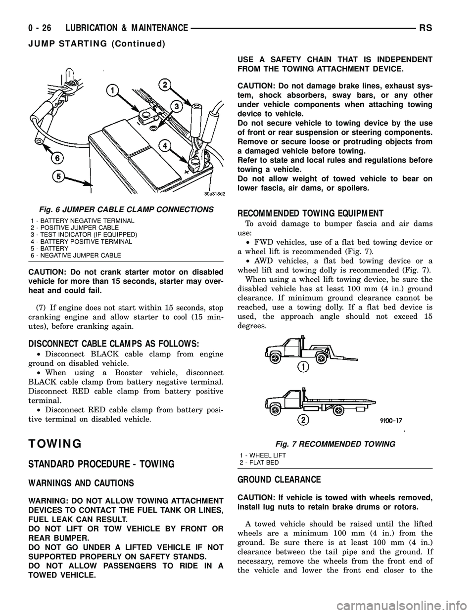
²FWD vehicles, use of a flat bed towing device or
a wheel lift is recommended (Fig. 7).
²AWD vehicles, a flat bed towing device or a
wheel lift and towing dolly is recommended (Fig. 7).
When using a wheel lift towing device, be sure the
disabled vehicle has at least 100 mm (4 in.) ground
clearance. If minimum ground clearance cannot be
reached, use a towing dolly. If a flat bed device is
used, the approach angle should not exceed 15
degrees.
GROUND CLEARANCE
CAUTION: If vehicle is towed with wheels removed,
install lug nuts to retain brake drums or rotors.
A towed vehicle should be raised until the lifted
wheels are a minimum 100 mm (4 in.) from the
ground. Be sure there is at least 100 mm (4 in.)
clearance between the tail pipe and the ground. If
necessary, remove the wheels from the front end of
the vehicle and lower the front end closer to the
Fig. 6 JUMPER CABLE CLAMP CONNECTIONS
1 - BATTERY NEGATIVE TERMINAL
2 - POSITIVE JUMPER CABLE
3 - TEST INDICATOR (IF EQUIPPED)
4 - BATTERY POSITIVE TERMINAL
5 - BATTERY
6 - NEGATIVE JUMPER CABLE
Fig. 7 RECOMMENDED TOWING
1 - WHEEL LIFT
2 - FLAT BED
0 - 26 LUBRICATION & MAINTENANCERS
JUMP STARTING (Continued)
Page 238 of 2339
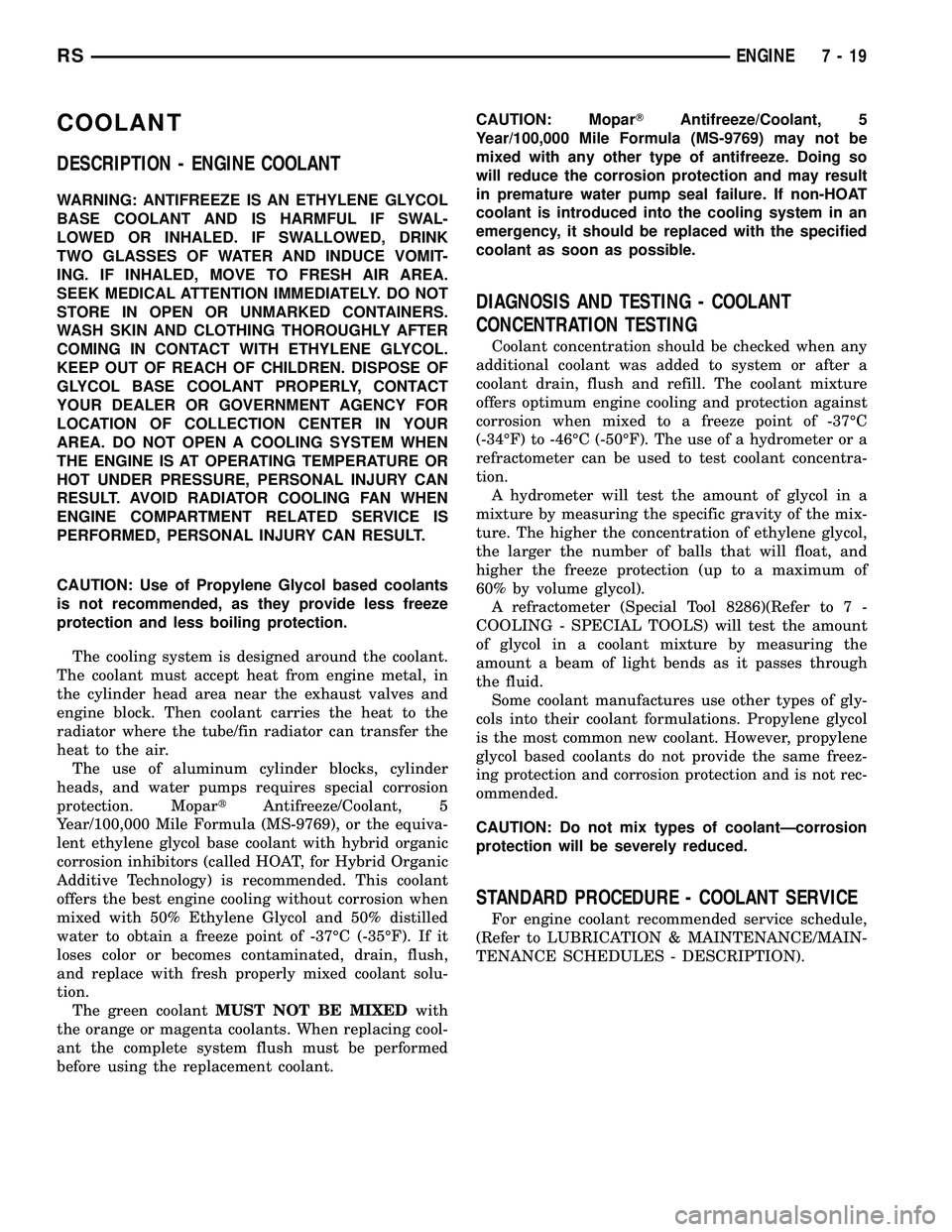
COOLANT
DESCRIPTION - ENGINE COOLANT
WARNING: ANTIFREEZE IS AN ETHYLENE GLYCOL
BASE COOLANT AND IS HARMFUL IF SWAL-
LOWED OR INHALED. IF SWALLOWED, DRINK
TWO GLASSES OF WATER AND INDUCE VOMIT-
ING. IF INHALED, MOVE TO FRESH AIR AREA.
SEEK MEDICAL ATTENTION IMMEDIATELY. DO NOT
STORE IN OPEN OR UNMARKED CONTAINERS.
WASH SKIN AND CLOTHING THOROUGHLY AFTER
COMING IN CONTACT WITH ETHYLENE GLYCOL.
KEEP OUT OF REACH OF CHILDREN. DISPOSE OF
GLYCOL BASE COOLANT PROPERLY, CONTACT
YOUR DEALER OR GOVERNMENT AGENCY FOR
LOCATION OF COLLECTION CENTER IN YOUR
AREA. DO NOT OPEN A COOLING SYSTEM WHEN
THE ENGINE IS AT OPERATING TEMPERATURE OR
HOT UNDER PRESSURE, PERSONAL INJURY CAN
RESULT. AVOID RADIATOR COOLING FAN WHEN
ENGINE COMPARTMENT RELATED SERVICE IS
PERFORMED, PERSONAL INJURY CAN RESULT.
CAUTION: Use of Propylene Glycol based coolants
is not recommended, as they provide less freeze
protection and less boiling protection.
The cooling system is designed around the coolant.
The coolant must accept heat from engine metal, in
the cylinder head area near the exhaust valves and
engine block. Then coolant carries the heat to the
radiator where the tube/fin radiator can transfer the
heat to the air.
The use of aluminum cylinder blocks, cylinder
heads, and water pumps requires special corrosion
protection. MopartAntifreeze/Coolant, 5
Year/100,000 Mile Formula (MS-9769), or the equiva-
lent ethylene glycol base coolant with hybrid organic
corrosion inhibitors (called HOAT, for Hybrid Organic
Additive Technology) is recommended. This coolant
offers the best engine cooling without corrosion when
mixed with 50% Ethylene Glycol and 50% distilled
water to obtain a freeze point of -37ÉC (-35ÉF). If it
loses color or becomes contaminated, drain, flush,
and replace with fresh properly mixed coolant solu-
tion.
The green coolantMUST NOT BE MIXEDwith
the orange or magenta coolants. When replacing cool-
ant the complete system flush must be performed
before using the replacement coolant.CAUTION: MoparTAntifreeze/Coolant, 5
Year/100,000 Mile Formula (MS-9769) may not be
mixed with any other type of antifreeze. Doing so
will reduce the corrosion protection and may result
in premature water pump seal failure. If non-HOAT
coolant is introduced into the cooling system in an
emergency, it should be replaced with the specified
coolant as soon as possible.
DIAGNOSIS AND TESTING - COOLANT
CONCENTRATION TESTING
Coolant concentration should be checked when any
additional coolant was added to system or after a
coolant drain, flush and refill. The coolant mixture
offers optimum engine cooling and protection against
corrosion when mixed to a freeze point of -37ÉC
(-34ÉF) to -46ÉC (-50ÉF). The use of a hydrometer or a
refractometer can be used to test coolant concentra-
tion.
A hydrometer will test the amount of glycol in a
mixture by measuring the specific gravity of the mix-
ture. The higher the concentration of ethylene glycol,
the larger the number of balls that will float, and
higher the freeze protection (up to a maximum of
60% by volume glycol).
A refractometer (Special Tool 8286)(Refer to 7 -
COOLING - SPECIAL TOOLS) will test the amount
of glycol in a coolant mixture by measuring the
amount a beam of light bends as it passes through
the fluid.
Some coolant manufactures use other types of gly-
cols into their coolant formulations. Propylene glycol
is the most common new coolant. However, propylene
glycol based coolants do not provide the same freez-
ing protection and corrosion protection and is not rec-
ommended.
CAUTION: Do not mix types of coolantÐcorrosion
protection will be severely reduced.
STANDARD PROCEDURE - COOLANT SERVICE
For engine coolant recommended service schedule,
(Refer to LUBRICATION & MAINTENANCE/MAIN-
TENANCE SCHEDULES - DESCRIPTION).
RSENGINE7-19
Page 297 of 2339
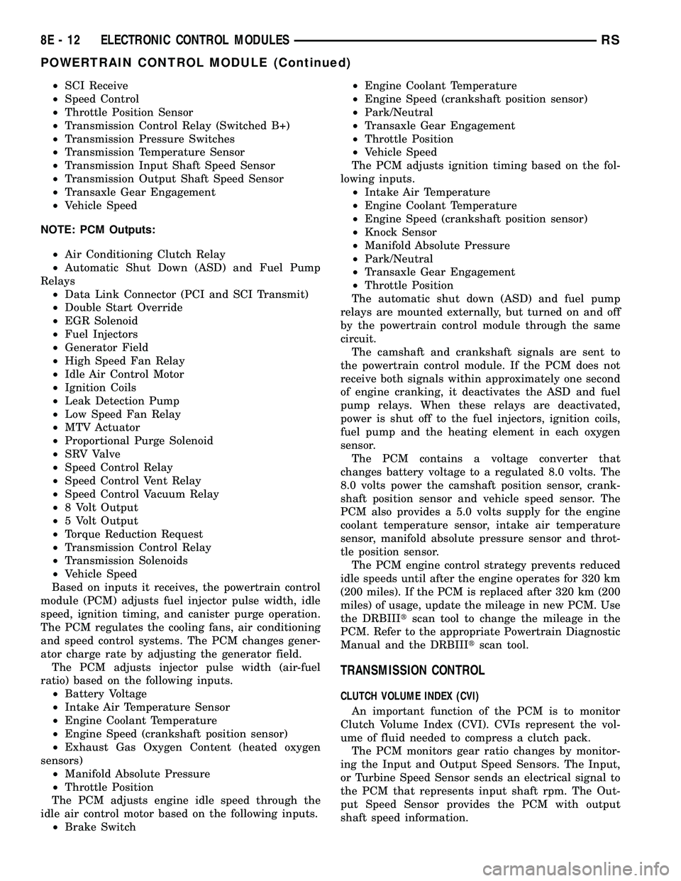
²SCI Receive
²Speed Control
²Throttle Position Sensor
²Transmission Control Relay (Switched B+)
²Transmission Pressure Switches
²Transmission Temperature Sensor
²Transmission Input Shaft Speed Sensor
²Transmission Output Shaft Speed Sensor
²Transaxle Gear Engagement
²Vehicle Speed
NOTE: PCM Outputs:
²Air Conditioning Clutch Relay
²Automatic Shut Down (ASD) and Fuel Pump
Relays
²Data Link Connector (PCI and SCI Transmit)
²Double Start Override
²EGR Solenoid
²Fuel Injectors
²Generator Field
²High Speed Fan Relay
²Idle Air Control Motor
²Ignition Coils
²Leak Detection Pump
²Low Speed Fan Relay
²MTV Actuator
²Proportional Purge Solenoid
²SRV Valve
²Speed Control Relay
²Speed Control Vent Relay
²Speed Control Vacuum Relay
²8 Volt Output
²5 Volt Output
²Torque Reduction Request
²Transmission Control Relay
²Transmission Solenoids
²Vehicle Speed
Based on inputs it receives, the powertrain control
module (PCM) adjusts fuel injector pulse width, idle
speed, ignition timing, and canister purge operation.
The PCM regulates the cooling fans, air conditioning
and speed control systems. The PCM changes gener-
ator charge rate by adjusting the generator field.
The PCM adjusts injector pulse width (air-fuel
ratio) based on the following inputs.
²Battery Voltage
²Intake Air Temperature Sensor
²Engine Coolant Temperature
²Engine Speed (crankshaft position sensor)
²Exhaust Gas Oxygen Content (heated oxygen
sensors)
²Manifold Absolute Pressure
²Throttle Position
The PCM adjusts engine idle speed through the
idle air control motor based on the following inputs.
²Brake Switch²Engine Coolant Temperature
²Engine Speed (crankshaft position sensor)
²Park/Neutral
²Transaxle Gear Engagement
²Throttle Position
²Vehicle Speed
The PCM adjusts ignition timing based on the fol-
lowing inputs.
²Intake Air Temperature
²Engine Coolant Temperature
²Engine Speed (crankshaft position sensor)
²Knock Sensor
²Manifold Absolute Pressure
²Park/Neutral
²Transaxle Gear Engagement
²Throttle Position
The automatic shut down (ASD) and fuel pump
relays are mounted externally, but turned on and off
by the powertrain control module through the same
circuit.
The camshaft and crankshaft signals are sent to
the powertrain control module. If the PCM does not
receive both signals within approximately one second
of engine cranking, it deactivates the ASD and fuel
pump relays. When these relays are deactivated,
power is shut off to the fuel injectors, ignition coils,
fuel pump and the heating element in each oxygen
sensor.
The PCM contains a voltage converter that
changes battery voltage to a regulated 8.0 volts. The
8.0 volts power the camshaft position sensor, crank-
shaft position sensor and vehicle speed sensor. The
PCM also provides a 5.0 volts supply for the engine
coolant temperature sensor, intake air temperature
sensor, manifold absolute pressure sensor and throt-
tle position sensor.
The PCM engine control strategy prevents reduced
idle speeds until after the engine operates for 320 km
(200 miles). If the PCM is replaced after 320 km (200
miles) of usage, update the mileage in new PCM. Use
the DRBIIItscan tool to change the mileage in the
PCM. Refer to the appropriate Powertrain Diagnostic
Manual and the DRBIIItscan tool.
TRANSMISSION CONTROL
CLUTCH VOLUME INDEX (CVI)
An important function of the PCM is to monitor
Clutch Volume Index (CVI). CVIs represent the vol-
ume of fluid needed to compress a clutch pack.
The PCM monitors gear ratio changes by monitor-
ing the Input and Output Speed Sensors. The Input,
or Turbine Speed Sensor sends an electrical signal to
the PCM that represents input shaft rpm. The Out-
put Speed Sensor provides the PCM with output
shaft speed information.
8E - 12 ELECTRONIC CONTROL MODULESRS
POWERTRAIN CONTROL MODULE (Continued)
Page 312 of 2339
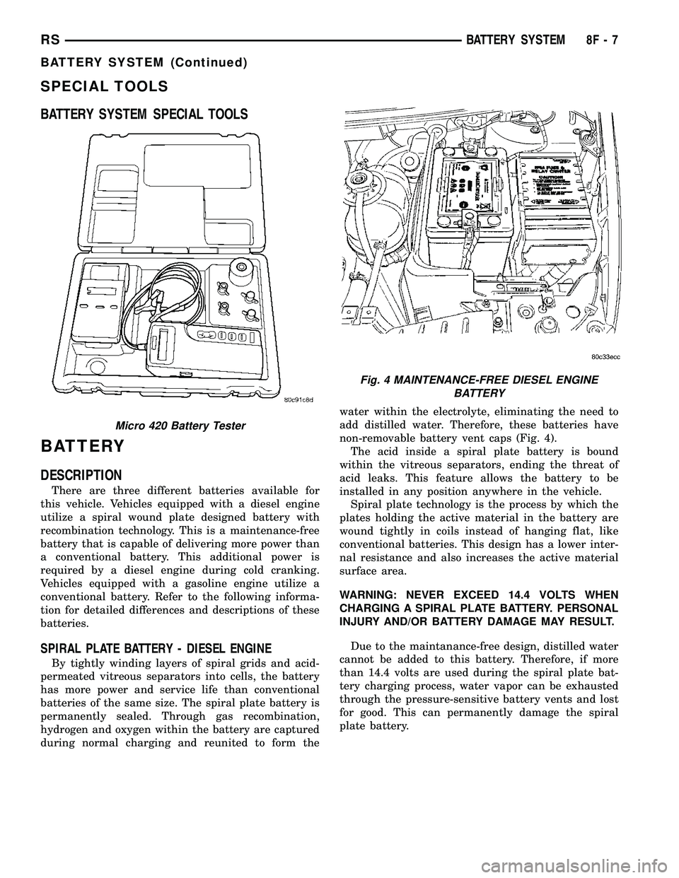
SPECIAL TOOLS
BATTERY SYSTEM SPECIAL TOOLS
BATTERY
DESCRIPTION
There are three different batteries available for
this vehicle. Vehicles equipped with a diesel engine
utilize a spiral wound plate designed battery with
recombination technology. This is a maintenance-free
battery that is capable of delivering more power than
a conventional battery. This additional power is
required by a diesel engine during cold cranking.
Vehicles equipped with a gasoline engine utilize a
conventional battery. Refer to the following informa-
tion for detailed differences and descriptions of these
batteries.
SPIRAL PLATE BATTERY - DIESEL ENGINE
By tightly winding layers of spiral grids and acid-
permeated vitreous separators into cells, the battery
has more power and service life than conventional
batteries of the same size. The spiral plate battery is
permanently sealed. Through gas recombination,
hydrogen and oxygen within the battery are captured
during normal charging and reunited to form thewater within the electrolyte, eliminating the need to
add distilled water. Therefore, these batteries have
non-removable battery vent caps (Fig. 4).
The acid inside a spiral plate battery is bound
within the vitreous separators, ending the threat of
acid leaks. This feature allows the battery to be
installed in any position anywhere in the vehicle.
Spiral plate technology is the process by which the
plates holding the active material in the battery are
wound tightly in coils instead of hanging flat, like
conventional batteries. This design has a lower inter-
nal resistance and also increases the active material
surface area.
WARNING: NEVER EXCEED 14.4 VOLTS WHEN
CHARGING A SPIRAL PLATE BATTERY. PERSONAL
INJURY AND/OR BATTERY DAMAGE MAY RESULT.
Due to the maintanance-free design, distilled water
cannot be added to this battery. Therefore, if more
than 14.4 volts are used during the spiral plate bat-
tery charging process, water vapor can be exhausted
through the pressure-sensitive battery vents and lost
for good. This can permanently damage the spiral
plate battery.
Micro 420 Battery Tester
Fig. 4 MAINTENANCE-FREE DIESEL ENGINE
BATTERY
RSBATTERY SYSTEM8F-7
BATTERY SYSTEM (Continued)
Page 369 of 2339
(6) Pull sensor up out of the chain case cover.Do
not pull on the sensor wiring.There is an O-ring
on the body of the sensor. The O-ring may make
removal difficult. A light tap to top of sensor prior to
removal may reduce force needed for removal.
INSTALLATION
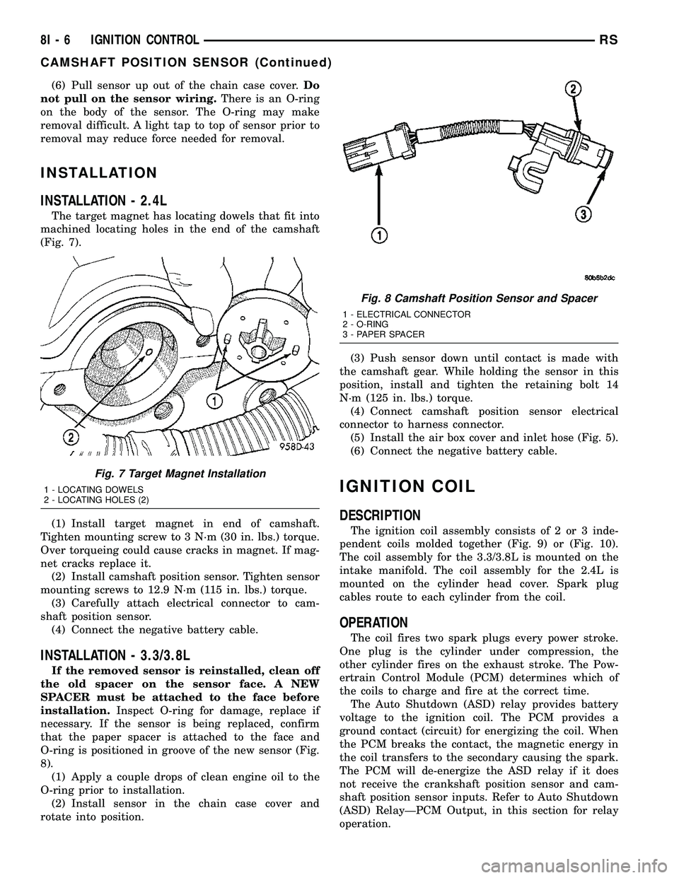
INSTALLATION - 2.4L
The target magnet has locating dowels that fit into
machined locating holes in the end of the camshaft
(Fig. 7).
(1) Install target magnet in end of camshaft.
Tighten mounting screw to 3 N´m (30 in. lbs.) torque.
Over torqueing could cause cracks in magnet. If mag-
net cracks replace it.
(2) Install camshaft position sensor. Tighten sensor
mounting screws to 12.9 N´m (115 in. lbs.) torque.
(3) Carefully attach electrical connector to cam-
shaft position sensor.
(4) Connect the negative battery cable.
INSTALLATION - 3.3/3.8L
If the removed sensor is reinstalled, clean off
the old spacer on the sensor face. A NEW
SPACER must be attached to the face before
installation.Inspect O-ring for damage, replace if
necessary. If the sensor is being replaced, confirm
that the paper spacer is attached to the face and
O-ring is positioned in groove of the new sensor (Fig.
8).
(1) Apply a couple drops of clean engine oil to the
O-ring prior to installation.
(2) Install sensor in the chain case cover and
rotate into position.(3) Push sensor down until contact is made with
the camshaft gear. While holding the sensor in this
position, install and tighten the retaining bolt 14
N´m (125 in. lbs.) torque.
(4) Connect camshaft position sensor electrical
connector to harness connector.
(5) Install the air box cover and inlet hose (Fig. 5).
(6) Connect the negative battery cable.
IGNITION COIL
DESCRIPTION
The ignition coil assembly consists of 2 or 3 inde-
pendent coils molded together (Fig. 9) or (Fig. 10).
The coil assembly for the 3.3/3.8L is mounted on the
intake manifold. The coil assembly for the 2.4L is
mounted on the cylinder head cover. Spark plug
cables route to each cylinder from the coil.
OPERATION
The coil fires two spark plugs every power stroke.
One plug is the cylinder under compression, the
other cylinder fires on the exhaust stroke. The Pow-
ertrain Control Module (PCM) determines which of
the coils to charge and fire at the correct time.
The Auto Shutdown (ASD) relay provides battery
voltage to the ignition coil. The PCM provides a
ground contact (circuit) for energizing the coil. When
the PCM breaks the contact, the magnetic energy in
the coil transfers to the secondary causing the spark.
The PCM will de-energize the ASD relay if it does
not receive the crankshaft position sensor and cam-
shaft position sensor inputs. Refer to Auto Shutdown
(ASD) RelayÐPCM Output, in this section for relay
operation.
Fig. 7 Target Magnet Installation
1 - LOCATING DOWELS
2 - LOCATING HOLES (2)
Fig. 8 Camshaft Position Sensor and Spacer
1 - ELECTRICAL CONNECTOR
2 - O-RING
3 - PAPER SPACER
8I - 6 IGNITION CONTROLRS
CAMSHAFT POSITION SENSOR (Continued)