left forward door CHRYSLER VOYAGER 2005 Service Manual
[x] Cancel search | Manufacturer: CHRYSLER, Model Year: 2005, Model line: VOYAGER, Model: CHRYSLER VOYAGER 2005Pages: 2339, PDF Size: 59.69 MB
Page 177 of 2339
CABLE - PARKING BRAKE
FRONT
REMOVAL
REMOVAL
(1) Raise and support the vehicle. (Refer to
LUBRICATION & MAINTENANCE/HOISTING -
STANDARD PROCEDURE).
(2) Manually release the automatic self-adjusting
mechanism tension of the parking brake lever (pedal)
assembly. (Refer to 5 - BRAKES - STANDARD PRO-
CEDURE).
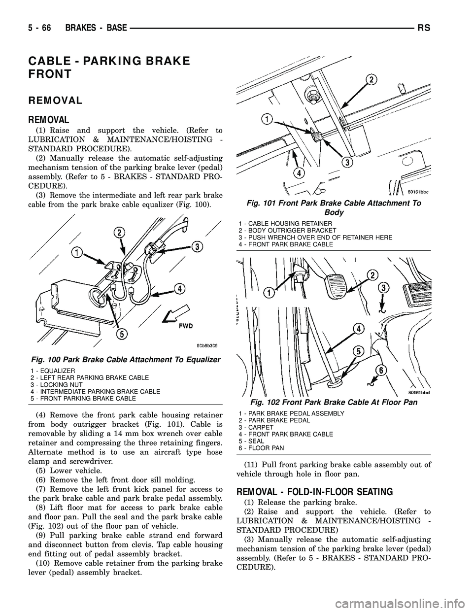
(3)
Remove the intermediate and left rear park brake
cable from the park brake cable equalizer (Fig. 100).
(4) Remove the front park cable housing retainer
from body outrigger bracket (Fig. 101). Cable is
removable by sliding a 14 mm box wrench over cable
retainer and compressing the three retaining fingers.
Alternate method is to use an aircraft type hose
clamp and screwdriver.
(5) Lower vehicle.
(6) Remove the left front door sill molding.
(7) Remove the left front kick panel for access to
the park brake cable and park brake pedal assembly.
(8) Lift floor mat for access to park brake cable
and floor pan. Pull the seal and the park brake cable
(Fig. 102) out of the floor pan of vehicle.
(9) Pull parking brake cable strand end forward
and disconnect button from clevis. Tap cable housing
end fitting out of pedal assembly bracket.
(10) Remove cable retainer from the parking brake
lever (pedal) assembly bracket.(11) Pull front parking brake cable assembly out of
vehicle through hole in floor pan.
REMOVAL - FOLD-IN-FLOOR SEATING
(1) Release the parking brake.
(2) Raise and support the vehicle. (Refer to
LUBRICATION & MAINTENANCE/HOISTING -
STANDARD PROCEDURE)
(3) Manually release the automatic self-adjusting
mechanism tension of the parking brake lever (pedal)
assembly. (Refer to 5 - BRAKES - STANDARD PRO-
CEDURE).
Fig. 100 Park Brake Cable Attachment To Equalizer
1 - EQUALIZER
2 - LEFT REAR PARKING BRAKE CABLE
3 - LOCKING NUT
4 - INTERMEDIATE PARKING BRAKE CABLE
5 - FRONT PARKING BRAKE CABLE
Fig. 101 Front Park Brake Cable Attachment To
Body
1 - CABLE HOUSING RETAINER
2 - BODY OUTRIGGER BRACKET
3 - PUSH WRENCH OVER END OF RETAINER HERE
4 - FRONT PARK BRAKE CABLE
Fig. 102 Front Park Brake Cable At Floor Pan
1 - PARK BRAKE PEDAL ASSEMBLY
2 - PARK BRAKE PEDAL
3 - CARPET
4 - FRONT PARK BRAKE CABLE
5 - SEAL
6 - FLOOR PAN
5 - 66 BRAKES - BASERS
Page 178 of 2339
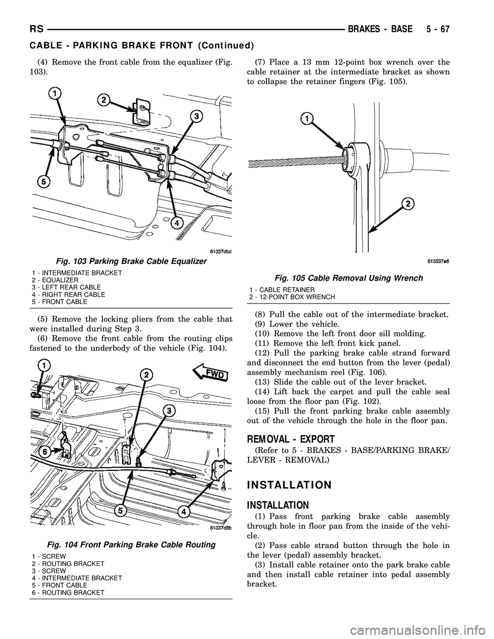
(4) Remove the front cable from the equalizer (Fig.
103).
(5) Remove the locking pliers from the cable that
were installed during Step 3.
(6) Remove the front cable from the routing clips
fastened to the underbody of the vehicle (Fig. 104).(7) Place a 13 mm 12-point box wrench over the
cable retainer at the intermediate bracket as shown
to collapse the retainer fingers (Fig. 105).
(8) Pull the cable out of the intermediate bracket.
(9) Lower the vehicle.
(10) Remove the left front door sill molding.
(11) Remove the left front kick panel.
(12) Pull the parking brake cable strand forward
and disconnect the end button from the lever (pedal)
assembly mechanism reel (Fig. 106).
(13) Slide the cable out of the lever bracket.
(14) Lift back the carpet and pull the cable seal
loose from the floor pan (Fig. 102).
(15) Pull the front parking brake cable assembly
out of the vehicle through the hole in the floor pan.
REMOVAL - EXPORT
(Refer to 5 - BRAKES - BASE/PARKING BRAKE/
LEVER - REMOVAL)
INSTALLATION
INSTALLATION
(1) Pass front parking brake cable assembly
through hole in floor pan from the inside of the vehi-
cle.
(2) Pass cable strand button through the hole in
the lever (pedal) assembly bracket.
(3) Install cable retainer onto the park brake cable
and then install cable retainer into pedal assembly
bracket.
Fig. 103 Parking Brake Cable Equalizer
1 - INTERMEDIATE BRACKET
2 - EQUALIZER
3 - LEFT REAR CABLE
4 - RIGHT REAR CABLE
5 - FRONT CABLE
Fig. 104 Front Parking Brake Cable Routing
1 - SCREW
2 - ROUTING BRACKET
3 - SCREW
4 - INTERMEDIATE BRACKET
5 - FRONT CABLE
6 - ROUTING BRACKET
Fig. 105 Cable Removal Using Wrench
1 - CABLE RETAINER
2 - 12-POINT BOX WRENCH
RSBRAKES - BASE5-67
CABLE - PARKING BRAKE FRONT (Continued)
Page 179 of 2339
(4) Install the end of the park brake cable into the
retainer previously installed into the park brake
pedal bracket.
(5) Install cable strand button into the clevis on
the park brake pedal mechanism.
(6) Install the front park brake cable floor pan seal
into hole in floor pan. Seal is to be installed so the
flange on the seal is flush with the floor pan (Fig.
102). Fold carpeting back down on floor.
(7) Raise vehicle.
(8) Insert brake cable and housing into body out-
rigger bracket making certain that housing retainer
fingers lock the housing firmly into place (Fig. 101).
(9) Manually reset the automatic self-adjusting
mechanism tension of the parking brake lever (pedal)
assembly. (Refer to 5 - BRAKES - STANDARD PRO-
CEDURE).
(10) Assemble the park brake cables onto the park
brake cable equalizer (Fig. 100).
(11) Lower vehicle and apply the park brake pedal
1 time. This will seat the parking brake cables.
INSTALLATION - FOLD-IN-FLOOR SEATING
(1) Pass most of the front parking brake cable
assembly down through hole in the floor pan from
inside the vehicle.
(2) Pass the lever-end cable strand button through
the hole in the lever (pedal) assembly bracket.
(3) Install the end of the cable housing into the
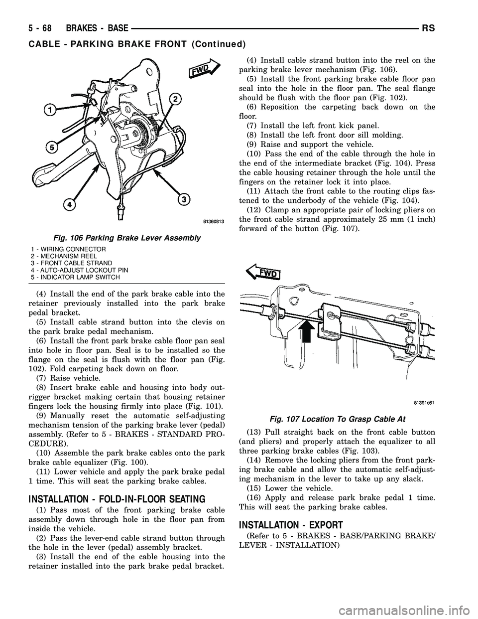
retainer installed into the park brake pedal bracket.(4) Install cable strand button into the reel on the
parking brake lever mechanism (Fig. 106).
(5) Install the front parking brake cable floor pan
seal into the hole in the floor pan. The seal flange
should be flush with the floor pan (Fig. 102).
(6) Reposition the carpeting back down on the
floor.
(7) Install the left front kick panel.
(8) Install the left front door sill molding.
(9) Raise and support the vehicle.
(10) Pass the end of the cable through the hole in
the end of the intermediate bracket (Fig. 104). Press
the cable housing retainer through the hole until the
fingers on the retainer lock it into place.
(11) Attach the front cable to the routing clips fas-
tened to the underbody of the vehicle (Fig. 104).
(12) Clamp an appropriate pair of locking pliers on
the front cable strand approximately 25 mm (1 inch)
forward of the button (Fig. 107).
(13) Pull straight back on the front cable button
(and pliers) and properly attach the equalizer to all
three parking brake cables (Fig. 103).
(14) Remove the locking pliers from the front park-
ing brake cable and allow the automatic self-adjust-
ing mechanism in the lever to take up any slack.
(15) Lower the vehicle.
(16) Apply and release park brake pedal 1 time.
This will seat the parking brake cables.
INSTALLATION - EXPORT
(Refer to 5 - BRAKES - BASE/PARKING BRAKE/
LEVER - INSTALLATION)
Fig. 106 Parking Brake Lever Assembly
1 - WIRING CONNECTOR
2 - MECHANISM REEL
3 - FRONT CABLE STRAND
4 - AUTO-ADJUST LOCKOUT PIN
5 - INDICATOR LAMP SWITCH
Fig. 107 Location To Grasp Cable At
5 - 68 BRAKES - BASERS
CABLE - PARKING BRAKE FRONT (Continued)
Page 186 of 2339
INSTALLATION - LEFT REAR
(1) Install the rear parking brake cable in the
brake support plate. Insert cable housing retainer
into brake support plate making certain that cable
housing retainer fingers lock the housing and
retainer firmly into place.
(2) Attach the parking brake cable onto the park
brake actuator lever.
(3) Install the brake shoes on the rear brake sup-
port plate. (Refer to 5 - BRAKES/HYDRAULIC/ME-
CHANICAL/BRAKE PADS/SHOES -
INSTALLATION).
(4) Insert cable housing retainer into body outrig-
ger bracket making certain that cable housing
retainer fingers lock the housing firmly into place.
(5) Connect rear parking brake cable to the equal-
izer bracket (Fig. 115).
(6) Install brake drum, and wheel and tire assem-
bly.
(7) Remove the locking pliers from the front park
brake cable. This will automatically adjust the park
brake cables.
(8) Apply and release park brake pedal 1 time.
This will seat the park brake cables.
INSTALLATION - FOLD-IN-FLOOR SEATING
(1) Pass the leading end of the rear parking brake
cable through the hole in the end of the intermediate
bracket (Fig. 123). Press the cable housing retainer
through the hole until the fingers on the retainer
lock it into place.
(2) Route the cable back toward the brake assem-
bly placing it in the routing clip fastened to the
underbody of the vehicle (Fig. 119). Make sure to
stay to the inside of the left stabilizer bar link while
routing either cable.
(3) If the right rear cable is being serviced, install
screws, attaching the cable routing clamps to the
rear axle (Fig. 120).
(4) Pass the cable through the hole in the brake
adapter and hook the cable eyelet to the shoe lever
(Fig. 121).
(5) Install the screw fastening the cable to the rear
brake adapter (Fig. 121).
(6) Pull straight back on the front cable button
(and pliers) and properly attach the equalizer to all
three parking brake cables (Fig. 118).
(7) Remove the locking pliers from the front park-
ing brake cable and allow the automatic self-adjust-
ing mechanism in the lever to take up any slack.
(8) Lower the vehicle.
(9) Apply and release park brake pedal 1 time.
This will seat the parking brake cables.
LEVER - PARKING BRAKE
REMOVAL
(1) Manually release the automatic self-adjusting
mechanism tension of the parking brake lever (pedal)
assembly. (Refer to 5 - BRAKES/PARKING BRAKE -
STANDARD PROCEDURE).
(2) Disconnect negative (ground) cable from the
battery and isolate cable from battery terminal.
(3) Remove sill scuff plate from left door sill.
(4) Remove the left side kick panel.
(5) Remove the steering column cover from the
lower instrument panel.
(6) Remove the reinforcement from the lower
instrument panel.
(7) Remove the three bolts mounting the wiring
junction block to the instrument panel.
NOTE: When removing the lower mounting bolt,
push the park brake pedal down 5 clicks to access
the lower mounting bolt.
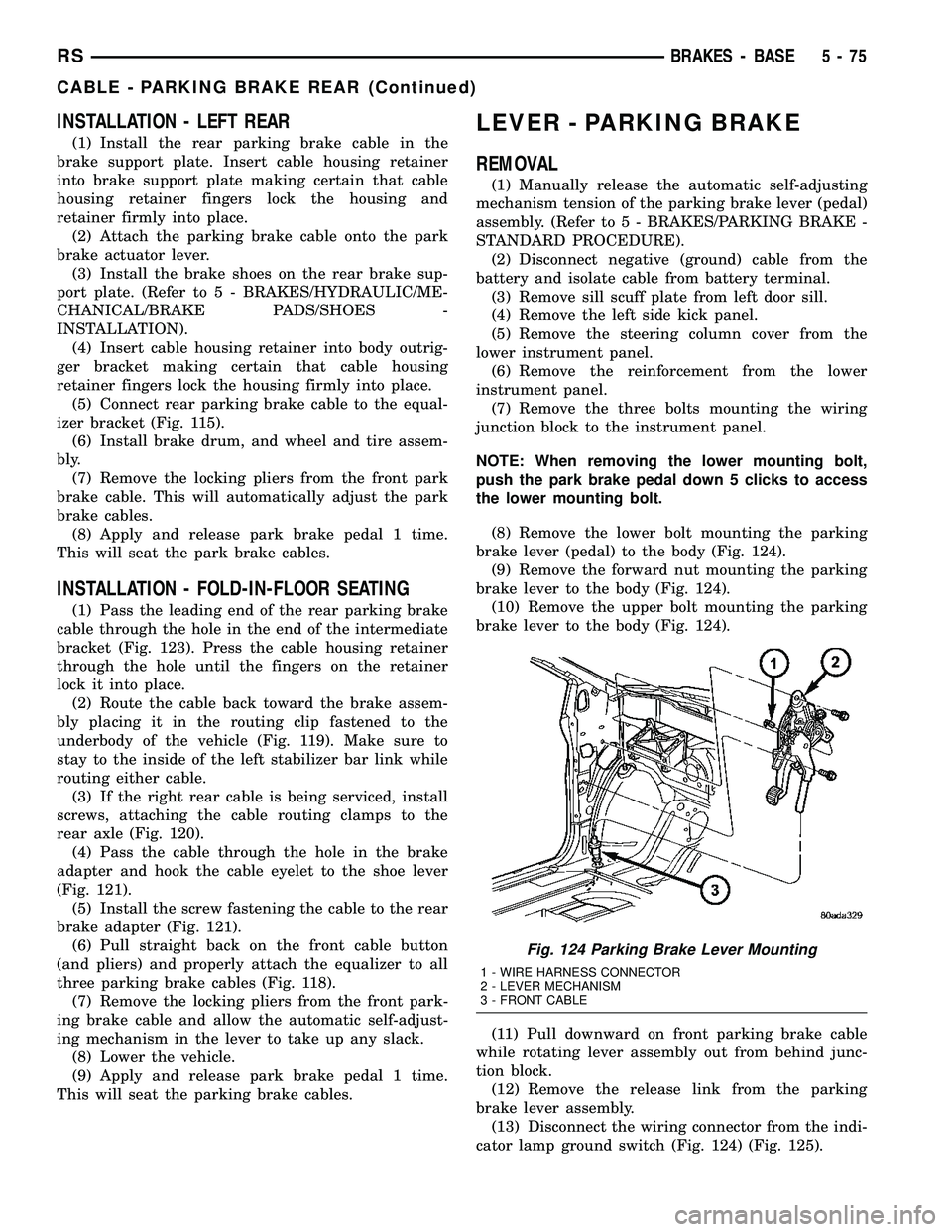
(8) Remove the lower bolt mounting the parking
brake lever (pedal) to the body (Fig. 124).
(9) Remove the forward nut mounting the parking
brake lever to the body (Fig. 124).
(10) Remove the upper bolt mounting the parking
brake lever to the body (Fig. 124).
(11) Pull downward on front parking brake cable
while rotating lever assembly out from behind junc-
tion block.
(12) Remove the release link from the parking
brake lever assembly.
(13) Disconnect the wiring connector from the indi-
cator lamp ground switch (Fig. 124) (Fig. 125).
Fig. 124 Parking Brake Lever Mounting
1 - WIRE HARNESS CONNECTOR
2 - LEVER MECHANISM
3 - FRONT CABLE
RSBRAKES - BASE5-75
CABLE - PARKING BRAKE REAR (Continued)
Page 187 of 2339
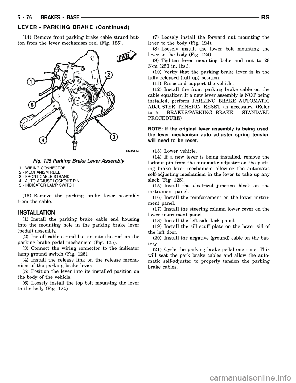
(14) Remove front parking brake cable strand but-
ton from the lever mechanism reel (Fig. 125).
(15) Remove the parking brake lever assembly
from the cable.
INSTALLATION
(1) Install the parking brake cable end housing
into the mounting hole in the parking brake lever
(pedal) assembly.
(2) Install cable strand button into the reel on the
parking brake pedal mechanism (Fig. 125).
(3) Connect the wiring connector to the indicator
lamp ground switch (Fig. 125).
(4) Install the release link on the release mecha-
nism of the parking brake lever.
(5) Position the lever into its installed position on
the body of the vehicle.
(6) Loosely install the top bolt mounting the lever
to the body (Fig. 124).(7) Loosely install the forward nut mounting the
lever to the body (Fig. 124).
(8) Loosely install the lower bolt mounting the
lever to the body (Fig. 124).
(9) Tighten lever mounting bolts and nut to 28
N´m (250 in. lbs.).
(10) Verify that the parking brake lever is in the
fully released (full up) position.
(11) Raise and support the vehicle.
(12) Install the front parking brake cable on the
cable equalizer. If a new lever assembly is NOT being
installed, perform PARKING BRAKE AUTOMATIC
ADJUSTER TENSION RESET as necessary. (Refer
to 5 - BRAKES/PARKING BRAKE - STANDARD
PROCEDURE)
NOTE: If the original lever assembly is being used,
the lever mechanism auto adjuster spring tension
will need to be reset.
(13) Lower vehicle.
(14) If a new lever is being installed, remove the
lockout pin from the automatic adjuster on the park-
ing brake lever mechanism allowing the automatic
self-adjusting mechanism in the lever to take up any
slack (Fig. 125).
(15) Install the electrical junction block on the
instrument panel.
(16) Install the reinforcement on the lower instru-
ment panel.
(17) Install the steering column lower cover on the
lower instrument panel.
(18) Install the left side kick panel.
(19) Install the sill scuff plate on the lower sill of
the left door.
(20) Install the negative (ground) cable on the bat-
tery.
(21) Cycle the parking brake pedal one time. This
will seat the park brake cables and allow the auto-
matic self-adjuster to properly tension the parking
brake cables.
Fig. 125 Parking Brake Lever Assembly
1 - WIRING CONNECTOR
2 - MECHANISM REEL
3 - FRONT CABLE STRAND
4 - AUTO-ADJUST LOCKOUT PIN
5 - INDICATOR LAMP SWITCH
5 - 76 BRAKES - BASERS
LEVER - PARKING BRAKE (Continued)
Page 519 of 2339

(38) Remove the two passenger airbag to instru-
ment panel cover/pad retaining screws.
(39) Remove the three passenger airbag to instru-
ment panel reinforcement retaining bolts.
(40) Pull rearward slightly on the instrument
panel cover/pad to maneuver passenger airbag out
from reinforcement and instrument panel.
INSTALLATION
DEPLOYED AIRBAG
Transfer all reusable components to the new
instrument panel.
(1) Install new Passenger Airbag into instrument
panel.
(2) Install airbag attaching bolts to the instrument
panel.
(a) Torque the two bolts at instrument panel
retainer bosses to 2.7 .5 N´m (24 5 in. lbs.).
(b) Torque the three bolts that attach the pas-
senger airbag to cross-car beam to 10 2 N´m (90
15 in. lbs.).
(3) Connect yellow wire connector to passenger air-
bag and affix connector to instrument panel rein-
forcement with push pins.
(4) Install Instrument panel (Refer to 23 - BODY/
INSTRUMENT PANEL/INSTRUMENT PANEL
ASSEMBLY - INSTALLATION).
WARNING: Do not connect the battery negative
cable (Refer to 8 - ELECTRICAL/RESTRAINTS -
DIAGNOSIS AND TESTING - AIRBAG SYSTEM). Per-
sonal injury or death may result if the system test
is not performed first.
UNDEPLOYED AIRBAG
(1) Pull rearward slightly on the instrument panel
cover/pad to maneuver passenger airbag up onto
reinforcement and instrument panel.
(2) Install the three passenger airbag to instru-
ment panel reinforcement retaining bolts but leave
loose. This will help align the passenger airbag for
the cover/pad fit.
(3) Install the two passenger airbag to instrument
panel cover/pad retaining screws. Torque screws to
2.7 .5 N´m (24 5 in. lbs.).
NOTE: Insure that the instrument panel cover/pad
locator pins are indexed properly at center stack
area prior to reassembly.
(4) Tighten the three passenger airbag to instru-
ment panel reinforcement retaining bolts. Torque
bolts to 10 2 N´m (90 15 in. lbs.).(5) Connect the passenger airbag electrical connec-
tor. Install the connector onto the instrument panel
reinforcement with the push-pin fasteners.
(6) Roll the instrument panel forward lifting
slightly so as to seat the instrument panel air distri-
bution duct on top of the HVAC unit properly to
avoid any leaks or damage to the seal.
(7) Install six upper fence line instrument panel
retaining bolts.
(8) Install three right side instrument panel A-pil-
lar retaining bolts and tighten the right instrument
panel roll down bolt. Install the smaller 10 mm bolt
first to align the instrument panel properly.
(9) Install three left side instrument panel A-pillar
retaining bolts and tighten the left instrument panel
roll down bolt. Install the smaller 10 mm bolt first to
align the instrument panel properly.
(10) Install seven lower instrument panel cover/
pad retaining screws.
(11) Install four screws along top front edge of
instrument panel cover/pad.
(12) Install one far left instrument panel speaker
retaining screw.
(13) Install wiring connectors to radio. Install
radio and four retaining screws.
(14) Connect glove box lamp wiring connector and
place right lower instrument panel trim (glove box
surround) into position.
(15) Install nineteen right lower instrument panel
trim (glove box surround) and install panel screws.
(16) Slide cup holder assembly into instrument
panel.
(17) Install center bezel wiring connectors to
HVAC control and switch assembly (hazard, rear
wiper/washer, heated seats).
(18) Install instrument panel center bezel by align-
ing slots and firmly snapping into place.
(19) Install two screws to instrument panel center
bezel.
(20) Align filler bezel above cup holder over retain-
ing slots and firmly snap into place.
(21) Place instrument panel top cover into position
and firmly snap down rear edge of top cover.
(22) Install glove box. Align hinges, snap into
place, roll glove box upwards and push in sides to
fully install.
(23) Align right side upper A-pillar trim over
retaining slots and firmly snap into place.
(24) Align right A-pillar lower extension trim over
retaining slots and firmly snap into place.
(25) Align right instrument panel end cap over
retaining slots and firmly snap into place.
(26) Align right cowl panel over retaining slots and
firmly snap into place.
(27) Align right front door sill plate over retaining
slots and firmly snap into place.
8O - 32 RESTRAINTSRS
PASSENGER AIRBAG (Continued)
Page 525 of 2339

INSTALLATION
(1) Push belt through seat cushion.
(2) While looking at the bottom of the seat, locate
retaining bolt hole on the left side of the seat riser.
Install retaining bolt into seat riser (Fig. 45). Torque
anchor bolt to 39 N´m (29 ft. lbs.).
(3) Place seat into track and on front anchors.
(4) Pull #3 strap and install seat onto latching
area.
(5) Pull seat assembly down firmly and snap into
track.
(6) Pull handle #1 and fold seat back rearward.
(7) Close rear liftgate.
SEAT BELT HEIGHT
ADJUSTER-BORC-PILLAR
REMOVAL
(1) Remove turning loop retaining bolt.
(2) Remove B or C-pillar trim cover.
(3) Remove two screws attaching shoulder belt
height adjuster to pillar.
(4) Remove height adjuster from vehicle.
INSTALLATION
(1) Place height adjuster into position.
(2) Install screws attaching shoulder belt height
adjuster to pillar.
(3) Install B or C-pillar trim cover.
(4) Install turning loop to height adjuster. Torque
anchor bolt to 39 N´m (29 ft. lbs.).
SEAT BELT HEIGHT
ADJUSTER KNOB
REMOVAL
(1) Disengage clips attaching clam shell cover to
seat belt turning loop and open cover.
(2) Using a trim tool (special tool #C-4755), gently
pry knob from seat belt height adjuster.
INSTALLATION
(1) Place seat belt height adjuster knob in position
on height adjuster.
(2) Firmly push knob on until retainers engage.
(3) Reinstall turning loop clam shell cover.
(4) Verify seat belt operation. Make sure it moves
through loop without binding.
SEAT BELT & RETRACTOR -
OUTBOARD - FRONT
REMOVAL
(1) Open door.
(2) Move seat all the way forward.
(3) Open hood.
(4) Disconnect and isolate the battery negative
cable.
(5)
WARNING: Wait two minutes for the airbag system
reserve capacitor to discharge before beginning
any airbag system or component service. Failure to
do so may result in accidental airbag deployment,
personal injury or death.
(6) Remove shoulder harness height adjuster knob
by pulling it straight away from adjuster (Fig. 48).
(7) Remove cover from seat belt turning loop (Fig.
48).
(8) Remove bolt attaching turning loop to shoulder
belt height adjuster (Fig. 48).
(9) Remove upper B-pillar trim cover (Fig. 48).
NOTE: If equipped with the Occupant Classification
System (OCS), there is a Belt Tension Sensor
located on the lower seat belt anchor on the pas-
senger front seat belt.
Fig. 48 SEAT BELT - OUTBOARD FRONT
1 - B-PILLAR TRIM LOWER
2 - BELT
3 - B-PILLAR TRIM UPPER
4 - HEIGHT ADJUSTER
5 - KNOB
6 - B-PILLAR TRIM LOWER
7 - FLOOR ANCHOR
8 - FLOOR ANCHOR
9 - 30É OUTBOARD
10 - RETRACTOR
8O - 38 RESTRAINTSRS
SEAT BELT BUCKLE - SECOND ROW INBOARD - 50/50 BENCH (Continued)
Page 1809 of 2339
(3) Position door rearward of the sliding door open-
ing.
CAUTION: Do not allow the center hinge roller to
contact the quarter glass. Glass can break.
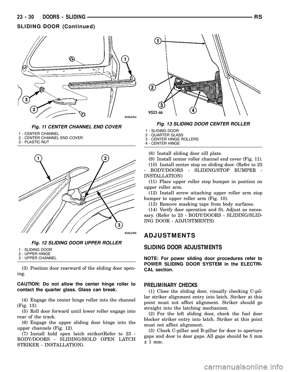
(4) Engage the center hinge roller into the channel
(Fig. 13).
(5) Roll door forward until lower roller engage into
rear of the track.
(6) Engage the upper sliding door hinge into the
upper channels (Fig. 12).
(7) Install hold open latch striker(Refer to 23 -
BODY/DOORS - SLIDING/HOLD OPEN LATCH
STRIKER - INSTALLATION).(8) Install sliding door sill plate.
(9) Install center roller channel end cover (Fig. 11).
(10) Install center stop on sliding door. (Refer to 23
- BODY/DOORS - SLIDING/STOP BUMPER -
INSTALLATION)
(11) Place upper roller stop bumper in position on
upper roller arm.
(12) Install screw attaching upper roller arm stop
bumper to upper roller arm (Fig. 10).
(13) Remove masking tape from body surfaces.
(14) Verify door operation and fit. Adjust as neces-
sary. (Refer to 23 - BODY/DOORS - SLIDING/SLID-
ING DOOR - ADJUSTMENTS)
ADJUSTMENTS
SLIDING DOOR ADJUSTMENTS
NOTE: For power sliding door procedures refer to
POWER SLIDING DOOR SYSTEM in the ELECTRI-
CAL section.
PRELIMINARY CHECKS
(1) Close the sliding door, visually checking C-pil-
lar striker alignment entry into latch. Striker at this
point must not affect alignment. Striker should go
straight into the latching mechanism.
(2) For the left sliding door, check the fuel door
blocker striker entry into latch. Striker at this point
must not affect alignment.
(3) Check C-pillar and B-pillar for door to aperture
gaps and door to door gaps. All gaps should be 5 mm
1 mm.
Fig. 11 CENTER CHANNEL END COVER
1 - CENTER CHANNEL
2 - CENTER CHANNEL END COVER
3 - PLASTIC NUT
Fig. 12 SLIDING DOOR UPPER ROLLER
1 - SLIDING DOOR
2 - UPPER HINGE
3 - UPPER CHANNEL
Fig. 13 SLIDING DOOR CENTER ROLLER
1 - SLIDING DOOR
2 - QUARTER GLASS
3 - CENTER HINGE ROLLERS
4 - CENTER HINGE
23 - 30 DOORS - SLIDINGRS
SLIDING DOOR (Continued)
Page 1877 of 2339

(4) Remove bolt attaching second row seat belt,
anchor to quarter on short wheel base vehicle.
(5)
Disengage hidden clips attaching trim to D-pillar.
(6) Remove D-pillar trim panel from D-pillar.
(7) Disconnect speaker wire connector, if equipped.
(8) Pass second row seat belt, if equipped, through
slot in trim panel on short wheel base vehicle.
(9) Remove D-pillar trim from vehicle.
INSTALLATION
(1) Position D-pillar trim on vehicle.
(2) Pass second row seat belt, if equipped, through
slot in trim panel on short wheel base vehicle.
(3) Connect speaker wire connector to speaker, if
equipped.
(4) Align locating pins on backside of trim panel to
mating holes in D-pillar.
(5) Engage hidden clips attaching trim to D-pillar.
(6) Install screws attaching trim panel to attach-
ing bracket on short wheel base vehicle.
(7) Install quarter trim bolster on short wheel base
vehicle.
(8) Install bolt to attach second row seat belt, if
equipped, anchor to quarter on short wheel base
vehicle. Tighten all seat belt bolts to 39 N´m (29 ft.
lbs.) torque.
(9) Install second row seat belt turning loop on
long wheel base vehicle.
(10) Install liftgate sill plate.
(11) Install rear header trim cover.
SECOND ROW FLOOR TUB
CARPET INSERT - FOLD-IN-
FLOOR
REMOVAL
(1) Move both front seats to the full forward posi-
tion.(2) Fold second row seats into the floor well.
(3) Remove rear carpet ring and cover from vehi-
cle. (Refer to 23 - BODY/INTERIOR/REAR CARPET
RING AND COVER ASSEMBLY - REMOVAL).
(4) Remove second row seat from vehicle. Repeat
operation for other side, if necessary.
(5) Remove second row floor tub insert(s) from
vehicle (Fig. 35).
INSTALLATION
(1) Place second row floor tub insert(s) into posi-
tion (Fig. 35).
(2) Place seat(s) into position and install seat.
(Refer to 23 - BODY/SEATS/SEAT - INSTALLA-
TION). Repeat operation for other side, if necessary.
(3) Install rear carpet ring and cover position.
(Refer to 23 - BODY/INTERIOR/REAR CARPET
RING AND COVER - INSTALLATION).
(4) Open second row seats into the upright posi-
tion.
(5) Move both front seats to the normal position.
SLIDING DOOR SILL PLATE
REMOVAL
(1) Disengage hidden clips holding sill plate to
sliding door opening sill.
(2) Disengage hooks holding outside edge of sill
plate to door sill (Fig. 36).
(3) Remove sill plate from vehicle.
Fig. 34 REAR VIEW MIRROR
1 - MIRROR
2 - WINDSHIELD
Fig. 35 SECOND ROW FLOOR TUB INSERT
1 - WELD STUDS
2 - RIGHT TUB INSERT
3 - SECOND ROW SEAT TUB
4 - LEFT TUB INSERT
23 - 98 INTERIORRS
RIGHT D-PILLAR TRIM PANEL (Continued)
Page 2321 of 2339

LWB - INSTALLATION, SEAT BELT &RETRACTOR - SECOND ROW - RIGHT
OUTBOARD WITH REAR HVAC ..........8O-41
LWB - REMOVAL, SEAT BELT & RETRACTOR - SECOND ROW - RIGHT
OUTBOARD WITH REAR HVAC ..........8O-41
MACHINING - STANDARD PROCEDURE, BRAKE ROTOR ....................... 5-58
MAIN BEARING FITTING - STANDARD PROCEDURE ........................ 9-125
MAIN BEARINGS - INSTALLATION, CRANKSHAFT ....................... 9-127
MAIN BEARINGS - REMOVAL, CRANKSHAFT ....................... 9-127
MANAGER - DESCRIPTION, TASK ........25-25
MANAGER - OPERATION, TASK .........25-25
MANIFOLD - CLEANING, EXHAUST ........9-63
MANIFOLD - DESCRIPTION, INTAKE . . 9-147,9-60
MANIFOLD - INSPECTION, EXHAUST ......9-63
MANIFOLD - INSTALLATION, EXHAUST ....9-63
MANIFOLD - INSTALLATION, LOWER INTAKE ............................ 9-151
MANIFOLD - INSTALLATION, UPPER INTAKE ............................ 9-149
MANIFOLD - LEFT - CLEANING, EXHAUST ........................... 9-154
MANIFOLD - LEFT - INSPECTION, EXHAUST ........................... 9-155
MANIFOLD - LEFT - INSTALLATION, EXHAUST ........................... 9-155
MANIFOLD - LEFT - REMOVAL, EXHAUST . 9-154
MANIFOLD - LOWER - CLEANING, INTAKE ............................ 9-151
MANIFOLD - LOWER - INSPECTION, INTAKE ........................ 9-151,9-62
MANIFOLD - LOWER - INSTALLATION, INTAKE ............................. 9-62
MANIFOLD - LOWER - REMOVAL, INTAKE ............................. 9-62
MANIFOLD - REMOVAL, EXHAUST ........9-63
MANIFOLD - REMOVAL, LOWER INTAKE . . 9-150
MANIFOLD - REMOVAL, UPPER INTAKE . . . 9-148
MANIFOLD - RIGHT - CLEANING, EXHAUST ........................... 9-153
MANIFOLD - RIGHT - INSPECTION, EXHAUST ........................... 9-153
MANIFOLD - RIGHT - INSTALLATION, EXHAUST ........................... 9-153
MANIFOLD - RIGHT - REMOVAL, EXHAUST ........................... 9-152
MANIFOLD - UPPER - INSPECTION, INTAKE ............................. 9-61
MANIFOLD - UPPER - INSTALLATION, INTAKE ............................. 9-61
MANIFOLD - UPPER - REMOVAL, INTAKE . . 9-60
MANIFOLD LEAKS - DIAGNOSIS AND TESTING, INTAKE ................ 9-147,9-60
MANIFOLD STRIPPED THREAD REPAIR - STANDARD PROCEDURE ...............9-147
MANIFOLD VACUUM PORT REPAIR - STANDARD PROCEDURE, INTAKE ........9-148
MANUAL - INSTALLATION, WINDOW REGULATOR ........................ 23-23
MANUAL - OCS - INSTALLATION, FRONT SEAT RISER ........................ 23-123
MANUAL - OCS - REMOVAL, FRONT SEAT RISER ........................ 23-123
MANUAL - REMOVAL, WINDOW REGULATOR ........................ 23-22
MANUAL ADJUSTER - INSTALLATION, FRONT SEAT TRACK .................23-126
MANUAL ADJUSTER - REMOVAL, FRONT SEAT TRACK ....................... 23-125
MANUAL DUAL ZONE, DESCRIPTION ......24-2
MANUAL DUAL ZONE, OPERATION ........24-5
MANUAL SINGLE ZONE, DESCRIPTION ....24-2
MANUAL SINGLE ZONE, OPERATION ......24-4
MANUAL TEMPERATURE CONTROL SYSTEM, OPERATION ................24-113
MANUAL THREE ZONE, DESCRIPTION .....24-2
MANUAL THREE ZONE, OPERATION .......24-5
MAP SENSOR - DESCRIPTION ..........14-34
MAP SENSOR - OPERATION ............14-34
MASTER CYLINDER BLEEDING - STANDARD PROCEDURE ................5-36
MASTER CYLINDER (FLUID RESERVOIR) - ASSEMBLY ......................... 5-39MASTER CYLINDER (FLUID RESERVOIR)
- DISASSEMBLY ...................... 5-38
MATCH MOUNTING - STANDARD PROCEDURE, TIRE AND WHEEL ..........22-7
MATS - INSTALLATION, CARPETS AND FLOOR ............................. 23-81
MATS - REMOVAL, CARPETS AND FLOOR ............................. 23-81
MEASUREMENT - STANDARD PROCEDURE, CURB HEIGHT .............2-55
MEASUREMENT AND ADJUSTMENT, ADJUSTMENTS - DIFFERENTIAL
BEARING PRELOAD ................... 21-79
MEASUREMENTS - SPECIFICATIONS, GAP AND FLUSH .................... 23-177
MEASURING BEARING CLEARANCE USING PLASTIGAGE - STANDARD
PROCEDURE ..................... 9-12,9-86
MEASURING CAMSHAFT END PLAY - STANDARD PROCEDURE ................9-29
MEASURING CONNECTING ROD BEARING CLEARANCE - STANDARD
PROCEDURE ........................ 9-123
MEASURING CRANKSHAFT END PLAY - STANDARD PROCEDURE ...............9-128
MEASURING TIMING CHAIN WEAR - STANDARD PROCEDURE ...............9-155
MECHANICAL - DIAGNOSIS AND TESTING, ENGINE DIAGNOSIS ........9-6,9-82
MECHANISM -SECOND ROW -FOLD-IN- FLOOR - INSTALLATION, SEAT
RECLINER/FORWARD FOLDING ........23-137
MECHANISM -SECOND ROW -FOLD-IN- FLOOR - REMOVAL, SEAT RECLINER/
FORWARD FOLDING .................23-137
MECHANISM -THIRD ROW -FOLD-IN- FLOOR - INSTALLATION, SEAT
RECLINER/FOLD FORWARD ...........23-160
MECHANISM -THIRD ROW -FOLD-IN- FLOOR - REMOVAL, SEAT RECLINER/
FOLD FORWARD .................... 23-160
MEMORIES, OPERATION - FUEL CORRECTION OR ADAPTIVE ............14-24
MEMORY SEAT/MIRROR MODULE - DESCRIPTION ........................ 8E-9
MEMORY SEAT/MIRROR MODULE - OPERATION .......................... 8E-9
MEMORY SEAT/MIRROR MODULE, DIAGNOSIS AND TESTING ..............8E-9
MEMORY SWITCH - DESCRIPTION ......8N-36
MEMORY SWITCH - OPERATION ........8N-36
MEMORY SWITCH, DIAGNOSIS AND TESTING ........................... 8N-37
MEMORY SYSTEM, DESCRIPTION .......8N-32
MEMORY SYSTEM, DIAGNOSIS AND TESTING ........................... 8N-33
MEMORY SYSTEM, OPERATION .........8N-33
MESSAGE CENTER - INSTALLATION ......8M-1
MESSAGE CENTER - REMOVAL ..........8M-1
MICRO 420 BATTERY TESTER, STANDARD PROCEDURE ...............8F-15
MINI-TRIP COMPUTER, DIAGNOSIS AND TESTING - COMPASS .................8M-10
MIRROR - DESCRIPTION, AUTOMATIC DAY / NIGHT ........................ 8N-28
MIRROR - INSTALLATION, GLASS- OUTSIDE REARVIEW .................. 23-61
MIRROR - INSTALLATION, REAR VIEW . . . 23-97
MIRROR - INSTALLATION, SIDE VIEW ....23-60
MIRROR - OPERATION, AUTOMATIC DAY / NIGHT ............................ 8N-28
MIRROR - REMOVAL, GLASS-OUTSIDE REARVIEW .......................... 23-61
MIRROR - REMOVAL, REAR VIEW .......23-97
MIRROR - REMOVAL, SIDE VIEW ........23-60
MIRROR - REMOVAL, SIDEVIEW ........8N-30
MIRROR, DIAGNOSIS AND TESTING - AUTOMATIC DAY / NIGHT ..............8N-28
MIRROR SWITCH - EXPORT - DESCRIPTION, POWER FOLDAWAY ......8N-29
MIRROR SWITCH - EXPORT - INSTALLATION, POWER FOLDAWAY ......8N-30
MIRROR SWITCH - EXPORT - OPERATION, POWER FOLDAWAY ........8N-29
MIRROR SWITCH - EXPORT - REMOVAL, POWER FOLDAWAY .................. 8N-29
MIRRORS - DESCRIPTION, HEATED .......8G-6
MIRRORS - DESCRIPTION, POWER ......8N-26 MIRRORS - OPERATION, HEATED
........8G-6
MIRRORS - OPERATION, POWER ........8N-26
MIRRORS, DIAGNOSIS AND TESTING - POWER ............................ 8N-27
MODE DOOR ACTUATOR - DESCRIPTION . . 24-29
MODE DOOR ACTUATOR - INSTALLATION ....................... 24-30
MODE DOOR ACTUATOR - OPERATION . . . 24-29
MODE DOOR ACTUATOR - REAR - DESCRIPTION ....................... 24-39
MODE DOOR ACTUATOR - REAR - INSTALLATION ....................... 24-40
MODE DOOR ACTUATOR - REAR - OPERATION ......................... 24-39
MODE DOOR ACTUATOR - REAR - REMOVAL .......................... 24-39
MODE DOOR ACTUATOR - REMOVAL .....24-29
MODE, OPERATION - DRB III TS TAT E
DISPLAY TEST ....................... 25-10
MODELS, INSTALLATION - RG ..........24-27
MODELS, INSTALLATION - RS ..........24-28
MODELS, REMOVAL - RG ..............24-27
MODELS, REMOVAL - RS ..............24-27
MODES OF OPERATION - OPERATION ....14-22
MODULE - BLOWER MOTOR - DESCRIPTION, POWER ................24-30
MODULE - BLOWER MOTOR - INSTALLATION, POWER ...............24-31
MODULE - BLOWER MOTOR - OPERATION, POWER .................. 24-30
MODULE - BLOWER MOTOR - REMOVAL, POWER ................... 24-30
MODULE - DESCRIPTION, BODY CONTROL ........................... 8E-2
MODULE - DESCRIPTION, FRONT CONTROL ........................... 8E-7
MODULE - DESCRIPTION, FUEL PUMP ....14-8
MODULE - DESCRIPTION, HEATED SEAT . . . 8E-8
MODULE - DESCRIPTION, INTEGRATED POWER ..........................8W -97-1
MODULE - DESCRIPTION, MEMORY SEAT/MIRROR ........................ 8E-9
MODULE - DESCRIPTION, OCCUPANT CLASSIFICATION ..................... 8O-25
MODULE - DESCRIPTION, PARK ASSIST . . . 8B-4
MODULE - DESCRIPTION, POWER LIFTGATE CONTROL .................. 8E-10
MODULE - DESCRIPTION, SENTRY KEY REMOTE ENTRY ...................... 8Q-3
MODULE - DESCRIPTION, SLIDING DOOR CONTROL ..................... 8E-18
MODULE - DIAGNOSIS AND TESTING, SENTRY KEY REMOTE ENTRY ...........8Q-5
MODULE - EXPORT - DESCRIPTION, ANTENNA .......................... 8A-10
MODULE - EXPORT - OPERATION, ANTENNA .......................... 8A-10
MODULE - INSTALLATION, BODY CONTROL ........................... 8E-4
MODULE - INSTALLATION, HANDS FREE . . . 8T-3
MODULE - INSTALLATION, INTEGRATED POWER ..........................8W -97-2
MODULE - INSTALLATION, OCCUPANT CLASSIFICATION ..................... 8O-26
MODULE - INSTALLATION, PARK ASSIST . . 8B-6
MODULE - INSTALLATION, SENTRY KEY REMOTE ENTRY ...................... 8Q-6
MODULE - INSTALLATION, WIPER .......8R-14
MODULE - OPERATION, BODY CONTROL . . . 8E-3
MODULE - OPERATION, FRONT CONTROL ........................... 8E-7
MODULE - OPERATION, FUEL PUMP ......14-9
MODULE - OPERATION, HEATED SEAT .....8E-8
MODULE - OPERATION, INTEGRATED POWER ..........................8W -97-2
MODULE - OPERATION, MEMORY SEAT/MIRROR ........................ 8E-9
MODULE - OPERATION, OCCUPANT CLASSIFICATION ..................... 8O-25
MODULE - OPERATION, PARK ASSIST .....8B-5
MODULE - OPERATION, POWER LIFTGATE CONTROL .................. 8E-10
MODULE - OPERATION, SENTRY KEY REMOTE ENTRY ...................... 8Q-4
MODULE - OPERATION, SLIDING DOOR CONTROL .......................... 8E-18
MODULE - REAR BLOWER MOTOR - DESCRIPTION, POWER ................24-40
20 INDEXRS
Description Group-Page Description Group-Page Description Group-Page