seats CHRYSLER VOYAGER 2005 Service Manual
[x] Cancel search | Manufacturer: CHRYSLER, Model Year: 2005, Model line: VOYAGER, Model: CHRYSLER VOYAGER 2005Pages: 2339, PDF Size: 59.69 MB
Page 65 of 2339
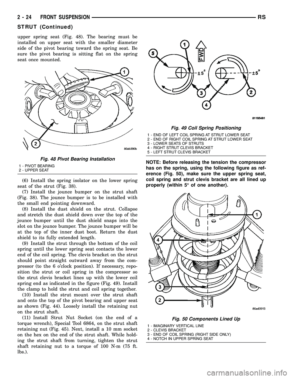
upper spring seat (Fig. 48). The bearing must be
installed on upper seat with the smaller diameter
side of the pivot bearing toward the spring seat. Be
sure the pivot bearing is sitting flat on the spring
seat once mounted.
(6) Install the spring isolator on the lower spring
seat of the strut (Fig. 38).
(7) Install the jounce bumper on the strut shaft
(Fig. 38). The jounce bumper is to be installed with
the small end pointing downward.
(8) Install the dust shield on the strut. Collapse
and stretch the dust shield down over the top of the
jounce bumper until the dust shield snaps into the
slot on the jounce bumper. The jounce bumper will be
at the top of the inner dust boot. Return the dust
shield to its fully extended length.
(9) Install the strut through the bottom of the coil
spring until the lower spring seat contacts the lower
end of the coil spring. The clevis bracket on the strut
should point straight outward away from the com-
pressor (to the 6 o'clock position). If necessary, repo-
sition the strut or coil spring in the compressor so
the strut clevis bracket lines up with the lower coil
spring end as indicated in the figure (Fig. 49). Install
the clamp to hold the strut and coil spring together.
(10) Install the strut mount over the strut shaft
and onto the top of the pivot bearing and upper seat
as shown (Fig. 44). Loosely install the retaining nut
on the strut shaft.
(11) Install Strut Nut Socket (on the end of a
torque wrench), Special Tool 6864, on the strut shaft
retaining nut (Fig. 45). Next, install a 10 mm socket
on the hex on the end of the strut shaft. While hold-
ing the strut shaft from turning, tighten the strut
shaft retaining nut to a torque of 100 N´m (75 ft.
lbs.).NOTE: Before releasing the tension the compressor
has on the spring, using the following figure as ref-
erence (Fig. 50), make sure the upper spring seat,
coil spring and strut clevis bracket are all lined up
properly (within 5É of one another).
Fig. 48 Pivot Bearing Installation
1 - PIVOT BEARING
2 - UPPER SEAT
Fig. 49 Coil Spring Positioning
1 - END OF LEFT COIL SPRING AT STRUT LOWER SEAT
2 - END OF RIGHT COIL SPRING AT STRUT LOWER SEAT
3 - LOWER SEATS OF STRUTS
4 - RIGHT STRUT CLEVIS BRACKET
5 - LEFT STRUT CLEVIS BRACKET
Fig. 50 Components Lined Up
1 - IMAGINARY VERTICAL LINE
2 - CLEVIS BRACKET
3 - END OF COIL SPRING (RIGHT SIDE ONLY)
4 - NOTCH IN UPPER SPRING SEAT
2 - 24 FRONT SUSPENSIONRS
STRUT (Continued)
Page 146 of 2339
MASTER CYLINDER
DESCRIPTION
DESCRIPTION
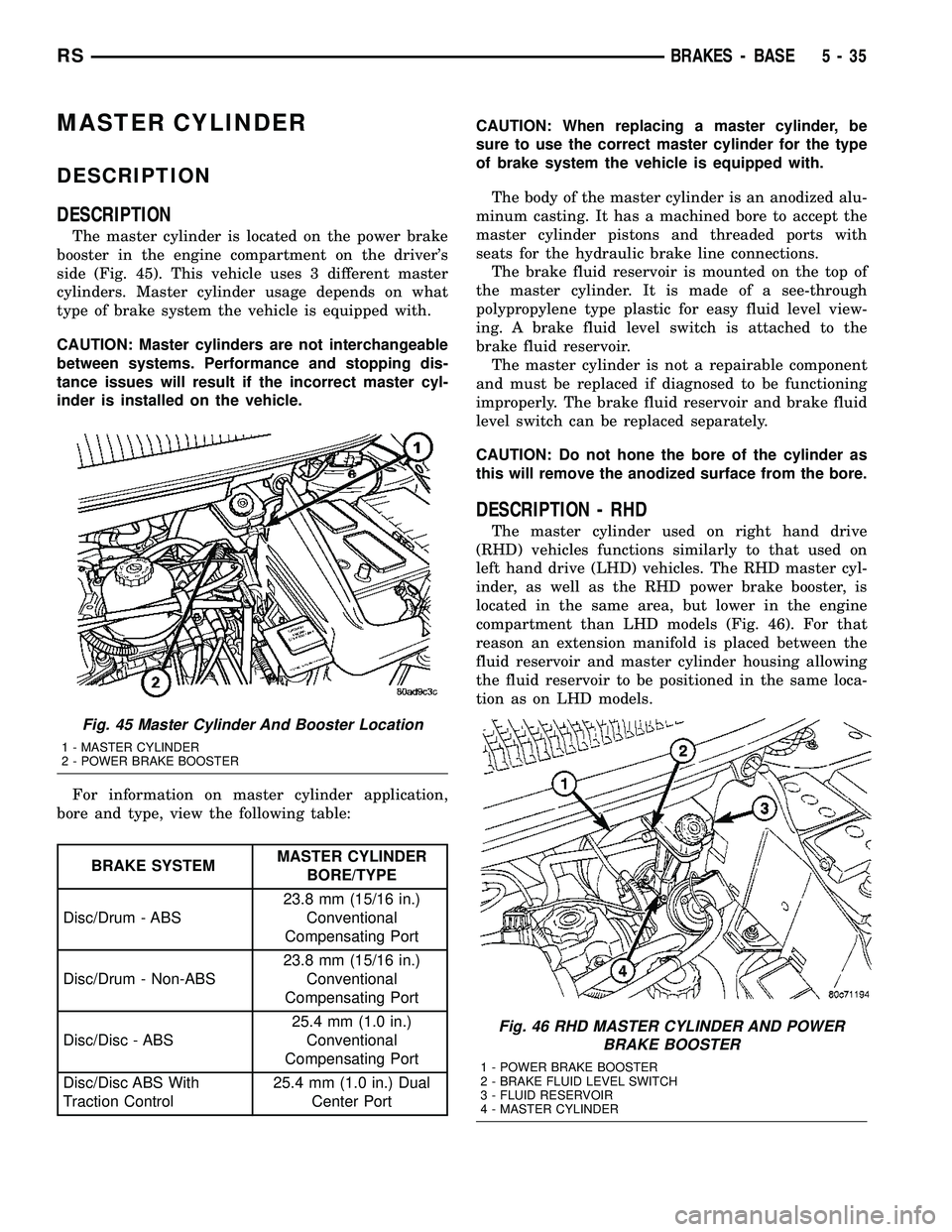
The master cylinder is located on the power brake
booster in the engine compartment on the driver's
side (Fig. 45). This vehicle uses 3 different master
cylinders. Master cylinder usage depends on what
type of brake system the vehicle is equipped with.
CAUTION: Master cylinders are not interchangeable
between systems. Performance and stopping dis-
tance issues will result if the incorrect master cyl-
inder is installed on the vehicle.
For information on master cylinder application,
bore and type, view the following table:
BRAKE SYSTEMMASTER CYLINDER
BORE/TYPE
Disc/Drum - ABS23.8 mm (15/16 in.)
Conventional
Compensating Port
Disc/Drum - Non-ABS23.8 mm (15/16 in.)
Conventional
Compensating Port
Disc/Disc - ABS25.4 mm (1.0 in.)
Conventional
Compensating Port
Disc/Disc ABS With
Traction Control25.4 mm (1.0 in.) Dual
Center PortCAUTION: When replacing a master cylinder, be
sure to use the correct master cylinder for the type
of brake system the vehicle is equipped with.
The body of the master cylinder is an anodized alu-
minum casting. It has a machined bore to accept the
master cylinder pistons and threaded ports with
seats for the hydraulic brake line connections.
The brake fluid reservoir is mounted on the top of
the master cylinder. It is made of a see-through
polypropylene type plastic for easy fluid level view-
ing. A brake fluid level switch is attached to the
brake fluid reservoir.
The master cylinder is not a repairable component
and must be replaced if diagnosed to be functioning
improperly. The brake fluid reservoir and brake fluid
level switch can be replaced separately.
CAUTION: Do not hone the bore of the cylinder as
this will remove the anodized surface from the bore.
DESCRIPTION - RHD
The master cylinder used on right hand drive
(RHD) vehicles functions similarly to that used on
left hand drive (LHD) vehicles. The RHD master cyl-
inder, as well as the RHD power brake booster, is
located in the same area, but lower in the engine
compartment than LHD models (Fig. 46). For that
reason an extension manifold is placed between the
fluid reservoir and master cylinder housing allowing
the fluid reservoir to be positioned in the same loca-
tion as on LHD models.
Fig. 45 Master Cylinder And Booster Location
1 - MASTER CYLINDER
2 - POWER BRAKE BOOSTER
Fig. 46 RHD MASTER CYLINDER AND POWER
BRAKE BOOSTER
1 - POWER BRAKE BOOSTER
2 - BRAKE FLUID LEVEL SWITCH
3 - FLUID RESERVOIR
4 - MASTER CYLINDER
RSBRAKES - BASE5-35
Page 174 of 2339
Vehicles with Fold-in-floor seating have three flex-
ible steel parking brake cables. They are:
²Front
²Left rear
²Right rear
The front parking brake cable extends from the
parking brake lever. A steel equalizer bracket con-
nects the front parking brake cable to the left rear
and intermediate cables on vehicles without Fold-in-
floor seating. The equalizer bracket connects the
front parking brake cable to the left rear and right
rear cables on vehicles with Fold-in-floor seating. The
intermediate cable is connected to the right rear
cable on vehicles without Fold-in-floor seating. A
standard cable connector is used to accomplish this
connection.
On vehicles equipped with rear drum brakes, the
rear service brakes also act as the vehicle's parking
brakes.
Vehicles equipped with rear disc brakes use a
small duo-servo brake assembly mounted to the each
rear disc brake caliper adapter as the parking brake.
The inside of the brake rotor (hat section of drum-in-
hat style brake rotor) is used as the parking brake
drum.
DESCRIPTION - EXPORT
The parking brake system on this vehicle features
a hand-operated parking brake lever. The lever is
located between the two front seats and requires a
special front cable.
OPERATION
The automatic-adjusting feature in the foot oper-
ated parking brake lever continuously applies mini-
mal tension to the parking brake cables when the
parking brake lever is in the released position to
keep them in adjustment at all times. Due to this
feature, the parking brake cables require no periodic
adjustment.
When the parking brake lever is applied, the
cables are pulled, thus applying the brake shoes
(rear drum brakes) or parking brake shoes (rear disc
brakes) at each rear wheel.
The brake shoes are mechanically operated by an
internal lever and strut connected to the rear park-
ing brake cables.
An equalizer bracket is used at the rear end of the
front parking brake cable to distribute tension
equally to each parking brake cable.
STANDARD PROCEDURE
STANDARD PROCEDURE - PARKING BRAKE
AUTOMATIC ADJUSTER TENSION RELEASE
The parking brake lever (pedal) mechanism used
in this vehicle is designed so that the automatic
adjuster is not required to be locked out when servic-
ing the parking brake lever (pedal) or the parking
brake cables.
This parking brake lever (pedal) mechanism is
designed so that the adjuster mechanism will rotate
only half a turn when the tension is released from
the parking brake cable. This eliminates the require-
ment to lock out the automatic adjuster when servic-
ing the parking brake lever (pedal) mechanism and
cables.
Use the following procedure to release the tension
from the parking brake cables and the automatic
adjuster in the parking brake lever (pedal) mecha-
nism.
(1) Release the parking brake.
(2) Raise and support the vehicle. (Refer to
LUBRICATION & MAINTENANCE/HOISTING -
STANDARD PROCEDURE)
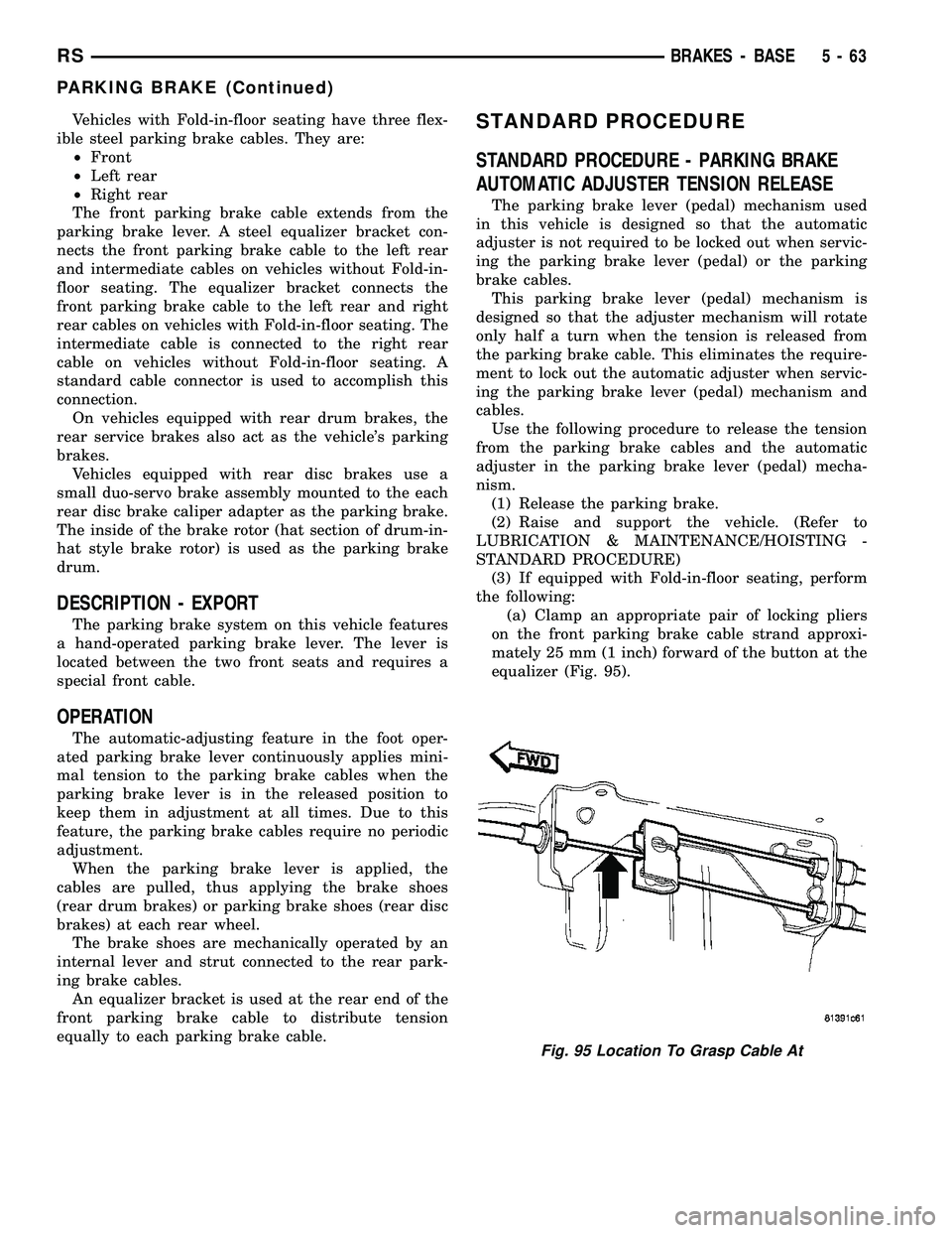
(3) If equipped with Fold-in-floor seating, perform
the following:
(a) Clamp an appropriate pair of locking pliers
on the front parking brake cable strand approxi-
mately 25 mm (1 inch) forward of the button at the
equalizer (Fig. 95).
Fig. 95 Location To Grasp Cable At
RSBRAKES - BASE5-63
PARKING BRAKE (Continued)
Page 293 of 2339
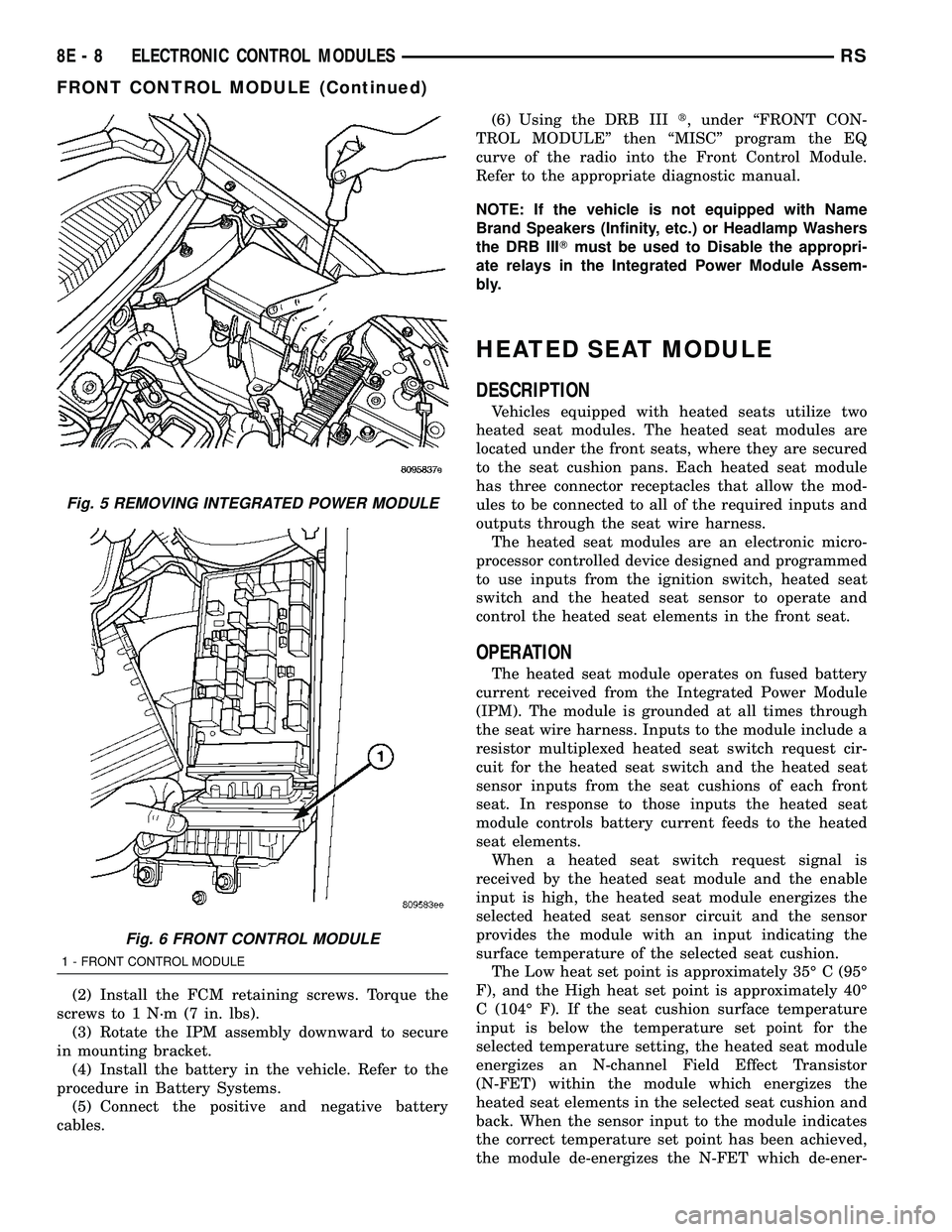
(2) Install the FCM retaining screws. Torque the
screws to 1 N´m (7 in. lbs).
(3) Rotate the IPM assembly downward to secure
in mounting bracket.
(4) Install the battery in the vehicle. Refer to the
procedure in Battery Systems.
(5) Connect the positive and negative battery
cables.(6) Using the DRB IIIt, under ªFRONT CON-
TROL MODULEº then ªMISCº program the EQ
curve of the radio into the Front Control Module.
Refer to the appropriate diagnostic manual.
NOTE: If the vehicle is not equipped with Name
Brand Speakers (Infinity, etc.) or Headlamp Washers
the DRB IIITmust be used to Disable the appropri-
ate relays in the Integrated Power Module Assem-
bly.
HEATED SEAT MODULE
DESCRIPTION
Vehicles equipped with heated seats utilize two
heated seat modules. The heated seat modules are
located under the front seats, where they are secured
to the seat cushion pans. Each heated seat module
has three connector receptacles that allow the mod-
ules to be connected to all of the required inputs and
outputs through the seat wire harness.
The heated seat modules are an electronic micro-
processor controlled device designed and programmed
to use inputs from the ignition switch, heated seat
switch and the heated seat sensor to operate and
control the heated seat elements in the front seat.
OPERATION
The heated seat module operates on fused battery
current received from the Integrated Power Module
(IPM). The module is grounded at all times through
the seat wire harness. Inputs to the module include a
resistor multiplexed heated seat switch request cir-
cuit for the heated seat switch and the heated seat
sensor inputs from the seat cushions of each front
seat. In response to those inputs the heated seat
module controls battery current feeds to the heated
seat elements.
When a heated seat switch request signal is
received by the heated seat module and the enable
input is high, the heated seat module energizes the
selected heated seat sensor circuit and the sensor
provides the module with an input indicating the
surface temperature of the selected seat cushion.
The Low heat set point is approximately 35É C (95É
F), and the High heat set point is approximately 40É
C (104É F). If the seat cushion surface temperature
input is below the temperature set point for the
selected temperature setting, the heated seat module
energizes an N-channel Field Effect Transistor
(N-FET) within the module which energizes the
heated seat elements in the selected seat cushion and
back. When the sensor input to the module indicates
the correct temperature set point has been achieved,
the module de-energizes the N-FET which de-ener-
Fig. 5 REMOVING INTEGRATED POWER MODULE
Fig. 6 FRONT CONTROL MODULE
1 - FRONT CONTROL MODULE
8E - 8 ELECTRONIC CONTROL MODULESRS
FRONT CONTROL MODULE (Continued)
Page 294 of 2339
gizes the heated seat elements. The heated seat mod-
ule will continue to cycle the N-FET as needed to
maintain the selected temperature set point.
DIAGNOSIS AND TESTING
HEATED SEAT MODULE
If a heated seat heats but one or both indicator
lamps on the heated seat switch fail to operate, test
the heated seat switch. (Refer to 8 - ELECTRICAL/
HEATED SEATS/DRIVER HEATED SEAT SWITCH
- DIAGNOSIS AND TESTING). If the heated seat
switch checks OK, proceed as follows.
(1) Check the heated seat element (Refer to 8 -
ELECTRICAL/HEATED SEATS/HEATED SEAT
ELEMENT - DIAGNOSIS AND TESTING).
(2) Check the heated seat sensor (Refer to 8 -
ELECTRICAL/HEATED SEATS/HEATED SEAT
SENSOR - DIAGNOSIS AND TESTING).
(3) Using a voltmeter, back probe the appropriate
heated seat module connector, do not disconnect.
Check for battery voltage at the appropriate pin cav-
ities. If OK go to Step 4. If not OK, repair the open
or shorted voltage supply circuit as required.
(4) Using a ohmmeter, back probe the appropriate
heated seat module connector, do not disconnect.
Check for proper continuity to ground on the ground
pin cavities. Continuity should be present. If OK
replace the heated seat module. If Not OK, repair the
open or shorted ground circuit as required.
REMOVAL
(1) Disconnect and isolate the negative battery
cable.
(2) Remove the appropriate front seat from the
vehicle (Refer to 23 - BODY/SEATS/SEAT -
REMOVAL).
(3) Unsnap the module from the seat cushion pan.
(4) Disconnect the module wire harness connec-
tors.
INSTALLATION
(1) Connect the module wire harness connectors.
(2) Snap the module on the seat cushion pan.
(3) Install the appropriate front seat in the vehicle
(Refer to 23 - BODY/SEATS/SEAT - INSTALLA-
TION).
(4) Connect and isolate the negative battery cable.
MEMORY SEAT/MIRROR
MODULE
DESCRIPTION
Vehicles equipped with the memory seat/mirror
option, utilize a memory module located under the
drivers front seat. This module is basically wired in-
line between the power seat switch and the power
seat track/adjuster motors, or in-line between the
power mirror switch and the power side view mir-
ror(s) motor(s). The Memory Seat/Mirror Module
(MSMM) contains a central processing unit that com-
municates with other modules on the Programmable
Communications Interface (PCI) data bus network.
The MSMM receives hard wired inputs from the
driver power seat switch and the potentiometers on
each of the driver side power seat track motors, or
from the power mirror switch and the potentiometers
on the side view mirror. The MSMM receives mes-
sages over the PCI data bus from the Body Control
Module (BCM) (memory switch status), the Power-
train Control Module (PCM) (vehicle speed status).
The MSMM will prevent the seat memory recall
function from being initiated if the driver side seat
belt is buckled, if the transmission gear selector lever
is not in the Park or Neutral positions, or if the vehi-
cle is moving.
For diagnosis of the MSMM or the PCI data bus, a
DRB IIItscan tool and the proper Diagnostic Proce-
dures Information are recommended. The MSMM
cannot be repaired and, if faulty or damaged, it must
be replaced.
OPERATION
When memory system operation is requested
(depressing of the memory switch), a resistor multi-
plexed signal is sent from the memory switch to the
Body Control Module (BCM). The BCM will then
send the appropriate signals out to the Memory Seat/
Mirror Module (MSMM), the MSMM then applies the
voltage supply to the power seat track or side-view
mirror if the proper requirements are met. The vehi-
cle speed must equal zero and the transmission must
be in park or neutral in order for the memory system
to function.
DIAGNOSIS AND TESTING
MEMORY SEAT/MIRROR MODULE
Any diagnosis of the Memory Seat/Mirror sys-
tem should begin with the use of the DRB IIIt
diagnostic tool. For information on the use of
the DRB IIIt, refer to the appropriate Diagnos-
tic Procedures information.
RSELECTRONIC CONTROL MODULES8E-9
HEATED SEAT MODULE (Continued)
Page 295 of 2339
Inspect the related wiring harness connectors for
broken, bent, pushed out, or corroded terminals.
Refer to the appropriate wiring information.
REMOVAL
(1) Disconnect and isolate the battery negative
cable.
(2) Remove the driver side front bucket seat
retaining nuts from under the vehicle (Refer to 23 -
BODY/SEATS/SEAT - REMOVAL).
(3) Lift the drivers seat up and out of the mount-
ing holes in the floor pan and lay the seat rearward
to access the module located under the seat.
(4) Disconnect the memory seat/mirror module
electrical connectors. Depress the retaining tab and
pull straight apart.
(5) Remove the module retaining bolts and remove
the module from the bracket.
INSTALLATION
(1) Position and install the module retaining bolts.
(2) Connect the memory seat/mirror module elec-
trical connectors.
(3) Position the drivers seat in the mounting holes
in the floor pan.
(4) Install the driver side front bucket seat retain-
ing nuts from under the vehicle (Refer to 23 - BODY/
SEATS/SEAT - INSTALLATION).
(5) Connect the battery negative cable.
POWER LIFTGATE CONTROL
MODULE
DESCRIPTION
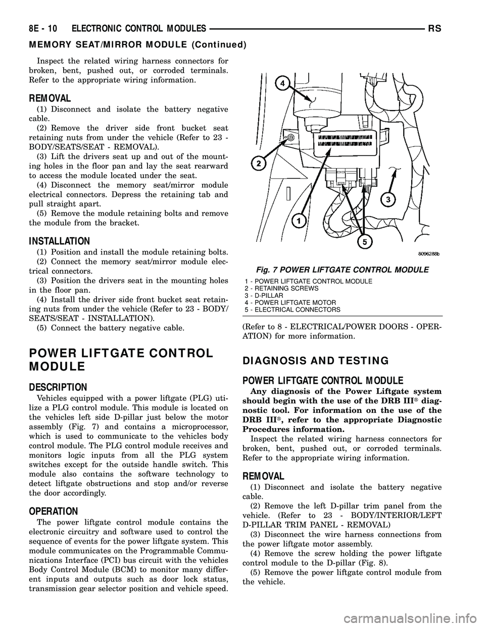
Vehicles equipped with a power liftgate (PLG) uti-
lize a PLG control module. This module is located on
the vehicles left side D-pillar just below the motor
assembly (Fig. 7) and contains a microprocessor,
which is used to communicate to the vehicles body
control module. The PLG control module receives and
monitors logic inputs from all the PLG system
switches except for the outside handle switch. This
module also contains the software technology to
detect liftgate obstructions and stop and/or reverse
the door accordingly.
OPERATION
The power liftgate control module contains the
electronic circuitry and software used to control the
sequence of events for the power liftgate system. This
module communicates on the Programmable Commu-
nications Interface (PCI) bus circuit with the vehicles
Body Control Module (BCM) to monitor many differ-
ent inputs and outputs such as door lock status,
transmission gear selector position and vehicle speed.(Refer to 8 - ELECTRICAL/POWER DOORS - OPER-
ATION) for more information.
DIAGNOSIS AND TESTING
POWER LIFTGATE CONTROL MODULE
Any diagnosis of the Power Liftgate system
should begin with the use of the DRB IIItdiag-
nostic tool. For information on the use of the
DRB IIIt, refer to the appropriate Diagnostic
Procedures information.
Inspect the related wiring harness connectors for
broken, bent, pushed out, or corroded terminals.
Refer to the appropriate wiring information.
REMOVAL
(1) Disconnect and isolate the battery negative
cable.
(2) Remove the left D-pillar trim panel from the
vehicle. (Refer to 23 - BODY/INTERIOR/LEFT
D-PILLAR TRIM PANEL - REMOVAL)
(3) Disconnect the wire harness connections from
the power liftgate motor assembly.
(4) Remove the screw holding the power liftgate
control module to the D-pillar (Fig. 8).
(5) Remove the power liftgate control module from
the vehicle.
Fig. 7 POWER LIFTGATE CONTROL MODULE
1 - POWER LIFTGATE CONTROL MODULE
2 - RETAINING SCREWS
3 - D-PILLAR
4 - POWER LIFTGATE MOTOR
5 - ELECTRICAL CONNECTORS
8E - 10 ELECTRONIC CONTROL MODULESRS
MEMORY SEAT/MIRROR MODULE (Continued)
Page 352 of 2339
HEATED SEAT SYSTEM
TABLE OF CONTENTS
page page
HEATED SEAT SYSTEM
DESCRIPTION..........................7
OPERATION............................8
DIAGNOSIS AND TESTING
HEATED SEAT SYSTEM.................8
HEATED SEAT SWITCH
DESCRIPTION..........................8
OPERATION............................9
DIAGNOSIS AND TESTING
DRIVER HEATED SEAT SWITCH..........9
REMOVAL.............................10
INSTALLATION.........................10HEATED SEAT ELEMENTS
DESCRIPTION.........................11
OPERATION...........................11
DIAGNOSIS AND TESTING
HEATED SEAT ELEMENTS..............11
REMOVAL.............................12
INSTALLATION.........................12
HEATED SEAT SENSOR
DESCRIPTION.........................13
OPERATION...........................13
DIAGNOSIS AND TESTING
HEATED SEAT SENSOR................13
HEATED SEAT SYSTEM
DESCRIPTION
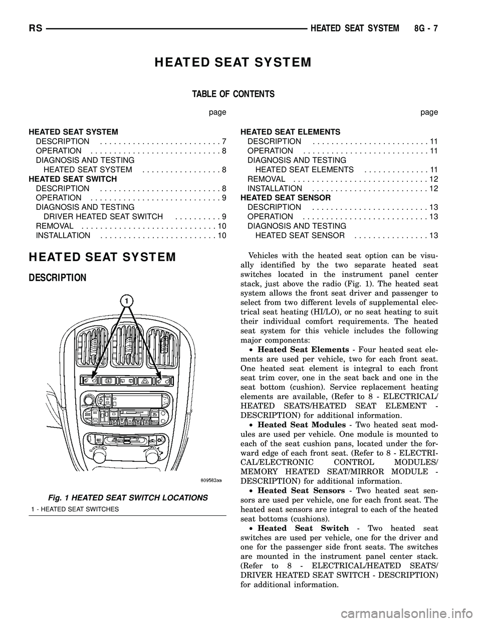
Vehicles with the heated seat option can be visu-
ally identified by the two separate heated seat
switches located in the instrument panel center
stack, just above the radio (Fig. 1). The heated seat
system allows the front seat driver and passenger to
select from two different levels of supplemental elec-
trical seat heating (HI/LO), or no seat heating to suit
their individual comfort requirements. The heated
seat system for this vehicle includes the following
major components:
²Heated Seat Elements- Four heated seat ele-
ments are used per vehicle, two for each front seat.
One heated seat element is integral to each front
seat trim cover, one in the seat back and one in the
seat bottom (cushion). Service replacement heating
elements are available, (Refer to 8 - ELECTRICAL/
HEATED SEATS/HEATED SEAT ELEMENT -
DESCRIPTION) for additional information.
²Heated Seat Modules- Two heated seat mod-
ules are used per vehicle. One module is mounted to
each of the seat cushion pans, located under the for-
ward edge of each front seat. (Refer to 8 - ELECTRI-
CAL/ELECTRONIC CONTROL MODULES/
MEMORY HEATED SEAT/MIRROR MODULE -
DESCRIPTION) for additional information.
²Heated Seat Sensors- Two heated seat sen-
sors are used per vehicle, one for each front seat. The
heated seat sensors are integral to each of the heated
seat bottoms (cushions).
²Heated Seat Switch- Two heated seat
switches are used per vehicle, one for the driver and
one for the passenger side front seats. The switches
are mounted in the instrument panel center stack.
(Refer to 8 - ELECTRICAL/HEATED SEATS/
DRIVER HEATED SEAT SWITCH - DESCRIPTION)
for additional information.
Fig. 1 HEATED SEAT SWITCH LOCATIONS
1 - HEATED SEAT SWITCHES
RSHEATED SEAT SYSTEM8G-7
Page 353 of 2339

Hard wired circuitry connects the heated seat sys-
tem components to each other through the electrical
system of the vehicle. These circuits may be con-
nected to each other, to the vehicle electrical system
and to the heated seat system components through
the use of a combination of soldered splices and
splice block connectors. Refer to the appropriate wir-
ing information for complete circuit schematic or con-
nector pin-out information.
OPERATION
The heated seat system components operate on
battery current received through a fuse in the Inte-
grated Power Module (IPM) on a fused ignition
switch output (run) circuit from the Body Control
Module (BCM). The system will only operate when
the ignition switch is in the On position. The heated
seat system will be turned Off automatically when-
ever the ignition switch is turned to any position
except On. Also, the heated seat system will not oper-
ate when the surface temperature of the seat cushion
cover at either heated seat sensor is above the
designed temperature set points of the system.
DIAGNOSIS AND TESTING
HEATED SEAT SYSTEM
The most efficient means of diagnosing the heated
seat system is by individual component. For diagno-
sis of a specific component refer to the following:
²Heated seat module, (Refer to 8 - ELECTRICAL/
ELECTRONIC CONTROL MODULES/MEMORY
HEATED SEAT/MIRROR MODULE - DIAGNOSIS
AND TESTING).
²Heated seat elements, (Refer to 8 - ELECTRI-
CAL/HEATED SEATS/HEATED SEAT ELEMENT -
DIAGNOSIS AND TESTING).
²Heated seat switch, (Refer to 8 - ELECTRICAL/
HEATED SEATS/DRIVER HEATED SEAT SWITCH
- DIAGNOSIS AND TESTING).
²Heated seat sensor, (Refer to 8 - ELECTRICAL/
HEATED SEATS/HEATED SEAT SENSOR - DIAG-
NOSIS AND TESTING).
Refer to the appropriate wiring information for
complete circuit schematic or connector pin-out infor-
mation.
HEATED SEAT SWITCH
DESCRIPTION
The heated seat switches are mounted in the
instrument panel center bezel (Fig. 2). The two three-
position rocker-type switches, one switch for each
front seat, are incorporated into one large switch
assembly that also includes the hazard, rear window
wiper and washer switches. Each heated seat switch
provides a resistor multiplexed signal to its respec-
tive Heated Seat Module (HSM) through separate
hard wired circuits. Each switch has an Off, Low,
and High position so that both the driver and the
front seat passenger can select a preferred seat heat-
ing mode. Each switch has two Light-Emitting
Diodes (LED) which light to indicate that the heater
for the seat is turned on.
The heated seat switches and their LEDs cannot
be repaired. If either switch or LED is faulty or dam-
aged, the entire switch assembly must be replaced.
Fig. 2 HEATED SEAT SWITCH LOCATION
1 - HEATED SEAT SWITCHES
8G - 8 HEATED SEAT SYSTEMRS
HEATED SEAT SYSTEM (Continued)
Page 356 of 2339
(3) Install the center bezel onto the instrument
panel, (Refer to 23 - BODY/INSTRUMENT PANEL/
INSTRUMENT PANEL CENTER BEZEL - INSTAL-
LATION).
(4) Connect the battery negative cable.
HEATED SEAT ELEMENTS
DESCRIPTION
The heated seat system includes two seat heating
elements in each front seat, one for the seat cushion
and the other for the seat back. The two elements for
each seat that are connected in series with the
Heated Seat Module (HSM). The temperature sensor
is a Negative Temperature Coefficient (NTC) ther-
mistor. One temperature sensor is used for each seat,
and it is located on the seat cushion heating element
for all models.
The seat heating elements are attached to the seat
cushion cover trim and seat back cover trim units.
The heated seat elements and the temperature sen-
sor cannot be adjusted or repaired and, if faulty or
damaged, the seat element assembly must be
replaced, (Refer to 8 - ELECTRICAL/HEATED
SEATS/HEATED SEAT ELEMENT - REMOVAL).
OPERATION
The heated seat elements resist the flow of electri-
cal current. When battery current is passed through
the elements, the resistance of the elements to the
current flow is released in the form of heat. The tem-
perature sensor is a Negative Temperature Coeffi-
cient (NTC) thermistor. When the temperature of the
seat cushion cover rises, the resistance of the sensor
decreases. The heated seat module supplies a five-
volt signal to one side of each sensor, and monitors
the voltage drop through the sensor on a return cir-
cuit. The heated seat module uses this temperature
sensor input to monitor the temperature of the seat,
and regulates the current flow to the seat heating
elements accordingly.
DIAGNOSIS AND TESTING
HEATED SEAT ELEMENTS
The wire harness connectors for the seat cushion
and seat back heating elements are located under the
seat, at the heated seat module. Refer to the appro-
priate wiring information for complete circuit sche-
matic or connector pin-out information.
In order to access and test the heated seat ele-
ments it will be necessary to remove the appropriate
front seat retaining bolts and lay the seat rearward,
up against one of the rear seats. It is not necessary
to disconnect the seat electrical connectors, just use
care not to damage the attached wire harnesses
while testing.
NOTE: When checking heated seat elements for
continuity, be certain to move the heating element
being checked. Moving the element, such as sitting
in the seat will eliminate the possibility of an inter-
mittent open in the element which would only be
evident if the element was in a certain position.
Failure to check the element in various positions
could result in an incomplete test.
SEAT CUSHION ELEMENT
(1) From under the vehicle, remove the appropri-
ate seats four retaining nuts.
(2) From inside the vehicle, pull the seat up, off
the mounting studs and lay it back, up against one of
the rear seats.
(3) Locate the heated seat module, attached to the
bottom of the seat cushion pan. Remove the heated
seat module from the seat cushion pan. Do not dis-
connect the electrical connectors at this time.
(4) Locate and disconnect the green 4-way electri-
cal connector, connected to the heated seat module.
(5) Check for continuity between the two outboard
circuit cavities of the wire harness connector (Pins
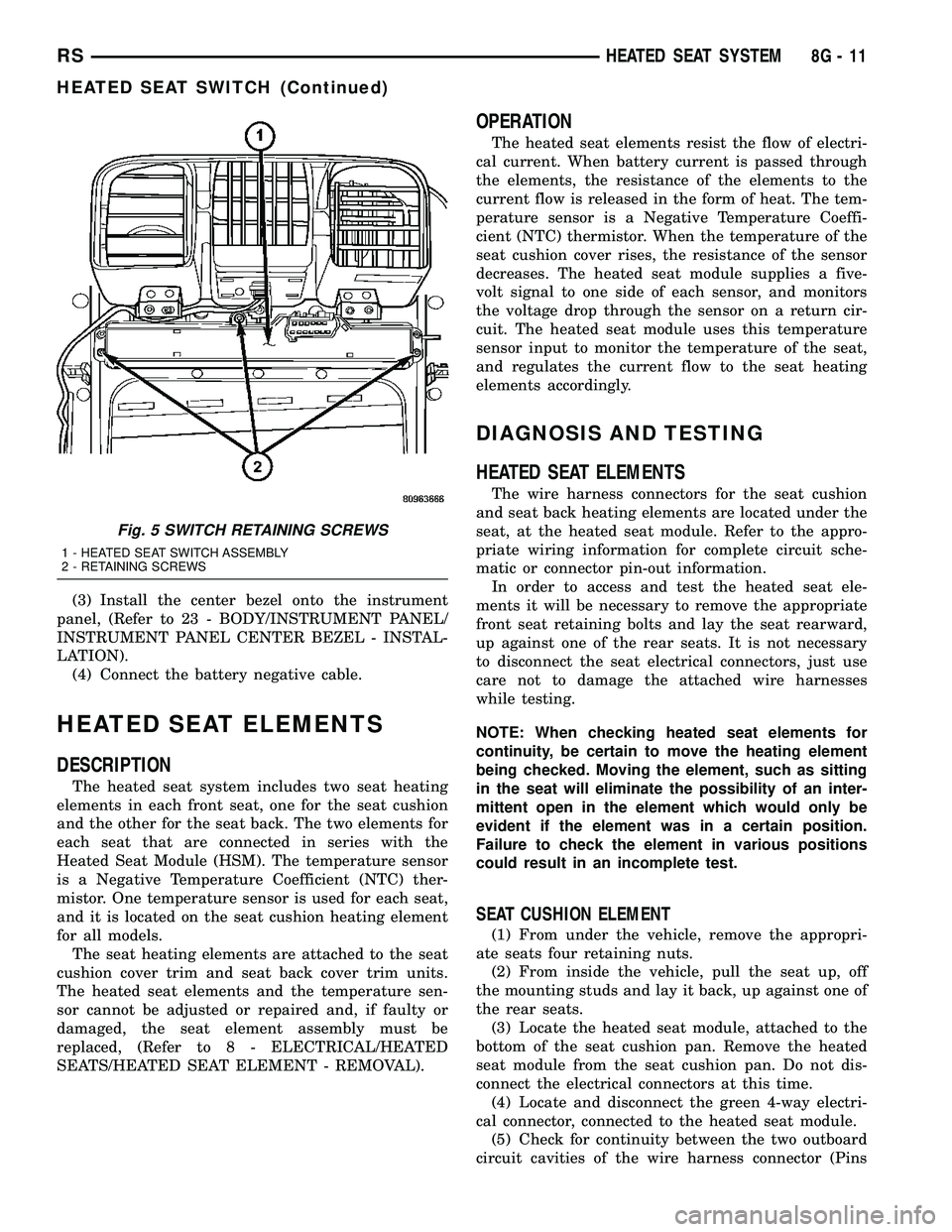
Fig. 5 SWITCH RETAINING SCREWS
1 - HEATED SEAT SWITCH ASSEMBLY
2 - RETAINING SCREWS
RSHEATED SEAT SYSTEM8G-11
HEATED SEAT SWITCH (Continued)
Page 357 of 2339
1&4). There should be continuity. If OK, (Refer to 8 -
ELECTRICAL/ELECTRONIC CONTROL MOD-
ULES/MEMORY HEATED SEAT/MIRROR MOD-
ULE - DIAGNOSIS AND TESTING) for complete
system testing procedures. If not OK, install a
replacement heated seat cushion element, (Refer to 8
- ELECTRICAL/HEATED SEATS/HEATED SEAT
ELEMENT - INSTALLATION).
SEAT BACK ELEMENT
(1) From under the vehicle, remove the appropri-
ate seats four retaining nuts.
(2) From inside the vehicle, pull the seat up and
off the mounting studs and lay it back, up against
one of the rear seats.
(3) Locate the heated seat module, attached to the
bottom of the seat cushion pan. Remove the heated
seat module from the seat cushion pan. Do not dis-
connect the electrical connectors at this time.
(4) Locate and disconnect the gray 2-way electrical
connector, connected to the heated seat module.
(5) Check for continuity between the two circuit
cavities of the 2-way wire harness connector. There
should be continuity. If OK, (Refer to 8 - ELECTRI-
CAL/ELECTRONIC CONTROL MODULES/MEM-
ORY HEATED SEAT/MIRROR MODULE -
DIAGNOSIS AND TESTING) for complete system
testing procedures. If not OK, install a replacement
heated seat back element, (Refer to 8 - ELECTRI-
CAL/HEATED SEATS/HEATED SEAT ELEMENT -
INSTALLATION).
REMOVAL
NOTE: Do not remove the factory installed heating
elements from the seat or seat back cushions. The
original element is permanently attached and can-
not be removed without permanent damage. The
replacement heating element is designed to be
applied directly on top of the factory installed heat-
ing element.
(1) Disconnect and isolate the battery negative
cable.
(2) Remove the appropriate seat cushion or seat
back trim cover.
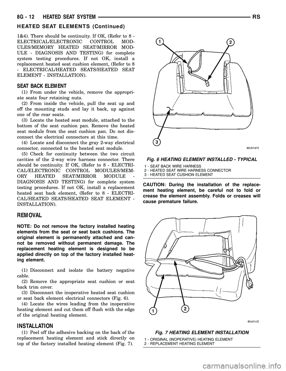
(3) Disconnect the inoperative heated seat cushion
or seat back element electrical connectors (Fig. 6).
(4) Locate the wires leading from the inoperative
heating element and cut them off flush with the edge
of the original heating element.
INSTALLATION
(1) Peel off the adhesive backing on the back of the
replacement heating element and stick directly on
top of the factory installed heating element (Fig. 7).CAUTION: During the installation of the replace-
ment heating element, be careful not to fold or
crease the element assembly. Folds or creases will
cause premature failure.
Fig. 6 HEATING ELEMENT INSTALLED - TYPICAL
1 - SEAT BACK WIRE HARNESS
2 - HEATED SEAT WIRE HARNESS CONNECTOR
3 - HEATED SEAT CUSHION ELEMENT
Fig. 7 HEATING ELEMENT INSTALLATION
1 - ORIGINAL (INOPERATIVE) HEATING ELEMENT
2 - REPLACEMENT HEATING ELEMENT
8G - 12 HEATED SEAT SYSTEMRS
HEATED SEAT ELEMENTS (Continued)