washer fluid CHRYSLER VOYAGER 2005 Service Manual
[x] Cancel search | Manufacturer: CHRYSLER, Model Year: 2005, Model line: VOYAGER, Model: CHRYSLER VOYAGER 2005Pages: 2339, PDF Size: 59.69 MB
Page 20 of 2339
FLUID FILL/CHECK
LOCATIONS
DESCRIPTION
The fluid check/fill point locations are located in
each applicable service manual section.
LUBRICATION POINTS
DESCRIPTION
Lubrication point locations are located in each
applicable Sections.
MAINTENANCE SCHEDULES
DESCRIPTION
DESCRIPTION
There are two maintenance schedules that show
therequiredservice for your vehicle.
First is ScheduleªBº. It is for vehicles that are
operated under the conditions that are listed below
and at the beginning of the schedule.
²Day or night temperatures are below 32É F (0É
C).
²Stop and go driving.
²Extensive engine idling.
²Driving in dusty conditions.
²Short trips of less than 10 miles (16 km).
²More than 50% of your driving is at sustained
high speeds during hot weather, above 90É F (32É C).
²Trailer towing.L
²Taxi, police, or delivery service (commercial ser-
vice).L
²Off-road or desert operation.
NOTE: Most vehicles are operated under the condi-
tions listed for Schedule(B(.
Second is ScheduleªAº. It is for vehicles that are
not operated under any of the conditions listed under
Schedule9B9.
Use the schedule that best describes your driving
conditions. Where time and mileage are listed, follow
the interval that occurs first.
CAUTION: Failure to perform the required mainte-
nance items may result in damage to the vehicle.
At Each Stop for Fuel
²Check the engine oil level about 5 minutes after
a fully warmed engine is shut off. Checking the oil
level while the vehicle is on level ground will
improve the accuracy of the oil level reading. Add oil
only when the level is at or below the ADD or MIN
mark.
²Check the windshield washer solvent and add if
required.
Once a Month
²Check tire pressure and look for unusual wear
or damage.
²Inspect the battery and clean and tighten the
terminals as required.
²Check the fluid levels of coolant reservoir, brake
master cylinder and transmission, add as needed.
²Check all lights and all other electrical items for
correct operation.
At Each Oil Change
²Change the engine oil filter.
²Inspect the exhaust system.
²Inspect the brake hoses.
²Inspect the CV joints and front suspension com-
ponents.
²Check the automatic transmission fluid level.
²Check the coolant level, hoses, and clamps.
SCHEDULE B
Follow schedule ªBº if you usually operate your
vehicle under one or more of the following conditions.
Change the automatic transmission fluid and filter
every 60,000 miles (96 000 km) if the vehicle is usu-
ally operated under one or more of the conditions
marked with anL.
²Day or night temperatures are below 32É F (0É
C).
²Stop and go driving.
²Extensive engine idling.
²Driving in dusty conditions.
²Short trips of less than 10 miles (16 km).
²More than 50% of your driving is at sustained
high speeds during hot weather, above 90É F (32É C).
²Trailer towing.L
²Taxi, police, or delivery service (commercial ser-
vice).L
²Off-road or desert operation.
RSLUBRICATION & MAINTENANCE0-7
Page 26 of 2339
DESCRIPTION - EXPORT
There are two maintenance schedules that show
therequiredservice for your vehicle.
First is ScheduleªAº. It is for vehicles that are not
operated under any of the conditions listed under
Schedule9B9.
Second is ScheduleªBº. It is for vehicles that are
operated under the conditions that are listed below
and at the beginning of the schedule.
²Day or night temperatures are below 0É C (32É
F).
²Stop and go driving.
²Extensive engine idling.
²Driving in dusty conditions.
²Short trips of less than 16 km (10 miles).
²More than 50% of your driving is at sustained
high speeds during hot weather, above 32É C (90É F).
²Trailer towing.L
²Taxi, police, or delivery service (commercial ser-
vice).L
²Off-road or desert operation.
NOTE: Most vehicles are operated under the condi-
tions listed for Schedule(B(.
Use the schedule that best describes your driving
conditions. Where time and mileage are listed, follow
the interval that occurs first.
CAUTION: Failure to perform the required mainte-
nance items may result in damage to the vehicle.
At Each Stop for Fuel
²Check the engine oil level about 5 minutes after
a fully warmed engine is shut off. Checking the oil
level while the vehicle is on level ground will
improve the accuracy of the oil level reading. Add oil
only when the level is at or below the ADD or MIN
mark.
²Check the windshield washer solvent and add if
required.
Once a Month
²Check tire pressure and look for unusual wear
or damage.
²Inspect the battery and clean and tighten the
terminals as required.
²Check the fluid levels of coolant reservoir, brake
master cylinder and transmission, add as needed.
²Check all lights and all other electrical items for
correct operation.
At Each Oil Change
²Change the engine oil filter.
²Inspect the exhaust system.
²Inspect the brake hoses.
²Inspect the CV joints and front suspension com-
ponents.
²Check the automatic transmission fluid level.
²Check the manual transmission fluid level.
²Check the coolant level, hoses, and clamps.
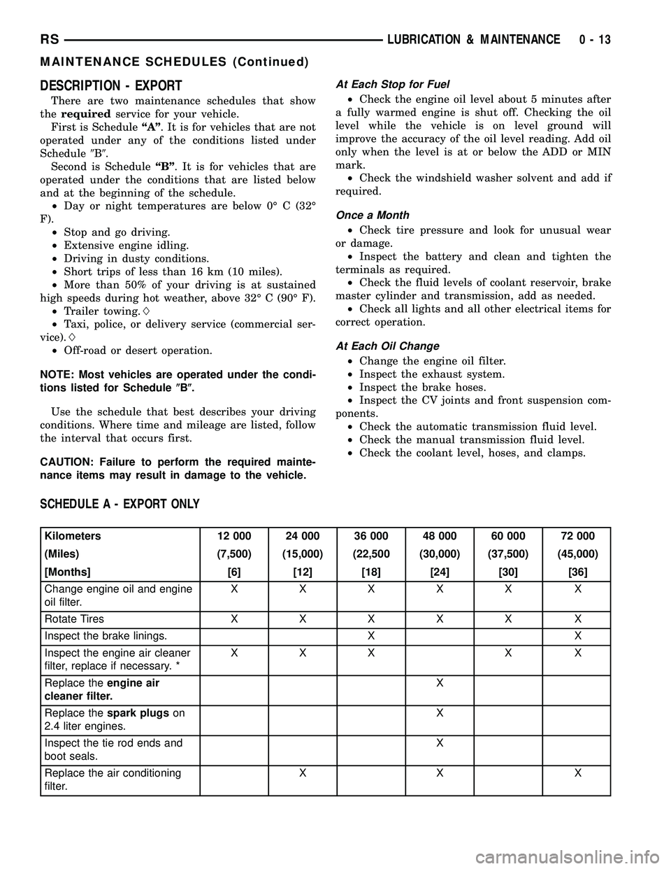
SCHEDULE A - EXPORT ONLY
Kilometers 12 000 24 000 36 000 48 000 60 000 72 000
(Miles) (7,500) (15,000) (22,500 (30,000) (37,500) (45,000)
[Months] [6] [12] [18] [24] [30] [36]
Change engine oil and engine
oil filter.XXXXX X
Rotate Tires XXXXX X
Inspect the brake linings. X X
Inspect the engine air cleaner
filter, replace if necessary. *XXX X X
Replace theengine air
cleaner filter.X
Replace thespark plugson
2.4 liter engines.X
Inspect the tie rod ends and
boot seals.X
Replace the air conditioning
filter.XX X
RSLUBRICATION & MAINTENANCE0-13
MAINTENANCE SCHEDULES (Continued)
Page 34 of 2339
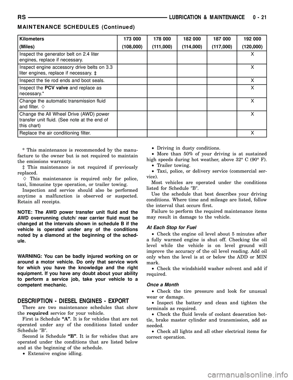
Kilometers 173 000 178 000 182 000 187 000 192 000
(Miles) (108,000) (111,000) (114,000) (117,000) (120,000)
Inspect the generator belt on 2.4 liter
engines, replace if necessary.X
Inspect engine accessory drive belts on 3.3
liter engines, replace if necessary. ³X
Inspect the tie rod ends and boot seals. X
Inspect thePCV valveand replace as
necessary.*X
Change the automatic transmission fluid
and filter.LX
Change the All Wheel Drive (AWD) power
transfer unit fluid. (See note at the end of
this chart)X
Replace the air conditioning filter.X
* This maintenance is recommended by the manu-
facture to the owner but is not required to maintain
the emissions warranty.
³ This maintenance is not required if previously
replaced.
LThis maintenance is required only for police,
taxi, limousine type operation, or trailer towing.
Inspection and service should also be performed
anytime a malfunction is observed or suspected.
Retain all receipts.
NOTE: The AWD power transfer unit fluid and the
AWD overrunning clutch/ rear carrier fluid must be
changed at the intervals shown in schedule B if the
vehicle is operated under any of the conditions
noted by a diamond at the beginning of the sched-
ule.
WARNING: You can be badly injured working on or
around a motor vehicle. Do only that service work
for which you have the knowledge and the right
equipment. If you have any doubt about your ability
to perform a service job, take your vehicle to a
competent mechanic.
DESCRIPTION - DIESEL ENGINES - EXPORT
There are two maintenance schedules that show
therequiredservice for your vehicle.
First is ScheduleªAº. It is for vehicles that are not
operated under any of the conditions listed under
Schedule9B9.
Second is ScheduleªBº. It is for vehicles that are
operated under the conditions that are listed below
and at the beginning of the schedule.
²Extensive engine idling.²Driving in dusty conditions.
²More than 50% of your driving is at sustained
high speeds during hot weather, above 32É C (90É F).
²Trailer towing.
²Taxi, police, or delivery service (commercial ser-
vice).
Most vehicles are operated under the conditions
listed for Schedule9B9.
Use the schedule that best describes your driving
conditions. Where time and mileage are listed, follow
the interval that occurs first.
Failure to perform the required maintenance items
may result in damage to the vehicle.
At Each Stop for Fuel
²Check the engine oil level about 5 minutes after
a fully warmed engine is shut off. Checking the oil
level while the vehicle is on level ground will
improve the accuracy of the oil level reading. Add oil
only when the level is at or below the ADD or MIN
mark.
²Check the windshield washer solvent and add if
required.
Once a Month
²Check the tire pressure and look for unusual
wear or damage.
²Inspect the battery and clean and tighten the
terminals as required.
²Check the fluid levels of coolant deaeration bot-
tle, brake master cylinder and transmission, add as
needed.
²Check all lights and all other electrical items for
correct operation.
RSLUBRICATION & MAINTENANCE0-21
MAINTENANCE SCHEDULES (Continued)
Page 102 of 2339
(6) Slide half shaft back into front hub and bear-
ing assembly.
CAUTION: The steering knuckle to strut assembly
attaching bolts are serrated and must not be turned
during installation. Install nuts while holding bolts
stationary in the steering knuckle.
CAUTION: If the vehicle being serviced is equipped
with eccentric strut assembly attaching bolts, the
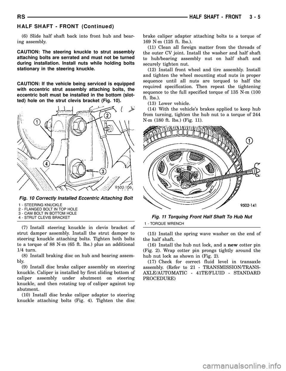
eccentric bolt must be installed in the bottom (slot-
ted) hole on the strut clevis bracket (Fig. 10).
(7) Install steering knuckle in clevis bracket of
strut damper assembly. Install the strut damper to
steering knuckle attaching bolts. Tighten both bolts
to a torque of 88 N´m (65 ft. lbs.) plus an additional
1/4 turn.
(8) Install braking disc on hub and bearing assem-
bly.
(9) Install disc brake caliper assembly on steering
knuckle. Caliper is installed by first sliding bottom of
caliper assembly under abutment on steering
knuckle, and then rotating top of caliper against top
abutment.
(10) Install disc brake caliper adapter to steering
knuckle attaching bolts (Fig. 4). Tighten the discbrake caliper adapter attaching bolts to a torque of
169 N´m (125 ft. lbs.).
(11) Clean all foreign matter from the threads of
the outer CV joint. Install the washer and half shaft
to hub/bearing assembly nut on half shaft and
securely tighten nut.
(12) Install front wheel and tire assembly. Install
and tighten the wheel mounting stud nuts in proper
sequence until all nuts are torqued to half the
required specification. Then repeat the tightening
sequence to the full specified torque of 135 N´m (100
ft. lbs.).
(13) Lower vehicle.
(14) With the vehicle's brakes applied to keep hub
from turning, tighten the hub nut to a torque of 244
N´m (180 ft. lbs.) (Fig. 11).
(15) Install the spring wave washer on the end of
the half shaft.
(16) Install the hub nut lock, and anewcotter pin
(Fig. 2). Wrap cotter pin prongs tightly around the
hub nut lock as shown in (Fig. 2).
(17) Check for correct fluid level in transaxle
assembly. (Refer to 21 - TRANSMISSION/TRANS-
AXLE/AUTOMATIC - 41TE/FLUID - STANDARD
PROCEDURE)
Fig. 10 Correctly Installed Eccentric Attaching Bolt
1 - STEERING KNUCKLE
2 - FLANGED BOLT IN TOP HOLE
3 - CAM BOLT IN BOTTOM HOLE
4 - STRUT CLEVIS BRACKET
Fig. 11 Torquing Front Half Shaft To Hub Nut
1 - TORQUE WRENCH
RSHALF SHAFT - FRONT3-5
HALF SHAFT - FRONT (Continued)
Page 135 of 2339

DISC BRAKE CALIPER -
FRONT
REMOVAL
REMOVAL - FRONT DISC BRAKE CALIPER
(CONTINENTAL TEVES BRAKES)
(1) Depress the brake pedal past its first inch of
travel and hold it in this position using a brake pedal
depressor (holding) tool. This is done to isolate the
master cylinder from the brake hydraulic system dis-
allowing the brake fluid to completely drain out of
the brake fluid reservoir.
(2) Raise the vehicle. (Refer to LUBRICATION &
MAINTENANCE/HOISTING - STANDARD PROCE-
DURE).
(3) Remove front wheel and tire assembly.
(4) Remove the banjo bolt connecting the brake
hose to the brake caliper. There are two washers (one
on each side of the brake hose fitting) that will come
off with the banjo bolt. Discard these washers.
(5) Remove the 2 caliper guide pin bolts.
(6) Remove the brake caliper from the adapter.
REMOVAL - FRONT DISC BRAKE CALIPER
(TRW BRAKES)
(1) Using a brake pedal holding tool, depress the
brake pedal past its first one inch of travel and hold
it in this position. This will isolate the master cylin-
der from the brake hydraulic system and will not
allow the brake fluid to drain out of the master cyl-
inder reservoir when the lines are opened.
(2) Raise the vehicle. Refer to HOISTING in
LUBRICATION AND MAINTENANCE.
(3) Remove the front tire and wheel assembly.
(4) Remove the banjo bolt connecting the brake
hose to the brake caliper (Fig. 31). There are two
washers (one on each side of the flex hose fitting)
that will come off with the banjo bolt. Discard the
washers.
(5) Remove the two brake caliper guide pin bolts
(Fig. 31).
(6) Remove the disc brake caliper from the disc
brake adapter.
DISASSEMBLY
DISASSEMBLY - CALIPER GUIDE PIN
BUSHINGS (CONTINENTAL TEVES BRAKES)
Before disassembling the brake caliper, clean and
inspect it. Refer to CLEANING or INSPECTION in
this section.(1) Using your fingers, collapse one side of the rub-
ber guide pin bushing. Pull the guide pin bushing out
the other side of the brake caliper mounting boss.
(2) Repeat this procedure on the remaining bush-
ing.
DISASSEMBLY - CALIPER PISTON AND SEAL
WARNING: UNDER NO CONDITION SHOULD HIGH
PRESSURE AIR EVER BE USED TO REMOVE A PIS-
TON FROM A CALIPER BORE. PERSONAL INJURY
COULD RESULT FROM SUCH A PRACTICE.
NOTE: Before disassembling the brake caliper,
clean and inspect it. Refer to CLEANING AND
INSPECTION in this section.
NOTE: The safest way to remove the piston from
the caliper bore is to use the hydraulic pressure of
the vehicle's brake system.
(1) Following the removal procedure in DISC
BRAKE SHOES found in this section, remove the
caliper from the brake rotor and hang the assembly
on a wire hook away from rotor and body of the vehi-
cle so brake fluid cannot get on these components.
Remove the brake shoes, and place a small piece of
wood between the piston and caliper fingers.
(2) Carefully depress the brake pedal to hydrauli-
cally push piston out of its bore. Once completed,
apply and hold down the brake pedal to any position
beyond the first inch of pedal travel using a brake
pedal holding tool. This will prevent the fluid in the
Fig. 31 Brake Caliper Mounting (Typical)
1 - BRAKE HOSE
2 - ADAPTER MOUNTING BOLTS
3 - BANJO BOLT
4 - CALIPER GUIDE PIN BOLTS
5 - 24 BRAKES - BASERS
Page 139 of 2339

DISC BRAKE CALIPER - REAR
REMOVAL - REAR DISC BRAKE CALIPER
NOTE: Handling of the rotor and caliper, must be
done in such a way as to avoid damage to the rotor
and scratching or nicking of lining on the brake
shoes.
(1) Depress the brake pedal past its first inch of
travel and hold it in this position using a brake pedal
depressor (holding) tool. This is done to isolate the
master cylinder from the brake hydraulic system dis-
allowing the brake fluid to completely drain out of
the brake fluid reservoir.
(2) Raise the vehicle. (Refer to LUBRICATION &
MAINTENANCE/HOISTING - STANDARD PROCE-
DURE)
(3) Remove rear wheel and tire assembly from
vehicle.
(4) Remove the banjo bolt connecting the brake
hose to the brake caliper. There are two washers (one
on each side of the brake hose fitting) that will come
off with the banjo bolt. Discard these washers.
(5) Remove the disc brake caliper to adapter guide
pin bolts (Fig. 36).
(6) Remove rear caliper from adapter using the fol-
lowing procedure. First rotate front of caliper up
from the adapter. Then pull the rear of the caliper
and the outboard brake shoe anti-rattle clip out from
under the rear abutment on the adapter (Fig. 37).
(7) If the brake rotor requires removal, it can now
be removed by first removing the retainer clips fromthe wheel mounting studs, then pulling the rotor
straight off the studs.
DISASSEMBLY - CALIPER PISTON AND SEAL
WARNING: UNDER NO CONDITION SHOULD HIGH
PRESSURE AIR EVER BE USED TO REMOVE A PIS-
TON FROM A CALIPER BORE. PERSONAL INJURY
COULD RESULT FROM SUCH A PRACTICE.
NOTE: Before disassembling the brake caliper,
clean and inspect it. Refer to CLEANING AND
INSPECTION in this section.
NOTE: The safest way to remove the piston from
the caliper bore is to use the hydraulic pressure of
the vehicle's brake system.
(1) Following the removal procedure in DISC
BRAKE SHOES found in this section, remove the
caliper from the brake rotor and hang the assembly
on a wire hook away from rotor and body of the vehi-
cle so brake fluid cannot get on these components.
Remove the brake shoes, and place a small piece of
wood between the piston and caliper fingers.
(2) Carefully depress the brake pedal to hydrauli-
cally push piston out of its bore. Once completed,
apply and hold down the brake pedal to any position
beyond the first inch of pedal travel using a brake
pedal holding tool. This will prevent the fluid in the
master cylinder reservoir from completely draining
out.
Fig. 36 Caliper Guide Pin Bolts
1 - DISC BRAKE CALIPER
2 - ADAPTER
3 - AXLE
4 - GUIDE PIN BOLTS
5 - DRIVESHAFT (AWD MODELS ONLY)
Fig. 37 Removing/Installing Caliper
1 - LIFT THIS END OF CALIPER AWAY FROM ADAPTER FIRST
2 - DISC BRAKE CALIPER
3 - ADAPTER ABUTMENT
4 - OUTBOARD BRAKE SHOE HOLD DOWN CLIP
5 - OUTBOARD BRAKE SHOE
6 - ROTOR
7 - ADAPTER
5 - 28 BRAKES - BASERS
Page 142 of 2339
CAUTION: Use care when installing the caliper
assembly onto the adapter, so the caliper guide pin
bushings do not get damaged by the mounting
bosses.
(3) Carefully lower caliper and brake shoes over
rotor and onto the adapter using the reverse proce-
dure for removal (Fig. 37).
CAUTION: When installing guide pin bolts extreme
caution should be taken not to cross-thread the cal-
iper guide pin bolts.
(4) Install the caliper guide pin bolts. Tighten the
guide pin bolts to a torque of 35 N´m (26 ft. lbs.).
CAUTION: When connecting the brake hose to the
caliper, install new brake hose to caliper special
washers.
(5) Install the brake hose on the caliper. To do
this, first place one NEW special copper washer on
each side of the hose fitting, then slide the banjo bolt
through the fitting. Next, thread the banjo bolt into
the threaded port on the rear of the brake caliper.
Tighten the banjo bolt to a torque of 47 N´m (35 ft.
lbs.).
(6) Install the wheel and tire assembly.
(7) Tighten the wheel mounting stud nuts in
proper sequence until all nuts are torqued to half
specification. Then repeat the tightening sequence to
the full specified torque of 135 N´m (100 ft. lbs.).
(8) Lower the vehicle.
(9) Remove the brake pedal depressor (holding)
tool.
(10) Bleed the hydraulic brake circuit to the brake
caliper. (Refer to 5 - BRAKES - STANDARD PROCE-
DURE)
(11) Road test the vehicle and make several stops
to wear off any foreign material on the brakes and to
seat the brake shoe linings.
DISC BRAKE CALIPER
ADAPTER
REMOVAL - FRONT DISC BRAKE CALIPER
ADAPTER
(1) Raise vehicle. (Refer to LUBRICATION &
MAINTENANCE/HOISTING - STANDARD PROCE-
DURE)
(2) Remove front wheel and tire assembly, disc
brake caliper and brake shoes. (Refer to 5 - BRAKES/
HYDRAULIC/MECHANICAL/BRAKE PADS/SHOES
- REMOVAL)
(3) Remove two bolts fastening adapter to steering
knuckle, then remove disc brake caliper adapter.
INSTALLATION - FRONT DISC BRAKE CALIPER
ADAPTER
(1) Place adapter over brake rotor and align
adapter mounting holes to knuckle.
CAUTION: Adapter mounting bolts have a special
DacrometTcoating applied to resist corrosion. If
mounting bolts need to be replaced, use only
MoparTreplacement parts.
(2) Install adapter mounting bolts and tighten to
169 N´m (125 ft. lbs.) torque.
(3) Install brake shoes, disc brake caliper and
wheel and tire assembly. (Refer to 5 - BRAKES/HY-
DRAULIC/MECHANICAL/BRAKE PADS/SHOES -
INSTALLATION)
(4) Lower vehicle.
(5) Pump the brake pedal several times to set the
pads to the brake rotor.
(6) Check and adjust brake fluid level as neces-
sary.
DISC BRAKE CALIPER GUIDE
PINS
REMOVAL - DISC BRAKE CALIPER GUIDE PINS
(TRW BRAKES)
(1) Raise the vehicle. Refer to HOISTING in
LUBRICATION AND MAINTENANCE.
(2) Remove the front tire and wheel assembly.
(3) Remove the two brake caliper guide pin bolts
(Fig. 42).
Fig. 42 Brake Caliper Mounting
1 - BRAKE HOSE
2 - ADAPTER MOUNTING BOLTS
3 - BANJO BOLT
4 - CALIPER GUIDE PIN BOLTS
RSBRAKES - BASE5-31
DISC BRAKE CALIPER - REAR (Continued)
Page 158 of 2339

(6) Remove screw securing engine coolant filler
tube to battery tray.
(7) If the vehicle is equipped with speed control,
disconnect the vacuum hose at the vacuum tank built
into the battery tray.
(8) Remove the two nuts and one bolt securing bat-
tery tray in place. Remove battery tray.
(9) If vehicle is equipped with speed control:
(a) Disconnect wiring harness connector from
the speed control servo.
(b) Remove the two servo mounting nuts.
(c) Lay speed control servo off to the side, out of
the way.
(10) Remove the wiper module (unit). (Refer to 8 -
ELECTRICAL/WIPERS/WASHERS/WIPER MOD-
ULE - REMOVAL)
(11) Disconnect wiring harness connector from
brake fluid level switch in master cylinder fluid res-
ervoir (Fig. 66).
CAUTION: Before removing the master cylinder
from the power brake vacuum booster, the master
cylinder and vacuum booster must be thoroughly
cleaned. This must be done to prevent dirt particles
from falling into the power brake vacuum booster.
(12) Clean area where master cylinder assembly
attaches to power brake booster. Use only a solvent
such as MopartBrake Parts Cleaner or equivalent.(13) Disconnect primary and secondary brake
tubes from ABS integrated control unit or non-ABS
junction block (Fig. 67). Install sealing plugs in the
now open brake tube ports and install caps on ends
of tubes.
NOTE: It is not necessary to remove the brake
tubes from the master cylinder when removing the
master cylinder from the vacuum booster.
(14) Remove two nuts attaching master cylinder to
power brake booster (Fig. 67).
(15) Slide master cylinder straight out of power
brake booster. Remove master cylinder with primary
and secondary tubes from vehicle.
CAUTION: A seal on the rear of the master cylinder
is used to create the seal for holding vacuum in the
power brake vacuum booster. The vacuum seal on
the master cylinder MUST be replaced whenever the
master cylinder is removed from the power brake
vacuum booster.
(16) Disconnect vacuum hose from check valve
located on vacuum booster.DO NOT REMOVE
CHECK VALVE FROM POWER BRAKE
BOOSTER.
Fig. 66 Master Cylinder And Booster
1 - POWER BRAKE BOOSTER
2 - BOOSTER IDENTIFICATION LABEL
3 - FLUID LEVEL SWITCH CONNECTOR
4 - PRIMARY BRAKE TUBE NUT
5 - SECONDARY BRAKE TUBE NUT
6 - MASTER CYLINDER
Fig. 67 Master Cylinder Mounting
1 - MASTER CYLINDER MOUNTING NUTS
2 - MASTER CYLINDER
3 - SECONDARY TUBE NUT AT ICU
4 - PRIMARY TUBE NUT AT ICU
RSBRAKES - BASE5-47
POWER BRAKE BOOSTER (Continued)
Page 162 of 2339
CAUTION: Do not reuse the original brake lamp
switch. The switch can only be adjusted once. That
is during initial installation of the switch. If the
switch is not adjusted properly or has been
removed for some service, a new switch must be
installed and adjusted.
(5) Remove and replace the brake lamp switch
with a NEW switch. (Refer to 8 - ELECTRICAL/
LAMPS/LIGHTING - EXTERIOR/BRAKE LAMP
SWITCH - REMOVAL), (Refer to 8 - ELECTRICAL/
LAMPS/LIGHTING - EXTERIOR/BRAKE LAMP
SWITCH - INSTALLATION)
(6) Install the silencer panel below the steering
column.
(7) Connect vacuum hose to check valve on power
brake booster.
CAUTION: The master cylinder (and its rear seal) is
used to create the seal for holding vacuum in the
vacuum booster. The vacuum seal on the master
cylinder MUST be replaced with a NEW seal when-
ever the master cylinder is removed from the vac-
uum booster.
CAUTION: When removing the vacuum seal from
the master cylinder do not use a sharp tool.
(8) Using a soft tool such as a trim stick, remove
the vacuum seal from the master cylinder mounting
flange.
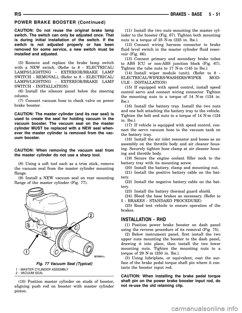
(9) Install a NEW vacuum seal on rear mounting
flange of the master cylinder (Fig. 77).
(10) Position master cylinder on studs of booster,
aligning push rod on booster with master cylinder
piston.(11) Install the two nuts mounting the master cyl-
inder to the booster (Fig. 67). Tighten both mounting
nuts to a torque of 25 N´m (225 in. lbs.).
(12) Connect wiring harness connector to brake
fluid level switch in the master cylinder fluid reser-
voir (Fig. 66).
(13) Connect primary and secondary brake tubes
to ABS ICU or non-ABS junction block (Fig. 67).
Tighten the tube nuts to 17 N´m (145 in lbs.).
(14) Install wiper module (unit). (Refer to 8 -
ELECTRICAL/WIPERS/WASHERS/WIPER MOD-
ULE - INSTALLATION)
(15) If equipped with speed control, install speed
control servo and connect wiring connector. Tighten
the mounting nuts to a torque of 14 N´m (124 in.
lbs.).
(16) Install the battery tray. Install the two nuts
and one bolt attaching the battery tray to the vehicle.
Tighten the bolt and nuts to a torque of 14 N´m (124
in. lbs.).
(17) If vehicle is equipped with speed control, con-
nect the servo vacuum hose to the vacuum tank on
the battery tray.
(18) Install the air inlet resonator and hoses as an
assembly on the throttle body and air cleaner hous-
ing. Securely tighten hose clamp at air cleaner hous-
ing and throttle body.
(19) Secure the engine coolant filler neck to the
battery tray with its mounting screw.
(20) Install the battery, clamp and mounting nut.
(21) Install the positive battery cable on the bat-
tery.
(22) Install the negative battery cable on the bat-
tery.
(23) Install the battery thermal guard shield.
(24) Bleed the base brakes as necessary. (Refer to
5 - BRAKES - STANDARD PROCEDURE)
(25) Road test vehicle to ensure operation of the
brakes.
INSTALLATION - RHD
(1) Position power brake booster on dash panel
using the reverse procedure of its removal (Fig. 75).
(2) Below instrument panel, first install the two
upper nuts mounting the booster to the dash panel,
drawing it into place, then install the two lower
mounting nuts. Tighten the mounting nuts to a
torque of 29 N´m (250 in. lbs.).
(3) Using lubriplate, or equivalent, coat the sur-
face of the brake pedal torque shaft pin where it con-
tacts the booster input rod.
CAUTION: When installing the brake pedal torque
shaft pin on the power brake booster input rod, do
not re-use the old retaining clip.
Fig. 77 Vacuum Seal (Typical)
1 - MASTER CYLINDER ASSEMBLY
2 - VACUUM SEAL
RSBRAKES - BASE5-51
POWER BRAKE BOOSTER (Continued)
Page 292 of 2339
FRONT CONTROL MODULE
DESCRIPTION
The Front Control Module (FCM) is a micro con-
troller based module located in the engine compart-
ment. The FCM mates to the Power Distribution
Center (PDC) to form the Integrated Power Module
(IPM). The IPM connects directly to the battery and
provides the primary means of circuit protection and
power distribution for all vehicle electrical systems.
The FCM controls power to some of these vehicle sys-
tems electrical and electromechanical loads based on
inputs received from hard wired switch inputs and
data received on the Programmable Communications
Interface (PCI) data bus.
For information on the IPM, (Refer to 8 - ELEC-
TRICAL/POWER DISTRIBUTION/INTEGRATED
POWER MODULE - DESCRIPTION)
OPERATION
As messages are sent over the Programmable Com-
munications Interface (PCI) data bus, the Front Con-
trol Module (FCM) reads these messages and controls
power to some of the vehicles electrical systems by
completing the circuit to ground (low side driver) or
completing the circuit to 12 volt power (high side
driver).
The following functions arecontrolledby the
Front Control Module:
²Accessory Relay Actuation
²Brake Transmission Shift Interlock Functions
(BTSI - gas engine only)
²Diesel Cabin Heater (Diesel Engine Vehicles)
²Electronic Back Light (EBL) Rear Defogger
²Front and Rear Blower Motor Relay Actuation
²Front Fog Lamp Relay Actuation
²Washer Motor (front and rear)
²Front Windshield Wiper ªHIº & ªLOº Relay
Actuation
²Front Windshield Wiper ªONº Relay Actuation
²Headlamp Power with Voltage Regulation
²Horn Relay Actuation
²Headlamp Washer Relay Actuation (IF
EQUIPPED - EXPORT ONLY)
²Name Brand Speaker (NBS) Relay Actuation
²Park Lamp Relay Actuation
The following inputs areReceived/Monitoredby
the Front Control Module:
²Ambient Temperature Sensing
²Back-Up switch
²Brake Fluid Level
²B+ Connection Detection
²Engine Crank Signal (Diesel Engine Vehicles)
²Horn Input
²Ignition Switch Start Only
²Ignition Switch Run and Start Only²Stop Lamp Sense
²Washer Fluid Level
²Windshield Wiper Park
DIAGNOSIS AND TESTING
FRONT CONTROL MODULE
The Front Control Module (FCM) is a printed cir-
cuit board based module with a on-board micro-pro-
cessor. The FCM interfaces with other electronic
modules in the vehicle via the Programmable Com-
munications Interface (PCI) data bus. In order to
obtain conclusive testing the PCI data bus and all of
the electronic modules that provide inputs to, or
receive outputs from the FCM must be checked. All
PCI communication faults must be resolved prior to
further diagnosing any front control module related
issues.
The FCM was designed to be diagnosed with an
appropriate diagnostic scan tool, such as the DRB
IIIt. The most reliable, efficient, and accurate means
to diagnose the front control module requires the use
of a DRB IIItscan tool and the proper Body Diag-
nostic Procedures manual.
Before any testing of the FCM is attempted, the
battery should be fully charged and all wire harness
and ground connections inspected around the affected
areas on the vehicle.
REMOVAL
(1) Disconnect and isolate the negative and posi-
tive battery cables from the battery.
(2) Remove the battery (Refer to 8 - ELECTRI-
CAL/BATTERY SYSTEM/BATTERY - REMOVAL).
(3) Using a long flat-bladed screwdriver, gently
twist the Integrated Power Module (IPM) retaining
clip outboard to free the IPM from its mounting
bracket (Fig. 5). Rotate IPM upward to access the
Front Control Module (FCM) retaining screws.
(4) Remove the front control module retaining
screws.
(5) Pull the FCM straight from the IPM assembly
to disconnect the electrical connector (Fig. 6) and
remove the FCM from the vehicle.
INSTALLATION
NOTE: Front Control Module must be programmed
to the correct radio EQ curve using the DRB IIIT.
This will ensure that the audio system is operating
correctly.
(1) Install the Front Control Module (FCM) in the
Integrated Power Module (IPM) assembly by pushing
the 49-way electrical connector straight in.
RSELECTRONIC CONTROL MODULES8E-7