sensor CHRYSLER VOYAGER 2020 Owners Manual
[x] Cancel search | Manufacturer: CHRYSLER, Model Year: 2020, Model line: VOYAGER, Model: CHRYSLER VOYAGER 2020Pages: 516, PDF Size: 28.69 MB
Page 7 of 516
5
SPEED CONTROL — IF EQUIPPED .................... 237 To Activate .................................................. 238To Set A Desired Speed .............................238To Vary The Speed Setting ........................ 238To Accelerate For Passing .........................239
To Resume Speed ..................................... 239To Deactivate ............................................239
ADAPTIVE CRUISE CONTROL (ACC) —
IF EQUIPPED ....................................................... 239
Adaptive Cruise Control (ACC)
Operation ....................................................241 Activating Adaptive Cruise
Control (ACC) ..............................................241 To Activate/Deactivate .............................. 242
To Set A Desired ACC Speed .....................242To Cancel ....................................................243
To Turn Off .................................................. 243To Resume .................................................243
To Vary The Speed Setting ........................ 243Setting The Following Distance In ACC.....245
Overtake Aid ...............................................246ACC Operation At Stop ...............................246
Adaptive Cruise Control (ACC) Menu ........247Display Warnings And Maintenance.........247
Precautions While Driving With ACC .........249
General Information ..................................251Normal (Fixed Speed) Cruise Control
Mode...........................................................252 PARKSENSE REAR PARK ASSIST —
IF EQUIPPED ...................................................... 254
ParkSense Sensors ................................... 255
ParkSense Visual Alert .............................. 255
ParkSense Display ..................................... 255
Enabling And Disabling ParkSense .......... 257Service The ParkSense Rear Park Assist
System ........................................................ 258 Cleaning The ParkSense System.............. 258
ParkSense System Usage Precautions .... 258
PARKSENSE FRONT AND REAR PARK
ASSIST — IF EQUIPPED .....................................259
ParkSense Sensors ................................... 261
ParkSense Visual Alert .............................. 261
ParkSense Display ..................................... 261
Enabling And Disabling ParkSense .......... 266Service The ParkSense Park Assist
System ........................................................ 266 Cleaning The ParkSense System.............. 267
ParkSense System Usage Precautions .... 267
PARKSENSE ACTIVE PARK ASSIST
SYSTEM — IF EQUIPPED ....................................268
Enabling And Disabling The ParkSense
Active Park Assist System ......................... 268 Parallel Parking Space Assistance
Operation/Display...................................... 269 Perpendicular Parking Space Assistance
Operation/Display...................................... 274 LANESENSE — IF EQUIPPED ........................... 280
LaneSense Operation................................ 280
Turning LaneSense On Or Off ................... 280
LaneSense Warning Message .................. 281Left Lane Departure — Only Left Lane
Detected..................................................... 281 Changing LaneSense Status..................... 282
PARKVIEW REAR BACK UP CAMERA ............. 283
SURROUND VIEW CAMERA SYSTEM — IF
EQUIPPED .......................................................... 284
REFUELING THE VEHICLE ................................. 286
VEHICLE LOADING ............................................. 288 Certification Label ..................................... 288
TRAILER TOWING ............................................. 289
Common Towing Definitions ..................... 289
Trailer Hitch Classification ........................ 291
Trailer Towing Weights (Maximum Trailer
Weight Ratings) ......................................... 291 Vehicle Loading Chart ............................... 292Trailer And Tongue Weight ....................... 294Towing Requirements .............................. 294
Towing Tips ............................................... 297
RECREATIONAL TOWING (BEHIND
MOTORHOME, ETC.) ......................................... 298
Towing This Vehicle Behind Another
Vehicle ........................................................ 298 Recreational Towing — All Models ............ 298
DRIVING TIPS ..................................................... 299
Driving On Slippery Surfaces .................... 299Driving Through Water ............................. 299
20_RU_OM_EN_US_t.book Page 5
Page 34 of 516
32GETTING TO KNOW YOUR VEHICLE
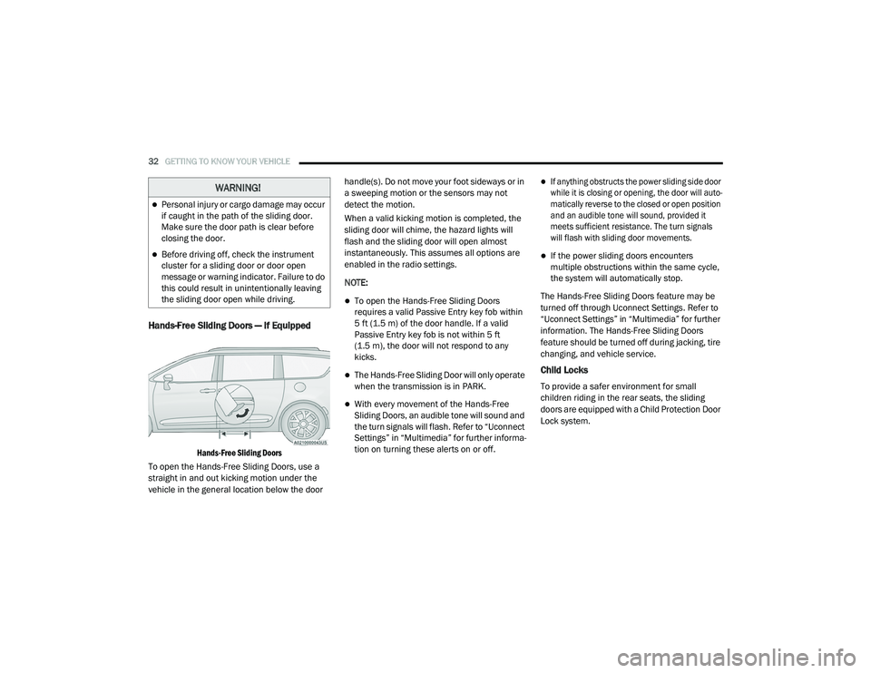
Hands-Free Sliding Doors — If Equipped
Hands-Free Sliding Doors
To open the Hands-Free Sliding Doors, use a
straight in and out kicking motion under the
vehicle in the general location below the door handle(s). Do not move your foot sideways or in
a sweeping motion or the sensors may not
detect the motion.
When a valid kicking motion is completed, the
sliding door will chime, the hazard lights will
flash and the sliding door will open almost
instantaneously. This assumes all options are
enabled in the radio settings.
NOTE:
To open the Hands-Free Sliding Doors
requires a valid Passive Entry key fob within
5 ft (1.5 m) of the door handle. If a valid
Passive Entry key fob is not within 5 ft
(1.5 m), the door will not respond to any
kicks.
The Hands-Free Sliding Door will only operate
when the transmission is in PARK.
With every movement of the Hands-Free
Sliding Doors, an audible tone will sound and
the turn signals will flash. Refer to “Uconnect
Settings” in “Multimedia” for further informa
-
tion on turning these alerts on or off.
If anything obstructs the power sliding side door
while it is closing or opening, the door will auto -
matically reverse to the closed or open position
and an audible tone will sound, provided it
meets sufficient resistance. The turn signals
will flash with sliding door movements.
If the power sliding doors encounters
multiple obstructions within the same cycle,
the system will automatically stop.
The Hands-Free Sliding Doors feature may be
turned off through Uconnect Settings. Refer to
“Uconnect Settings” in “Multimedia” for further
information. The Hands-Free Sliding Doors
feature should be turned off during jacking, tire
changing, and vehicle service.
Child Locks
To provide a safer environment for small
children riding in the rear seats, the sliding
doors are equipped with a Child Protection Door
Lock system.
WARNING!
Personal injury or cargo damage may occur
if caught in the path of the sliding door.
Make sure the door path is clear before
closing the door.
Before driving off, check the instrument
cluster for a sliding door or door open
message or warning indicator. Failure to do
this could result in unintentionally leaving
the sliding door open while driving.
20_RU_OM_EN_US_t.book Page 32
Page 62 of 516
60GETTING TO KNOW YOUR VEHICLE
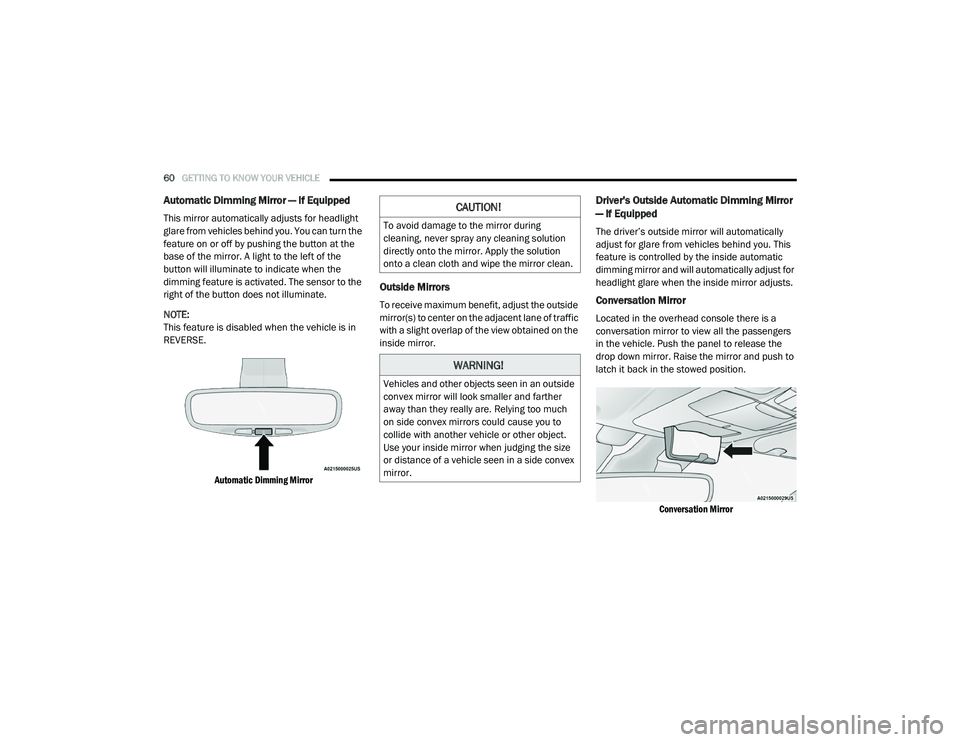
Automatic Dimming Mirror — If Equipped
This mirror automatically adjusts for headlight
glare from vehicles behind you. You can turn the
feature on or off by pushing the button at the
base of the mirror. A light to the left of the
button will illuminate to indicate when the
dimming feature is activated. The sensor to the
right of the button does not illuminate.
NOTE:
This feature is disabled when the vehicle is in
REVERSE.
Automatic Dimming Mirror
Outside Mirrors
To receive maximum benefit, adjust the outside
mirror(s) to center on the adjacent lane of traffic
with a slight overlap of the view obtained on the
inside mirror.
Driver's Outside Automatic Dimming Mirror
— If Equipped
The driver’s outside mirror will automatically
adjust for glare from vehicles behind you. This
feature is controlled by the inside automatic
dimming mirror and will automatically adjust for
headlight glare when the inside mirror adjusts.
Conversation Mirror
Located in the overhead console there is a
conversation mirror to view all the passengers
in the vehicle. Push the panel to release the
drop down mirror. Raise the mirror and push to
latch it back in the stowed position.
Conversation Mirror
CAUTION!
To avoid damage to the mirror during
cleaning, never spray any cleaning solution
directly onto the mirror. Apply the solution
onto a clean cloth and wipe the mirror clean.
WARNING!
Vehicles and other objects seen in an outside
convex mirror will look smaller and farther
away than they really are. Relying too much
on side convex mirrors could cause you to
collide with another vehicle or other object.
Use your inside mirror when judging the size
or distance of a vehicle seen in a side convex
mirror.
20_RU_OM_EN_US_t.book Page 60
Page 71 of 516
GETTING TO KNOW YOUR VEHICLE69
Windshield Washers
To use the washer, pull the lever rearward
toward you and hold while spray is desired. If
the lever is pulled while on the intermittent
setting, the wipers will turn on and operate for
several wipe cycles after the lever is released,
and then resume the intermittent interval
previously selected. If the lever is pulled while
the wipers are in the off position, the wipers will
operate several wipe cycles, then turn off.
Mist Feature
Use the Mist feature when weather conditions
make occasional usage of the wipers
necessary. Push the lever upward to the MIST
position and release for a single wiping cycle.
NOTE:
The mist feature does not activate the washer
pump; therefore, no washer fluid will be sprayed
on the windshield. The wash function must be
used in order to spray the windshield with
washer fluid.
Rain Sensing Wipers — If Equipped
This feature senses rain or snowfall on the
windshield and automatically activates the
wipers for the driver. This feature is especially
useful for road splash or overspray from the
windshield washers of the vehicle ahead.
Rotate the end of the windshield wiper lever to
one of the four intermittent wiper sensitivity
settings to activate this feature.
The sensitivity of the system is adjustable from
the windshield wiper lever. Wiper sensitivity
position 3 has been calibrated for best overall
wiping sensitivity. If the operator desires more
wiping sensitivity, they may select sensitivity
position 4. If the operator desires less wiping
sensitivity, they may select sensitivity positions
2 or 1. Place the windshield wiper lever in the
OFF position when not using the system.
NOTE:
The Rain Sensing feature will not operate when
the wiper switch is in the low or high position.
The Rain Sensing feature may not function
properly when ice or dried saltwater is
present on the windshield.
Use of Rain-X or products containing wax or
silicone may reduce rain sensor performance.
The Rain Sensing feature can be turned on
and off through the Uconnect System. Refer
to “Uconnect Settings” in “Multimedia” for
further information.
The Rain Sensing system has protective
features for the wiper blades and arms. It will
not operate under the following conditions:
Low Temperature Wipe Inhibit — The Rain
Sensing feature will not operate when the
ignition is first placed in the ON position,
when the vehicle is stationary and the
outside temperature is below 32°F (0°C),
unless the wiper control on the windshield
wiper lever is moved, the vehicle speed
becomes greater than 3 mph (5 km/h) or the
outside temperature rises above freezing.
2
20_RU_OM_EN_US_t.book Page 69
Page 103 of 516
GETTING TO KNOW YOUR VEHICLE101
To Close The Liftgate
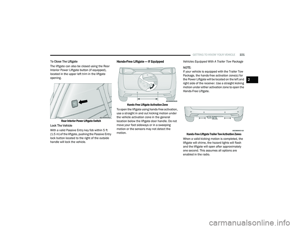
The liftgate can also be closed using the Rear
Interior Power Liftgate button (if equipped),
located in the upper left trim in the liftgate
opening.
Rear Interior Power Liftgate Switch
Lock The Vehicle
With a valid Passive Entry key fob within 5 ft
(1.5 m) of the liftgate, pushing the Passive Entry
lock button located to the right of the outside
handle will lock the vehicle.Hands-Free Liftgate — If Equipped
Hands-Free Liftgate Activation Zone
To open the liftgate using hands-free activation,
use a straight in and out kicking motion under
the vehicle activation zone in the general
location below the liftgate door handle. Do not
move your foot sideways or in a sweeping
motion or the sensors may not detect the
motion. Vehicles Equipped With A Trailer Tow Package
NOTE:
If your vehicle is equipped with the Trailer Tow
Package, the hands-free activation zone(s) for
the Power Liftgate will be located on the left and
right side of the receiver. Use a straight kicking
motion under either activation zone to open the
Hands-Free Liftgate.
Hands-Free Liftgate Trailer Tow Activation Zones
When a valid kicking motion is completed, the
liftgate will chime, the hazard lights will flash
and the liftgate will open after approximately
one second. This assumes all options are
enabled in the radio.
2
20_RU_OM_EN_US_t.book Page 101
Page 104 of 516
102GETTING TO KNOW YOUR VEHICLE
(Continued)
NOTE:
To open the Hands-Free Liftgate requires a valid
Passive Entry key fob within 5 ft (1.5 m) of the
door handle. If a valid Passive Entry key fob is
not within 5 ft (1.5 m), the liftgate will not
respond to any kicks.
NOTE:
The Hands-Free Liftgate will only operate
when the transmission is in PARK.
If anything obstructs the Hands-Free Liftgate
while it is opening or closing, the liftgate will
automatically reverse to the closed position,
provided it meets sufficient resistance.
There are pinch sensors attached to the side
of the liftgate opening. Light pressure
anywhere along these strips will cause the
liftgate to return to the open position.
If the power liftgate encounters multiple
obstructions within the same cycle, the
system will automatically stop. If this occurs,
the liftgate must be operated manually.
The power liftgate will release, but not power
open, in temperatures below −12°F
(−24°C). Be sure to remove any buildup of
snow or ice from the liftgate before opening
the liftgate.
If the liftgate is left open for an extended
period of time, the liftgate may need to be
closed manually to reset power liftgate func-
tionality. Gas props support the liftgate in the open
position. However, because the gas pressure
drops with temperature, it may be necessary to
assist the props when opening the liftgate in
cold weather.
NOTE:
Allow the power system to open the liftgate.
Manually pushing or pulling the liftgate may
activate the liftgate obstacle detection feature
and stop the power operation or reverse its
direction.
CAUTION!
The Hands-Free Liftgate feature may be
turned on or off in Uconnect Settings. Refer to
“Uconnect Settings” in “Multimedia” for
further information. The Hands-Free Liftgate
feature should be turned off during Jacking,
Tire Changing, and Vehicle Service.
WARNING!
Driving with the liftgate open can allow
poisonous exhaust gases into your vehicle.
You and your passengers could be injured
by these fumes. Keep the liftgate closed
when you are operating the vehicle.
If you are required to drive with the liftgate
open, make sure that all windows are
closed, and the climate control blower
switch is set at high speed. Do not use the
recirculation mode.
WARNING!
During power operation, personal injury or
cargo damage may occur. Ensure the liftgate
travel path is clear. Make sure the liftgate is
closed and latched before driving away.
WARNING!
(Continued)
20_RU_OM_EN_US_t.book Page 102
Page 140 of 516
138GETTING TO KNOW YOUR INSTRUMENT PANEL
Speed Warning — If Equipped
Push and release the up or down arrow button
until Speed Warning is highlighted in the
instrument cluster display. Push and release the
OK button to enter speed warning. Use the up or
down arrow button to turn the speed warning ON
or OFF, then push and release the OK button to
confirm the selection. If the ON status is selected,
use the up or down arrow button to set the
desired speed, then push the OK button to set
the speed for the speed warning. A speed
warning telltale will illuminate in the instrument
cluster, with a number matching the set speed,
with a pop up message to inform the driver that
the speed warning has been set to the desired
speed. Each time the set speed is exceeded, a
single chime will sound and a pop up warning
message will display. If the set speed is exceeded
more than 2 mph (3 km/h), a continuous chime
will sound for up to 10 seconds, or until the speed
is no longer exceeded. The telltale in the
instrument cluster will also change from white to
yellow, and a pop up warning message will pop up
on the instrument cluster display.
NOTE:
Speed Warning is unavailable while KeySense
is in use.
Battery Saver On/Battery Saver Mode
Message — Electrical Load Reduction
Actions — If Equipped
This vehicle is equipped with an Intelligent
Battery Sensor (IBS) to perform additional
monitoring of the electrical system and status
of the vehicle battery.
In cases when the IBS detects charging system
failure, or the 12 Volt vehicle battery conditions
are deteriorating, electrical load reduction
actions will take place to extend the driving time
and distance of the vehicle. This is done by
reducing power to or turning off non-essential
12 Volt electrical loads. Load reduction will be
functional when the vehicle propulsion system
is active.
The vehicle may not be running depending on
the HV battery SOC or temperature. It will
display a message if there is a risk of battery
depletion to the point where the vehicle may
stall due to lack of electrical supply, or will not
restart after the current drive cycle.
When 12 Volt load reduction is activated, the
message “Battery Saver On” or “Battery Saver
Mode” will appear in the instrument cluster
display. These messages indicate the vehicle battery
has a low state of charge and continues to lose
electrical charge at a rate that the charging
system cannot sustain.
NOTE:
The charging system is independent from
load reduction. The charging system
performs a diagnostic on the charging
system continuously.
If the Battery Charge Warning Light is on it
may indicate a problem with the charging
system. Refer to “Battery Charge Warning
Light” in this chapter for further information.
The electrical loads that may be switched off (if
equipped), and vehicle functions which can be
effected by load reduction:
Heated Seat/Vented Seats/Heated Wheel
Heated/Cooled Cup Holders — If Equipped
Rear Defroster And Heated Mirrors
HVAC System
115 Volts AC Power Inverter System
Audio and Telematics System
20_RU_OM_EN_US_t.book Page 138
Page 149 of 516
GETTING TO KNOW YOUR INSTRUMENT PANEL147
indicated on the vehicle placard or tire inflation
pressure label, you should determine the
proper tire inflation pressure for those tires.
As an added safety feature, your vehicle has
been equipped with a Tire Pressure Monitoring
System (TPMS) that illuminates a low tire
pressure telltale when one or more of your tires is
significantly under-inflated. Accordingly, when
the low tire pressure telltale illuminates, you
should stop and check your tires as soon as
possible, and inflate them to the proper pressure.
Driving on a significantly under-inflated tire
causes the tire to overheat and can lead to tire
failure. Under-inflation also reduces fuel
efficiency and tire tread life, and may affect the
vehicle’s handling and stopping ability.
Please note that the TPMS is not a substitute for
proper tire maintenance, and it is the driver’s
responsibility to maintain correct tire pressure,
even if under-inflation has not reached the level
to trigger illumination of the TPMS low tire
pressure telltale.
Your vehicle has also been equipped with a TPMS
malfunction indicator to indicate when the
system is not operating properly. The TPMS
malfunction indicator is combined with the low
tire pressure telltale. When the system detects a
malfunction, the telltale will flash for
approximately one minute and then remain
continuously illuminated. This sequence will
continue upon subsequent vehicle start-ups as
long as the malfunction exists. When the
malfunction indicator is illuminated, the system
may not be able to detect or signal low tire
pressure as intended. TPMS malfunctions may
occur for a variety of reasons, including the
installation of replacement or alternate tires or
wheels on the vehicle that prevent the TPMS from
functioning properly. Always check the TPMS
malfunction telltale after replacing one or more
tires or wheels on your vehicle to ensure that the
replacement or alternate tires and wheels allow
the TPMS to continue to function properly.
Yellow Indicator Lights
Forward Collision Warning Off Indicator Light
— If Equipped
This indicator light illuminates to
indicate that Forward Collision
Warning is off.
CAUTION!
The TPMS has been optimized for the original
equipment tires and wheels. TPMS pressures
and warning have been established for the tire
size equipped on your vehicle. Undesirable
system operation or sensor damage may result
when using replacement equipment that is not
of the same size, type, and/or style.
Aftermarket wheels can cause sensor damage.
Using aftermarket tire sealants may cause the
Tire Pressure Monitoring System (TPMS)
sensor to become inoperable. After using an
aftermarket tire sealant it is recommended
that you take your vehicle to an authorized
dealer to have your sensor function checked.
3
20_RU_OM_EN_US_t.book Page 147
Page 157 of 516
SAFETY155
(Continued)
ESC uses sensors in the vehicle to determine the
vehicle path intended by the driver and compares
it to the actual path of the vehicle. When the actual
path does not match the intended path, ESC
applies the brake of the appropriate wheel to
assist in counteracting the oversteer or understeer
condition.
Oversteer — when the vehicle is turning more
than appropriate for the steering wheel position.
Understeer — when the vehicle is turning less
than appropriate for the steering wheel position.
The “ESC Activation/Malfunction Indicator Light”
located in the instrument cluster will start to flash
as soon as the ESC system becomes active. The
“ESC Activation/Malfunction Indicator Light” also
flashes when the TCS is active. If the “ESC
Activation/Malfunction Indicator Light” begins to
flash during acceleration, ease up on the
accelerator and apply as little throttle as possible.
Be sure to adapt your speed and driving to the
prevailing road conditions.
WARNING!
Electronic Stability Control (ESC) cannot
prevent the natural laws of physics from
acting on the vehicle, nor can it increase the
traction afforded by prevailing road condi -
tions. ESC cannot prevent accidents,
including those resulting from excessive
speed in turns, driving on very slippery
surfaces, or hydroplaning. ESC also cannot
prevent accidents resulting from loss of
vehicle control due to inappropriate driver
input for the conditions. Only a safe, atten -
tive, and skillful driver can prevent acci -
dents. The capabilities of an ESC equipped
vehicle must never be exploited in a reckless
or dangerous manner which could jeopar -
dize the user’s safety or the safety of others.
Vehicle modifications, or failure to properly
maintain your vehicle, may change the
handling characteristics of your vehicle,
and may negatively affect the performance
of the ESC system. Changes to the steering
system, suspension, braking system, tire
type and size or wheel size may adversely
affect ESC performance. Improperly
inflated and unevenly worn tires may also
degrade ESC performance. Any vehicle
modification or poor vehicle maintenance
that reduces the effectiveness of the ESC
system can increase the risk of loss of
vehicle control, vehicle rollover, personal
injury and death.
WARNING! (Continued)
4
20_RU_OM_EN_US_t.book Page 155
Page 160 of 516
158SAFETY
Towing With HSA
HSA will also provide assistance to mitigate roll
back while towing a trailer.
Disabling And Enabling HSA
This feature can be turned on or turned off. To
change the current setting, proceed as follows:
If disabling HSA using Uconnect Settings,
refer to “Uconnect Settings” in “Multimedia”
for further information.
Rain Brake Support (RBS)
Rain Brake Support (RBS) may improve braking
performance in wet conditions. It will
periodically apply a small amount of brake
pressure to remove any water buildup on the
front brake rotors. It functions when the
windshield wipers are in LO or HI speed. When
RBS is active, there is no notification to the
driver and no driver interaction is required.
Ready Alert Braking (RAB)
Ready Alert Braking (RAB) may reduce the time
required to reach full braking during emergency
braking situations. It anticipates when an
emergency braking situation may occur by
monitoring how fast the throttle is released by
the driver. The Electronic Brake Control (EBC)
system will prepare the brake system for a
panic stop.
Traction Control System (TCS)
The Traction Control System (TCS) monitors the
amount of wheel spin of each of the driven
wheels. If wheel spin is detected, the TCS may
apply brake pressure to the spinning wheel(s)
and/or reduce vehicle power to provide
enhanced acceleration and stability. A feature
of the TCS, Brake Limited Differential (BLD),
functions similar to a limited slip differential
and controls the wheel spin across a driven
axle. If one wheel on a driven axle is spinning
faster than the other, the system will apply the
brake of the spinning wheel. This will allow more
vehicle torque to be applied to the wheel that is
not spinning. BLD may remain enabled even if
TCS and the Electronic Stability Control (ESC)
are in a reduced mode.
Trailer Sway Control (TSC)
Trailer Sway Control (TSC) uses sensors in the
vehicle to recognize an excessively swaying
trailer and will take the appropriate actions to
attempt to stop the sway. TSC will become
active automatically once an excessively
swaying trailer is recognized. Note that TSC
cannot stop all trailers from swaying. Always
use caution when towing a trailer and follow the
trailer tongue weight recommendations. Refer
WARNING!
If you use a trailer brake controller with your
trailer, the trailer brakes may be activated
and deactivated with the brake switch. If so,
there may not be enough brake pressure to
hold both the vehicle and the trailer on a hill
when the brake pedal is released. In order to
avoid rolling down an incline while resuming
acceleration, manually activate the trailer
brake or apply more vehicle brake pressure
prior to releasing the brake pedal.
HSA is not a parking brake. Always apply
the parking brake fully when exiting your
vehicle. Also, be certain to place the trans -
mission in PARK.
Failure to follow these warnings can result
in a collision or serious personal injury.
20_RU_OM_EN_US_t.book Page 158