ESP CHRYSLER VOYAGER 2021 Owners Manual
[x] Cancel search | Manufacturer: CHRYSLER, Model Year: 2021, Model line: VOYAGER, Model: CHRYSLER VOYAGER 2021Pages: 348, PDF Size: 18.73 MB
Page 2 of 348

The driver’s primary responsibility is the safe operation of the vehicle. Driving while distracted can result in loss of vehicle control, resulting in an accident and personal injury.
FCA US LLC strongly recommends that the driver use extreme caution when using any device or feature that may take their attention off the road. Use of any electrical devices,
such as cellular telephones
, computers, portable radios, vehicle navigation or other devices, by the driver while the vehicle is moving is dangerous and could lead to a serious
accident. Texting while driving is also dangerous and should never be done while the vehicle is moving. If you find yourself unable to devote your full attention to vehicle
operation, pull off the road to a safe location and stop your vehicle. Some states or provinces prohibit the use of cellular telephones or texting while driving. It is always the driver’s
responsibility to comply with all local laws.
This Owner’s Manual has been prepared to help you get acquainted with your new Chrysler
brand vehicle and to provide a convenient reference source for common questions.
Not all features shown in this manual may apply to your vehicle. For additional information, visit mopar.com/om (U.S.), owners.mopar.ca (Canada) or your local Chrysler
brand dealer.
Drunk driving is one of the most frequent causes of accidents. Your driving ability can be seriously impaired with blood alcohol
levels far below the legal minimum. If you are drinking, don’t drive. Ride with a designated non-drinking driver, call a cab, a friend
or use public transportation. DRIVING AND ALCOHOL
Driving after drinking can lead to an accident. Your perceptions are less sharp, your reflexes are slower and your
judgment is impaired when you have been drinking. Never drink and then drive.
WARNING!
WARNING:
Operating, servicing and maintaining a passenger vehicle or off-highway motor vehicle can
expose you to chemicals including engine exhaust, carbon monoxide, phthalates, and lead, which are known to
the State of California to cause cancer and birth defects or other reproductive harm. To minimize exposure,
avoid breathing exhaust, do not idle the engine except as necessary, service your vehicle in a well-ventilated area
and wear gloves or wash your hands frequently when servicing your vehicle. For more information go to
www.P65Warnings.ca.gov/passenger-vehicle.
This Owner’s Manual illustrates and describes the operation of features and equipment that are either standard or optional on this vehicle. This manual may also include a
description of features and equipment that are no longer available or were not ordered on this vehicle. Please disregard any features and equipment described in this manual that
are not on this vehicle. FCA US LLC reserves the right to make changes in design and specifications, and/or make additions to or improvements to its products without imposing
any obligation upon itself to install them on products previously manufactured.
With respect to any vehicles sold in Canada, the name FCA US LLC shall be deemed to be deleted and the name FCA Canada Inc. used in substitution therefore.
This Owner’s Manual is intended to familiarize you with the important features of your vehicle. Your most up-to-date Owner’s Manual, Navigation/ Uconnect manuals and Warranty
Booklet can be found by visiting the website on the back cover.
U.S. Residents: If you are the first registered retail owner of your vehicle, you may obtain a complimentary printed copy of the Warranty Booklet by calling 1-800-247-9753 or by
contacting your dealer. Replacement kits can be purchased by visiting www.techauthority.com.
Canadian Residents: If you are the first registered retail owner of your vehicle, you may obtain a complimentary printed copy of the Warranty Booklet or purchase a replacement
kit by calling 1-800-387-1143 or by contacting your dealer.
Page 7 of 348
5
UCONNECT MODES ............................................. 159 Steering Wheel Audio Controls ................... 159
Radio Mode .................................................. 160
Media Mode .................................................. 168
Phone Mode ................................................. 170
ANDROID AUTO™ & APPLE CARPLAY® —
IF EQUIPPED ........................................................ 181
Android Auto™ .............................................. 181Apple CarPlay®.............................................. 183Android Auto™ And Apple CarPlay®
Tips And Tricks............................................... 185
RADIO OPERATION AND MOBILE PHONES ..... 185
Regulatory And Safety Information .............. 185
SAFETY
SAFETY FEATURES .............................................. 186Anti-Lock Brake System (ABS) ..................... 186
Electronic Brake Control (EBC) System ...... 187
AUXILIARY DRIVING SYSTEMS .......................... 192
Blind Spot Monitoring (BSM) —
If Equipped..................................................... 192
Forward Collision Warning (FCW)
With Mitigation — If Equipped....................... 196
Tire Pressure Monitoring System
(TPMS) ........................................................... 199 OCCUPANT RESTRAINT SYSTEMS ................... 202
Occupant Restraint Systems Features ....... 202
Important Safety Precautions ...................... 202Seat Belt Systems ........................................ 203Supplemental Restraint Systems (SRS) ...... 212Child Restraints ............................................ 225
SAFETY TIPS ...................................................... 241
Transporting Passengers .............................. 241Transporting Pets ........................................ 242Safety Checks You Should Make
Inside The Vehicle ........................................ 242Periodic Safety Checks You Should
Make Outside The Vehicle ............................ 243
Exhaust Gas ................................................. 244
Carbon Monoxide Warnings ........................ 244IN CASE OF EMERGENCY
HAZARD WARNING FLASHERS......................... 245
ASSIST AND SOS MIRROR —
IF EQUIPPED ....................................................... 245
JACKING AND TIRE CHANGING —
IF EQUIPPED ...................................................... 249
Preparations For Jacking ............................. 249
Jack And Spare Tire Location ....................... 250
Equipment Removal ..................................... 250
Jacking Instructions ..................................... 251
Road Tire Installation .................................... 254
Portable Air Compressor —
If Equipped..................................................... 255Return Inflatable Spare Tire ........................ 256 TIRE SERVICE KIT — IF EQUIPPED ..................... 257
JUMP STARTING .................................................. 262
Preparations For Jump Start ........................ 262Jump Starting Procedure .............................. 263
REFUELING IN EMERGENCY –
IF EQUIPPED ........................................................ 264
IF YOUR ENGINE OVERHEATS ............................ 265
MANUAL PARK RELEASE .................................. 266
FREEING A STUCK VEHICLE .............................. 267
TOWING A DISABLED VEHICLE ......................... 268
ENHANCED ACCIDENT RESPONSE
SYSTEM (EARS) ................................................... 270
EVENT DATA RECORDER (EDR) ......................... 270
SERVICING AND MAINTENANCE
SCHEDULED SERVICING .................................... 271 Maintenance Plan ......................................... 272
ENGINE COMPARTMENT ................................... 275
3.6L Engine ................................................... 275
Checking Oil Level ......................................... 276
Adding Washer Fluid .................................... 276
Maintenance-Free Battery ........................... 276
Pressure Washing ......................................... 277
21_RUV_OM_EN_USC_t.book Page 5
Page 16 of 348
14GETTING TO KNOW YOUR VEHICLE
Programming And Requesting Additional
Key Fobs
Programming the key fob may be performed by an
authorized dealer.
NOTE:
Once a key fob is programmed to a vehicle, it
cannot be repurposed and reprogrammed to
another vehicle.
Only key fobs that are programmed to the
vehicle electronics can be used to start and
operate the vehicle. Duplication of key fobs may be performed at an
authorized dealer. This procedure consists of
programming a blank key fob to the vehicle
electronics.
NOTE:When having the Sentry Key Immobilizer System
serviced, bring all vehicle keys with you to an
authorized dealer.
KeySense Features — If Equipped
This feature provides the vehicle owner with the
ability to customize vehicle settings that can be
applied to determine the driving experience for
other drivers of the vehicle. The vehicle settings
are protected by a unique 4-digit PIN, which the
vehicle owner creates when accessing the specific
settings for the first time. KeySense also has additional features that are
always enabled when the specific key is in use that
cannot be set by the vehicle owner. While this
specific key fob is in use, the vehicle will respond
accordingly to the customized vehicle settings and
mandatory features. This includes enhanced
driving assistance features, increased driver
alerts, and the locking of certain optional features.
Settings can be customized within the Uconnect
system
Úpage 142.
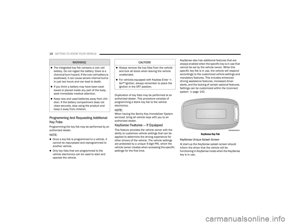
KeySense Key Fob
KeySense Unique Splash Screen
At start-up the KeySense splash screen should
inform the driver that the vehicle will be
functioning in KeySense mode when the KeySense
key is in use.
WARNING!
The integrated key fob contains a coin cell
battery. Do not ingest the battery; there is a
chemical burn hazard. If the coin cell battery is
swallowed, it can cause severe internal burns
in just two hours and can lead to death.
If you think a battery may have been swal-
lowed or placed inside any part of the body,
seek immediate medical attention.
Keep new and used batteries away from chil -
dren. If the battery compartment does not
close securely, stop using the product and
keep it away from children.
CAUTION!
Always remove the key fobs from the vehicle
and lock all doors when leaving the vehicle
unattended.
For vehicles equipped with Keyless Enter ‘n
Go™ Ignition, always remember to place the
ignition in the OFF position.
21_RUV_OM_EN_USC_t.book Page 14
Page 24 of 348
22GETTING TO KNOW YOUR VEHICLE
KEYLESS ENTER ‘N GO™ — PASSIVE
E
NTRY
The Passive Entry system is an enhancement to
the vehicle’s Remote Keyless Entry system and a
feature of Keyless Enter ‘n Go™ — Passive Entry.
This feature allows you to lock and unlock the
vehicle’s door(s) without having to push the key fob
lock or unlock buttons.
NOTE:
Passive Entry may be programmed on/off
through the Uconnect system Úpage 142.
The key fob may not be detected by the vehicle
passive entry system if it is located next to a
mobile phone, laptop, or other electronic device;
these devices may block the key fob’s wireless
signal and prevent the passive entry handle
from locking/unlocking the vehicle.
If set by the customer in the Uconnect Settings,
unlocking with Passive Entry will initiate illumi -
nated approach (low beams, license plate lamp,
position lamps) for the time 0, 30 (default),
60 or 90 seconds. Passive Entry also initiates
two flashes of the turn lamps.
If wearing gloves, or if it has been
raining/snowing on the Passive Entry door
handle, the unlock sensitivity can be affected,
resulting in a slower response time.
If the vehicle is unlocked by Passive Entry and
no door is opened within 60 seconds, the
vehicle will re-lock and will arm the security
system (if equipped).
The sliding side doors can be unlocked from the
outside using the Passive Entry system.
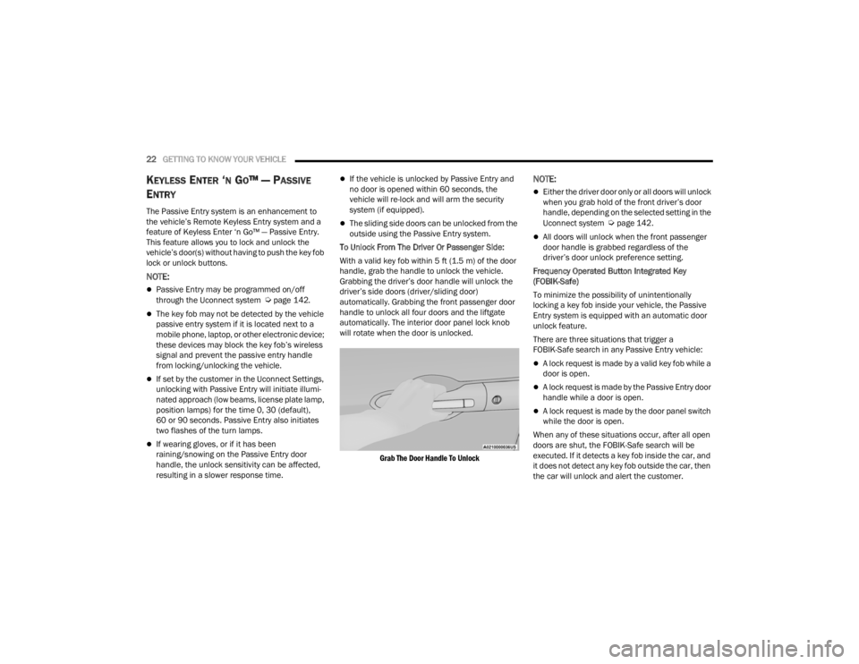
To Unlock From The Driver Or Passenger Side:
With a valid key fob within 5 ft (1.5 m) of the door
handle, grab the handle to unlock the vehicle.
Grabbing the driver’s door handle will unlock the
driver’s side doors (driver/sliding door)
automatically. Grabbing the front passenger door
handle to unlock all four doors and the liftgate
automatically. The interior door panel lock knob
will rotate when the door is unlocked.
Grab The Door Handle To Unlock
NOTE:
Either the driver door only or all doors will unlock
when you grab hold of the front driver’s door
handle, depending on the selected setting in the
Uconnect system
Úpage 142.
All doors will unlock when the front passenger
door handle is grabbed regardless of the
driver’s door unlock preference setting.
Frequency Operated Button Integrated Key
(FOBIK-Safe)
To minimize the possibility of unintentionally
locking a key fob inside your vehicle, the Passive
Entry system is equipped with an automatic door
unlock feature.
There are three situations that trigger a
FOBIK-Safe search in any Passive Entry vehicle:
A lock request is made by a valid key fob while a
door is open.
A lock request is made by the Passive Entry door
handle while a door is open.
A lock request is made by the door panel switch
while the door is open.
When any of these situations occur, after all open
doors are shut, the FOBIK-Safe search will be
executed. If it detects a key fob inside the car, and
it does not detect any key fob outside the car, then
the car will unlock and alert the customer.
21_RUV_OM_EN_USC_t.book Page 22
Page 29 of 348
GETTING TO KNOW YOUR VEHICLE27
STEERING WHEEL
TILT/TELESCOPING STEERING COLUMN
This feature allows you to tilt the steering column
upward or downward. It also allows you to lengthen
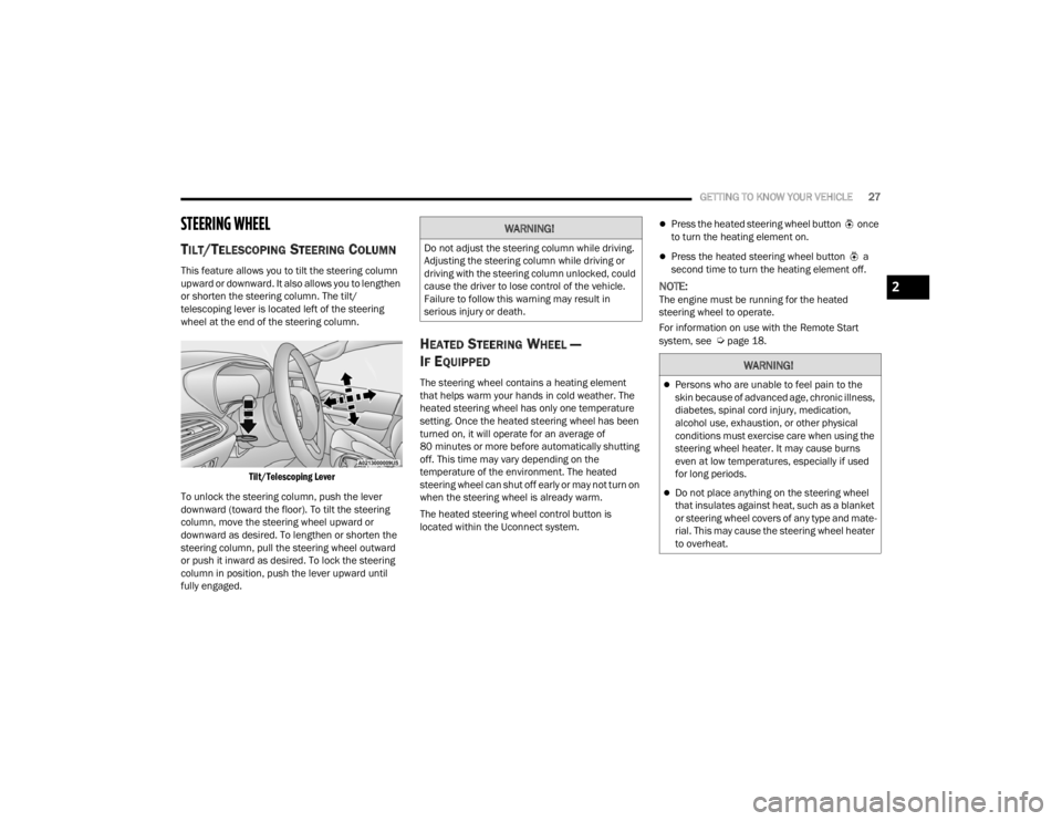
or shorten the steering column. The tilt/
telescoping lever is located left of the steering
wheel at the end of the steering column.
Tilt/Telescoping Lever
To unlock the steering column, push the lever
downward (toward the floor). To tilt the steering
column, move the steering wheel upward or
downward as desired. To lengthen or shorten the
steering column, pull the steering wheel outward
or push it inward as desired. To lock the steering
column in position, push the lever upward until
fully engaged.
HEATED STEERING WHEEL —
I
F EQUIPPED
The steering wheel contains a heating element
that helps warm your hands in cold weather. The
heated steering wheel has only one temperature
setting. Once the heated steering wheel has been
turned on, it will operate for an average of
80 minutes or more before automatically shutting
off. This time may vary depending on the
temperature of the environment. The heated
steering wheel can shut off early or may not turn on
when the steering wheel is already warm.
The heated steering wheel control button is
located within the Uconnect system.
Press the heated steering wheel button once
to turn the heating element on.
Press the heated steering wheel button a
second time to turn the heating element off.
NOTE:The engine must be running for the heated
steering wheel to operate.
For information on use with the Remote Start
system, see
Úpage 18.
WARNING!
Do not adjust the steering column while driving.
Adjusting the steering column while driving or
driving with the steering column unlocked, could
cause the driver to lose control of the vehicle.
Failure to follow this warning may result in
serious injury or death.
WARNING!
Persons who are unable to feel pain to the
skin because of advanced age, chronic illness,
diabetes, spinal cord injury, medication,
alcohol use, exhaustion, or other physical
conditions must exercise care when using the
steering wheel heater. It may cause burns
even at low temperatures, especially if used
for long periods.
Do not place anything on the steering wheel
that insulates against heat, such as a blanket
or steering wheel covers of any type and mate -
rial. This may cause the steering wheel heater
to overheat.
2
21_RUV_OM_EN_USC_t.book Page 27
Page 45 of 348
GETTING TO KNOW YOUR VEHICLE43
HEATED SEATS
Front Heated Seats — If Equipped
The front heated seats control buttons are located
in the touchscreen.
You can choose from HI, LO or off heat settings.
The indicator lights in each switch indicate the
level of heat in use. Two indicator lights will
illuminate for HI, one for LO and none for off.
Press the heated seat button once to turn
the HI setting on.
Press the heated seat button a second time
to turn the LO setting on.
Press the heated seat button a third time to
turn the heating elements off.
The level of heat selected will stay on until the
operator changes it.
NOTE:
Once a heat setting is selected, heat will be felt
within two to five minutes.
The engine must be running for the heated
seats to operate.
For information on use with the Remote Start
system, see
Úpage 18.
ADJUSTABLE ARMREST (FRONT SEATS)
— I
F EQUIPPED
Your vehicle may be equipped with adjustable
armrests on the front seats. The armrest can be
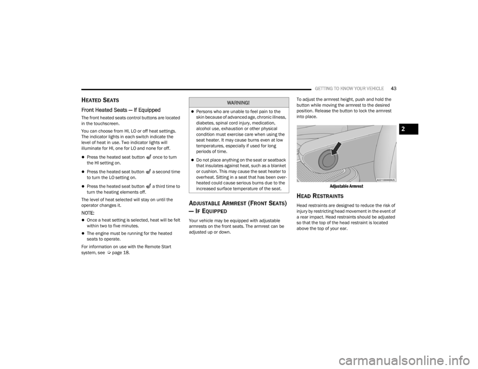
adjusted up or down. To adjust the armrest height, push and hold the
button while moving the armrest to the desired
position. Release the button to lock the armrest
into place.
Adjustable Armrest
HEAD RESTRAINTS
Head restraints are designed to reduce the risk of
injury by restricting head movement in the event of
a rear impact. Head restraints should be adjusted
so that the top of the head restraint is located
above the top of your ear.
WARNING!
Persons who are unable to feel pain to the
skin because of advanced age, chronic illness,
diabetes, spinal cord injury, medication,
alcohol use, exhaustion or other physical
condition must exercise care when using the
seat heater. It may cause burns even at low
temperatures, especially if used for long
periods of time.
Do not place anything on the seat or seatback
that insulates against heat, such as a blanket
or cushion. This may cause the seat heater to
overheat. Sitting in a seat that has been over -
heated could cause serious burns due to the
increased surface temperature of the seat.
2
21_RUV_OM_EN_USC_t.book Page 43
Page 88 of 348
86GETTING TO KNOW YOUR VEHICLE
(Continued)
NOTE:
To help control wind noise, stow the crossbars in
the side rails when they are not in use.
If any metallic object is placed over the satellite
radio antenna (if equipped), you may experience
interruption of satellite radio reception.
WARNING!
Cargo must be securely tied down before driving
your vehicle. Improperly secured loads can fly off
the vehicle, particularly at high speeds, resulting
in personal injury or property damage. Follow
the roof rack cautions when carrying cargo on
your roof rack.
CAUTION!
To prevent damage to the roof of your vehicle,
DO NOT carry any loads on the roof rack
without the crossbars deployed. The load
should be secured and placed on top of the
crossbars, not directly on the roof. If it is
necessary to place the load on the roof, place
a blanket or other protective layer between
the load and the roof surface.
To avoid damage to the roof rack and vehicle,
do not exceed the maximum roof rack load
capacity of 150 lb (68 kg). Always distribute
heavy loads as evenly as possible and secure
the load appropriately.
Load should always be secured to cross bars
first, with tie down loops used as additional
securing points if needed. Tie loops are
intended as supplementary tie down points
only. Do not use ratcheting mechanisms with
the tie loops. Check the straps and thumb
wheels frequently to be sure that the load
remains securely attached.
Long loads that extend over the windshield,
such as wood panels or surfboards, or loads
with large frontal area should be secured to
both the front and rear of the vehicle.
Travel at reduced speeds and turn corners
carefully when carrying large or heavy loads
on the roof rack. Wind forces, due to natural
causes or nearby truck traffic, can add sudden
upward lift to a load. This is especially true on
large flat loads and may result in damage to
the cargo or your vehicle.
CAUTION!
21_RUV_OM_EN_USC_t.book Page 86
Page 94 of 348
92GETTING TO KNOW YOUR INSTRUMENT PANEL
Coolant Temp
Displays the actual coolant temperature.
Transmission Temp
Displays the actual transmission temperature.
Oil Temp
Displays the actual oil temperature.
Oil Pressure
Displays the actual oil pressure.
Oil Life
Displays the remaining engine oil life as a
percentage.
To reset the Oil Life, you must hold the OK button.
The “Hold OK to Reset” instruction will be
displayed at all times, but the following conditions
will need to be met in order to reset Oil Life:
The ignition must be in the ON/RUN position
If the conditions are met, holding the OK button will
reset the gauge and the numeric display will return
to 100%.
If the conditions are not met, a pop-up message
will display for five seconds, describing the
required conditions, and then the Oil Life screen
will reappear.
Battery Voltage
Displays the actual battery voltage. Engine Hours — If Equipped
Displays the number of hours of engine operation.
Fuel Economy
Push and release the
up or down arrow
button until the Fuel Economy Menu item is
highlighted in the instrument cluster display. The
Fuel Economy Menu will display the following:
Two submenu pages that can be toggled
between using the left and right arrow
buttons; one with Current Value displayed and
one without the Current Value displayed:
Average Fuel Economy
(MPG, L/100 km, or km/L)
Range To Empty (miles or km)
Current Fuel Economy
(MPG, L/100 km, or km/L)
The Max and Min values will correspond to
the particular engine requirements
Hold OK to reset average fuel economy informa -
tion.
Trip Info
Push and release the up or down arrow
button until the Trip Menu item is highlighted in the
instrument cluster display. Push the left or
right arrow button to scroll through the Trip A and Trip B submenus. The Trip information will
display the following:
Distance
Average Fuel Economy
Elapsed Time
Hold the OK button to reset feature information.
Stop / Start – If Equipped
Push and release the up or down arrow
button until the Stop/Start menu title is displayed
in the instrument cluster display.
Audio
Push and release the up or down arrow
button until the Audio Menu displays in the
instrument cluster display.
Messages
Push and release the up or down arrow
button until Messages is highlighted in the
instrument cluster display. This feature shows the
number of stored warning messages. Pushing the
right arrow button will allow you to see what the
stored messages are.
NOTE:The pop-up messages indicate the status of the
system and/or the conditions that need to be met.
Messages remain in the stored stack until
condition is cleared.
21_RUV_OM_EN_USC_t.book Page 92
Page 103 of 348
GETTING TO KNOW YOUR INSTRUMENT PANEL101
Engine Check/Malfunction Indicator
Warning Light
The Engine Check/Malfunction Indicator
Light (MIL) is a part of an Onboard
Diagnostic System called OBD II that
monitors engine and automatic
transmission control systems. This warning light
will illuminate when the ignition is in the ON/RUN
position before engine start. If the bulb does not
come on when turning the ignition switch from
OFF to ON/RUN, have the condition checked
promptly.
Certain conditions, such as a loose or missing gas
cap, poor quality fuel, etc., may illuminate the light
after engine start. The vehicle should be serviced if
the light stays on through several typical driving
styles. In most situations, the vehicle will drive
normally and will not require towing.
When the engine is running, the MIL may flash to
alert serious conditions that could lead to
immediate loss of power or severe catalytic
converter damage. The vehicle should be serviced
by an authorized dealer as soon as possible if this
occurs.
Service Automatic Emergency Braking
(AEB) Warning Light — If Equipped
This warning light will illuminate to
indicate a fault in the AEB Warning
System. Contact an authorized dealer for
service
Úpage 196.
Service Stop/Start System Warning Light —
If Equipped
This warning light will illuminate when the
Stop/Start system is not functioning
properly and service is required. Contact
an authorized dealer for service
Úpage 119.
Tire Pressure Monitoring System (TPMS)
Warning Light
The warning light switches on and a
message is displayed to indicate that the
tire pressure is lower than the
recommended value and/or that slow
pressure loss is occurring. In these cases, optimal
tire duration and fuel consumption may not be
guaranteed.
Should one or more tires be in the condition
mentioned above, the display will show the
indications corresponding to each tire.
WARNING!
A malfunctioning catalytic converter, as
referenced above, can reach higher
temperatures than in normal operating
conditions. This can cause a fire if you drive
slowly or park over flammable substances such
as dry plants, wood, cardboard, etc. This could
result in death or serious injury to the driver,
occupants or others.
CAUTION!
Prolonged driving with the Malfunction Indicator
Light (MIL) on could cause damage to the
vehicle control system. It also could affect fuel
economy and driveability. If the MIL is flashing,
severe catalytic converter damage and power
loss will soon occur. Immediate service is
required.
CAUTION!
Do not continue driving with one or more flat
tires as handling may be compromised. Stop the
vehicle, avoiding sharp braking and steering. If a
tire puncture occurs, repair immediately using
the dedicated tire repair kit and contact an
authorized dealer as soon as possible.
3
21_RUV_OM_EN_USC_t.book Page 101
Page 104 of 348

102GETTING TO KNOW YOUR INSTRUMENT PANEL
Each tire, including the spare (if provided), should
be checked monthly when cold and inflated to the
inflation pressure recommended by the vehicle
manufacturer on the vehicle placard or tire
inflation pressure label. If your vehicle has tires of
a different size than the size indicated on the
vehicle placard or tire inflation pressure label, you
should determine the proper tire inflation pressure
for those tires.
As an added safety feature, your vehicle has been
equipped with a TPMS that illuminates a low tire
pressure telltale when one or more of your tires is
significantly underinflated. Accordingly, when the
low tire pressure telltale illuminates, you should
stop and check your tires as soon as possible, and
inflate them to the proper pressure. Driving on a
significantly underinflated tire causes the tire to
overheat and can lead to tire failure. Underinflation
also reduces fuel efficiency and tire tread life, and
may affect the vehicle’s handling and stopping
ability. Please note that the TPMS is not a substitute for
proper tire maintenance, and it is the driver’s
responsibility to maintain correct tire pressure,
even if underinflation has not reached the level to
trigger illumination of the TPMS low tire pressure
telltale.
Your vehicle has also been equipped with a TPMS
malfunction indicator to indicate when the system
is not operating properly. The TPMS malfunction
indicator is combined with the low tire pressure
telltale. When the system detects a malfunction,
the telltale will flash for approximately one minute
and then remain continuously illuminated. This
sequence will continue upon subsequent vehicle
start-ups as long as the malfunction exists. When
the malfunction indicator is illuminated, the
system may not be able to detect or signal low tire
pressure as intended. TPMS malfunctions may
occur for a variety of reasons, including the
installation of replacement or alternate tires or
wheels on the vehicle that prevent the TPMS from
functioning properly. Always check the TPMS
malfunction telltale after replacing one or more
tires or wheels on your vehicle to ensure that the
replacement or alternate tires and wheels allow
the TPMS to continue to function properly.
CAUTION!
The TPMS has been optimized for the original
equipment tires and wheels. TPMS pressures
and warning have been established for the tire
size equipped on your vehicle. Undesirable
system operation or sensor damage may result
when using replacement equipment that is not
of the same size, type, and/or style. Aftermarket
wheels can cause sensor damage. Using
aftermarket tire sealants may cause the Tire
Pressure Monitoring System (TPMS) sensor to
become inoperable. After using an aftermarket
tire sealant it is recommended that you take
your vehicle to an authorized dealer to have your
sensor function checked.
21_RUV_OM_EN_USC_t.book Page 102