fuel pressure CHRYSLER VOYAGER 2021 Owners Manual
[x] Cancel search | Manufacturer: CHRYSLER, Model Year: 2021, Model line: VOYAGER, Model: CHRYSLER VOYAGER 2021Pages: 348, PDF Size: 18.73 MB
Page 7 of 348
5
UCONNECT MODES ............................................. 159 Steering Wheel Audio Controls ................... 159
Radio Mode .................................................. 160
Media Mode .................................................. 168
Phone Mode ................................................. 170
ANDROID AUTO™ & APPLE CARPLAY® —
IF EQUIPPED ........................................................ 181
Android Auto™ .............................................. 181Apple CarPlay®.............................................. 183Android Auto™ And Apple CarPlay®
Tips And Tricks............................................... 185
RADIO OPERATION AND MOBILE PHONES ..... 185
Regulatory And Safety Information .............. 185
SAFETY
SAFETY FEATURES .............................................. 186Anti-Lock Brake System (ABS) ..................... 186
Electronic Brake Control (EBC) System ...... 187
AUXILIARY DRIVING SYSTEMS .......................... 192
Blind Spot Monitoring (BSM) —
If Equipped..................................................... 192
Forward Collision Warning (FCW)
With Mitigation — If Equipped....................... 196
Tire Pressure Monitoring System
(TPMS) ........................................................... 199 OCCUPANT RESTRAINT SYSTEMS ................... 202
Occupant Restraint Systems Features ....... 202
Important Safety Precautions ...................... 202Seat Belt Systems ........................................ 203Supplemental Restraint Systems (SRS) ...... 212Child Restraints ............................................ 225
SAFETY TIPS ...................................................... 241
Transporting Passengers .............................. 241Transporting Pets ........................................ 242Safety Checks You Should Make
Inside The Vehicle ........................................ 242Periodic Safety Checks You Should
Make Outside The Vehicle ............................ 243
Exhaust Gas ................................................. 244
Carbon Monoxide Warnings ........................ 244IN CASE OF EMERGENCY
HAZARD WARNING FLASHERS......................... 245
ASSIST AND SOS MIRROR —
IF EQUIPPED ....................................................... 245
JACKING AND TIRE CHANGING —
IF EQUIPPED ...................................................... 249
Preparations For Jacking ............................. 249
Jack And Spare Tire Location ....................... 250
Equipment Removal ..................................... 250
Jacking Instructions ..................................... 251
Road Tire Installation .................................... 254
Portable Air Compressor —
If Equipped..................................................... 255Return Inflatable Spare Tire ........................ 256 TIRE SERVICE KIT — IF EQUIPPED ..................... 257
JUMP STARTING .................................................. 262
Preparations For Jump Start ........................ 262Jump Starting Procedure .............................. 263
REFUELING IN EMERGENCY –
IF EQUIPPED ........................................................ 264
IF YOUR ENGINE OVERHEATS ............................ 265
MANUAL PARK RELEASE .................................. 266
FREEING A STUCK VEHICLE .............................. 267
TOWING A DISABLED VEHICLE ......................... 268
ENHANCED ACCIDENT RESPONSE
SYSTEM (EARS) ................................................... 270
EVENT DATA RECORDER (EDR) ......................... 270
SERVICING AND MAINTENANCE
SCHEDULED SERVICING .................................... 271 Maintenance Plan ......................................... 272
ENGINE COMPARTMENT ................................... 275
3.6L Engine ................................................... 275
Checking Oil Level ......................................... 276
Adding Washer Fluid .................................... 276
Maintenance-Free Battery ........................... 276
Pressure Washing ......................................... 277
21_RUV_OM_EN_USC_t.book Page 5
Page 12 of 348
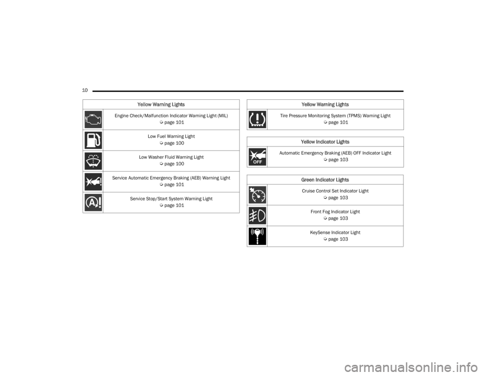
10 Engine Check/Malfunction Indicator Warning Light (MIL)
Úpage 101
Low Fuel Warning Light
Úpage 100
Low Washer Fluid Warning Light
Úpage 100
Service Automatic Emergency Braking (AEB) Warning Light
Úpage 101
Service Stop/Start System Warning Light
Úpage 101
Yellow Warning Lights
Tire Pressure Monitoring System (TPMS) Warning Light
Úpage 101
Yellow Indicator Lights
Automatic Emergency Braking (AEB) OFF Indicator Light
Úpage 103
Green Indicator Lights
Cruise Control Set Indicator Light
Úpage 103
Front Fog Indicator Light
Úpage 103
KeySense Indicator Light
Úpage 103
Yellow Warning Lights
21_RUV_OM_EN_USC_t.book Page 10
Page 93 of 348
GETTING TO KNOW YOUR INSTRUMENT PANEL91
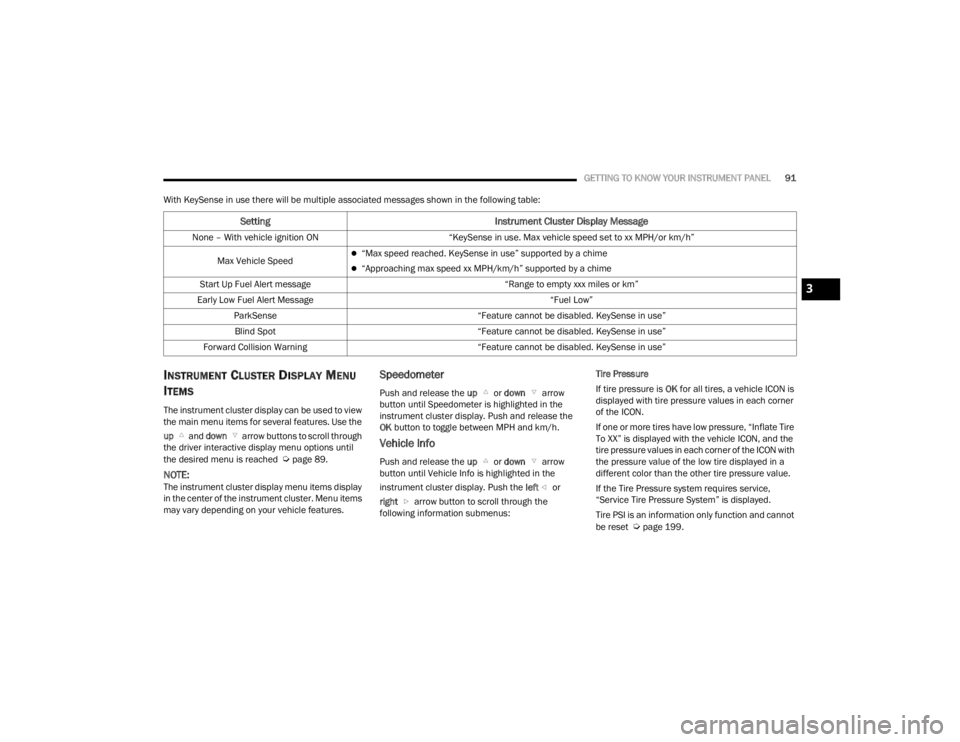
With KeySense in use there will be multiple associated messages shown in the following table:
INSTRUMENT CLUSTER DISPLAY MENU
I
TEMS
The instrument cluster display can be used to view
the main menu items for several features. Use the
up and down arrow buttons to scroll through
the driver interactive display menu options until
the desired menu is reached
Úpage 89.
NOTE:The instrument cluster display menu items display
in the center of the instrument cluster. Menu items
may vary depending on your vehicle features.
Speedometer
Push and release the up or down arrow
button until Speedometer is highlighted in the
instrument cluster display. Push and release the
OK button to toggle between MPH and km/h.
Vehicle Info
Push and release the up or down arrow
button until Vehicle Info is highlighted in the
instrument cluster display. Push the left or
right arrow button to scroll through the
following information submenus: Tire Pressure
If tire pressure is
OK for all tires, a vehicle ICON is
displayed with tire pressure values in each corner
of the ICON.
If one or more tires have low pressure, “Inflate Tire
To XX” is displayed with the vehicle ICON, and the
tire pressure values in each corner of the ICON with
the pressure value of the low tire displayed in a
different color than the other tire pressure value.
If the Tire Pressure system requires service,
“Service Tire Pressure System” is displayed.
Tire PSI is an information only function and cannot
be reset
Úpage 199.
Setting Instrument Cluster Display Message
None – With vehicle ignition ON “KeySense in use. Max vehicle speed set to xx MPH/or km/h”
Max Vehicle Speed
“Max speed reached. KeySense in use” supported by a chime
“Approaching max speed xx MPH/km/h” supported by a chime
Start Up Fuel Alert message “Range to empty xxx miles or km”
Early Low Fuel Alert Message “Fuel Low”
ParkSense “Feature cannot be disabled. KeySense in use”
Blind Spot “Feature cannot be disabled. KeySense in use”
Forward Collision Warning “Feature cannot be disabled. KeySense in use”
3
21_RUV_OM_EN_USC_t.book Page 91
Page 94 of 348
92GETTING TO KNOW YOUR INSTRUMENT PANEL
Coolant Temp
Displays the actual coolant temperature.
Transmission Temp
Displays the actual transmission temperature.
Oil Temp
Displays the actual oil temperature.
Oil Pressure
Displays the actual oil pressure.
Oil Life
Displays the remaining engine oil life as a
percentage.
To reset the Oil Life, you must hold the OK button.
The “Hold OK to Reset” instruction will be
displayed at all times, but the following conditions
will need to be met in order to reset Oil Life:
The ignition must be in the ON/RUN position
If the conditions are met, holding the OK button will
reset the gauge and the numeric display will return
to 100%.
If the conditions are not met, a pop-up message
will display for five seconds, describing the
required conditions, and then the Oil Life screen
will reappear.
Battery Voltage
Displays the actual battery voltage. Engine Hours — If Equipped
Displays the number of hours of engine operation.
Fuel Economy
Push and release the
up or down arrow
button until the Fuel Economy Menu item is
highlighted in the instrument cluster display. The
Fuel Economy Menu will display the following:
Two submenu pages that can be toggled
between using the left and right arrow
buttons; one with Current Value displayed and
one without the Current Value displayed:
Average Fuel Economy
(MPG, L/100 km, or km/L)
Range To Empty (miles or km)
Current Fuel Economy
(MPG, L/100 km, or km/L)
The Max and Min values will correspond to
the particular engine requirements
Hold OK to reset average fuel economy informa -
tion.
Trip Info
Push and release the up or down arrow
button until the Trip Menu item is highlighted in the
instrument cluster display. Push the left or
right arrow button to scroll through the Trip A and Trip B submenus. The Trip information will
display the following:
Distance
Average Fuel Economy
Elapsed Time
Hold the OK button to reset feature information.
Stop / Start – If Equipped
Push and release the up or down arrow
button until the Stop/Start menu title is displayed
in the instrument cluster display.
Audio
Push and release the up or down arrow
button until the Audio Menu displays in the
instrument cluster display.
Messages
Push and release the up or down arrow
button until Messages is highlighted in the
instrument cluster display. This feature shows the
number of stored warning messages. Pushing the
right arrow button will allow you to see what the
stored messages are.
NOTE:The pop-up messages indicate the status of the
system and/or the conditions that need to be met.
Messages remain in the stored stack until
condition is cleared.
21_RUV_OM_EN_USC_t.book Page 92
Page 103 of 348
GETTING TO KNOW YOUR INSTRUMENT PANEL101
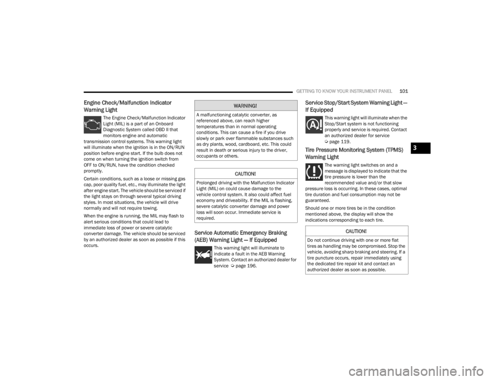
Engine Check/Malfunction Indicator
Warning Light
The Engine Check/Malfunction Indicator
Light (MIL) is a part of an Onboard
Diagnostic System called OBD II that
monitors engine and automatic
transmission control systems. This warning light
will illuminate when the ignition is in the ON/RUN
position before engine start. If the bulb does not
come on when turning the ignition switch from
OFF to ON/RUN, have the condition checked
promptly.
Certain conditions, such as a loose or missing gas
cap, poor quality fuel, etc., may illuminate the light
after engine start. The vehicle should be serviced if
the light stays on through several typical driving
styles. In most situations, the vehicle will drive
normally and will not require towing.
When the engine is running, the MIL may flash to
alert serious conditions that could lead to
immediate loss of power or severe catalytic
converter damage. The vehicle should be serviced
by an authorized dealer as soon as possible if this
occurs.
Service Automatic Emergency Braking
(AEB) Warning Light — If Equipped
This warning light will illuminate to
indicate a fault in the AEB Warning
System. Contact an authorized dealer for
service
Úpage 196.
Service Stop/Start System Warning Light —
If Equipped
This warning light will illuminate when the
Stop/Start system is not functioning
properly and service is required. Contact
an authorized dealer for service
Úpage 119.
Tire Pressure Monitoring System (TPMS)
Warning Light
The warning light switches on and a
message is displayed to indicate that the
tire pressure is lower than the
recommended value and/or that slow
pressure loss is occurring. In these cases, optimal
tire duration and fuel consumption may not be
guaranteed.
Should one or more tires be in the condition
mentioned above, the display will show the
indications corresponding to each tire.
WARNING!
A malfunctioning catalytic converter, as
referenced above, can reach higher
temperatures than in normal operating
conditions. This can cause a fire if you drive
slowly or park over flammable substances such
as dry plants, wood, cardboard, etc. This could
result in death or serious injury to the driver,
occupants or others.
CAUTION!
Prolonged driving with the Malfunction Indicator
Light (MIL) on could cause damage to the
vehicle control system. It also could affect fuel
economy and driveability. If the MIL is flashing,
severe catalytic converter damage and power
loss will soon occur. Immediate service is
required.
CAUTION!
Do not continue driving with one or more flat
tires as handling may be compromised. Stop the
vehicle, avoiding sharp braking and steering. If a
tire puncture occurs, repair immediately using
the dedicated tire repair kit and contact an
authorized dealer as soon as possible.
3
21_RUV_OM_EN_USC_t.book Page 101
Page 104 of 348

102GETTING TO KNOW YOUR INSTRUMENT PANEL
Each tire, including the spare (if provided), should
be checked monthly when cold and inflated to the
inflation pressure recommended by the vehicle
manufacturer on the vehicle placard or tire
inflation pressure label. If your vehicle has tires of
a different size than the size indicated on the
vehicle placard or tire inflation pressure label, you
should determine the proper tire inflation pressure
for those tires.
As an added safety feature, your vehicle has been
equipped with a TPMS that illuminates a low tire
pressure telltale when one or more of your tires is
significantly underinflated. Accordingly, when the
low tire pressure telltale illuminates, you should
stop and check your tires as soon as possible, and
inflate them to the proper pressure. Driving on a
significantly underinflated tire causes the tire to
overheat and can lead to tire failure. Underinflation
also reduces fuel efficiency and tire tread life, and
may affect the vehicle’s handling and stopping
ability. Please note that the TPMS is not a substitute for
proper tire maintenance, and it is the driver’s
responsibility to maintain correct tire pressure,
even if underinflation has not reached the level to
trigger illumination of the TPMS low tire pressure
telltale.
Your vehicle has also been equipped with a TPMS
malfunction indicator to indicate when the system
is not operating properly. The TPMS malfunction
indicator is combined with the low tire pressure
telltale. When the system detects a malfunction,
the telltale will flash for approximately one minute
and then remain continuously illuminated. This
sequence will continue upon subsequent vehicle
start-ups as long as the malfunction exists. When
the malfunction indicator is illuminated, the
system may not be able to detect or signal low tire
pressure as intended. TPMS malfunctions may
occur for a variety of reasons, including the
installation of replacement or alternate tires or
wheels on the vehicle that prevent the TPMS from
functioning properly. Always check the TPMS
malfunction telltale after replacing one or more
tires or wheels on your vehicle to ensure that the
replacement or alternate tires and wheels allow
the TPMS to continue to function properly.
CAUTION!
The TPMS has been optimized for the original
equipment tires and wheels. TPMS pressures
and warning have been established for the tire
size equipped on your vehicle. Undesirable
system operation or sensor damage may result
when using replacement equipment that is not
of the same size, type, and/or style. Aftermarket
wheels can cause sensor damage. Using
aftermarket tire sealants may cause the Tire
Pressure Monitoring System (TPMS) sensor to
become inoperable. After using an aftermarket
tire sealant it is recommended that you take
your vehicle to an authorized dealer to have your
sensor function checked.
21_RUV_OM_EN_USC_t.book Page 102
Page 132 of 348
130STARTING AND OPERATING
Payload
The payload of a vehicle is defined as the allowable
load weight a truck can carry, including the weight
of the driver, all passengers, options and cargo.
Gross Axle Weight Rating (GAWR)
The GAWR is the maximum permissible load on the
front and rear axles. The load must be distributed
in the cargo area so that the GAWR of each axle is
not exceeded.
Each axle GAWR is determined by the components
in the system with the lowest load carrying capacity
(axle, springs, tires or wheels). Heavier axles or
suspension components sometimes specified by
purchasers for increased durability does not
necessarily increase the vehicle's GVWR.
Tire Size
The tire size on the Vehicle Certification Label
represents the actual tire size on your vehicle.
Replacement tires must be equal to the load
capacity of this tire size.
Rim Size
This is the rim size that is appropriate for the tire
size listed.
Inflation Pressure
This is the cold tire inflation pressure for your
vehicle for all loading conditions up to full GAWR.
Curb Weight
The curb weight of a vehicle is defined as the total
weight of the vehicle with all fluids, including
vehicle fuel, at full capacity conditions, and with no
occupants or cargo loaded into the vehicle. The
front and rear curb weight values are determined
by weighing your vehicle on a commercial scale
before any occupants or cargo are added.
Loading
The actual total weight and the weight of the front
and rear of your vehicle at the ground can best be
determined by weighing it when it is loaded and
ready for operation.
The entire vehicle should first be weighed on a
commercial scale to ensure that the GVWR has not
been exceeded. The weight on the front and rear of
the vehicle should then be determined separately
to be sure that the load is properly distributed over
the front and rear axle. Weighing the vehicle may
show that the GAWR of either the front or rear axles
has been exceeded but the total load is within the
specified GVWR. If so, weight must be shifted from
front to rear or rear to front as appropriate until the
specified weight limitations are met. Store the
heavier items down low and be sure that the
weight is distributed equally. Stow all loose items
securely before driving. Improper weight distributions can have an adverse
effect on the way your vehicle steers and handles
and the way the brakes operate.
TRAILER TOWING
In this section you will find safety tips and
information on limits to the type of towing you can
reasonably do with your vehicle. Before towing a
trailer, carefully review this information to tow your
load as efficiently and safely as possible.
To maintain the New Vehicle Limited Warranty
coverage, follow the requirements and
recommendations in this manual concerning
vehicles used for trailer towing.
COMMON TOWING DEFINITIONS
The following trailer towing related definitions will
assist you in understanding the following
information:
CAUTION!
Do not load your vehicle any heavier than the
GVWR or the maximum front and rear GAWR. If
you do, parts on your vehicle can break, or it can
change the way your vehicle handles. This could
cause you to lose control. Also overloading can
shorten the life of your vehicle.
21_RUV_OM_EN_USC_t.book Page 130
Page 148 of 348

146MULTIMEDIA
Units
Voice
When the Units button is pressed on the touchscreen, the system displays the different measurement options. The selected unit of measurement will display
in the instrument cluster display and Navigation system (if equipped). The available settings are:
Setting Name Description
USThis setting will change the unit of measurement on the display to US.
Metric This setting will change the unit of measurement on the display to Metric.
Custom This setting changes the “Speed” (MPH or km/h), “Distance” (mi or km), “Fuel Consumption”
(MPG [US], MPG [UK], L/100 km, or km/L), “Pressure” (psi, kPa, or bar), “Temperature” (°C or °F), and
“Capacity” (Gal [US], Gal [UK], or L) units of measurement independently.
When the Voice button is pressed on the touchscreen, the system displays the options related to the vehicle’s Voice Recognition feature.
Setting Name
Description
Voice Response LengthThis setting will change the response length for the Voice Recognition system. The “Brief” setting
provides a shortened audio description from the system. The “Detailed” setting provides the full audio
description from the system.
Show Command List This setting will allow you to turn the Command List on or off. The “Always” setting will always show the
Command List. The “With Help” setting will show the Command List and provide a brief description of
what the command does. The “Never” setting will turn the Command List off.
21_RUV_OM_EN_USC_t.book Page 146
Page 202 of 348

200SAFETY
NOTE:
The TPMS is not intended to replace normal tire
care and maintenance, or to provide warning of
a tire failure or condition.
The TPMS should not be used as a tire pressure
gauge while adjusting your tire pressure.
Driving on a significantly underinflated tire
causes the tire to overheat and can lead to tire
failure. Underinflation also reduces fuel effi -
ciency and tire tread life, and may affect the
vehicle’s handling and stopping ability.
The TPMS is not a substitute for proper tire
maintenance, and it is the driver’s responsibility
to maintain correct tire pressure using an accu -
rate tire pressure gauge, even if underinflation
has not reached the level to trigger illumination
of the TPMS Warning Light.
Seasonal temperature changes will affect tire
pressure, and the TPMS will monitor the actual
tire pressure in the tire.
Premium System
The Tire Pressure Monitoring System (TPMS) uses
wireless technology with wheel rim mounted
electronic sensors to monitor tire pressure levels.
Sensors, mounted to each wheel as part of the
valve stem, transmit tire pressure readings to the
receiver module.
NOTE:It is particularly important for you to check the tire
pressure in all of the tires on your vehicle monthly
and to maintain the proper pressure.
The TPMS consists of the following components:
Receiver module
Four Tire Pressure Monitoring System sensors
Various Tire Pressure Monitoring System
messages, which display in the instrument
cluster
Tire Pressure Monitoring System Warning Light
SERVICE TPMS WARNING
When a system fault is detected, the Tire Pressure
Monitoring System (TPMS) Warning Light will flash
on and off for 75 seconds and then remain on
solid. The system fault will also sound a chime. In
addition, the instrument cluster will display a
"SERVICE TPM SYSTEM" message for a minimum
of five seconds and then display dashes (--) in
place of the pressure value to indicate which
sensor is not being received.
CAUTION!
The TPMS has been optimized for the original
equipment tires and wheels. TPMS pressures
and warning have been established for the tire
size equipped on your vehicle. Undesirable
system operation or sensor damage may
result when using replacement equipment
that is not of the same size, type, and/or style.
The TPMS sensor is not designed for use on
aftermarket wheels and may contribute to a
poor overall system performance or sensor
damage. Customers are encouraged to use
OEM wheels to ensure proper TPMS feature
operation.
Using aftermarket tire sealants may cause the
Tire Pressure Monitoring System (TPMS)
sensor to become inoperable. After using an
aftermarket tire sealant it is recommended
that you take your vehicle to an authorized
dealer to have your sensor function checked.
After inspecting or adjusting the tire pressure
always reinstall the valve stem cap. This will
prevent moisture and dirt from entering the
valve stem, which could damage the TPMS
sensor.
21_RUV_OM_EN_USC_t.book Page 200
Page 245 of 348
SAFETY243
(Continued)
PERIODIC SAFETY CHECKS YOU SHOULD
M
AKE OUTSIDE THE VEHICLE
Tires
Examine tires for excessive tread wear and uneven
wear patterns. Check for stones, nails, glass, or
other objects lodged in the tread or sidewall.
Inspect the tread for cuts and cracks. Inspect
sidewalls for cuts, cracks, and bulges. Check the
lug nut/bolt torque for tightness. Check the tires
(including spare) for proper cold inflation pressure.
Lights
Have someone observe the operation of brake
lights and exterior lights while you work the
controls. Check turn signal and high beam
indicator lights on the instrument panel.
Door Latches
Check for proper closing, latching, and locking.
Fluid Leaks
Check area under the vehicle after overnight
parking for fuel, coolant, oil, or other fluid leaks.
Also, if gasoline fumes are detected or if fuel or
brake fluid leaks are suspected, the cause should
be located and corrected immediately.
ALWAYS REMOVE THE EXISTING FLOOR MAT
FROM THE VEHICLE before installing any
other floor mat. NEVER install or stack an
additional floor mat on top of an existing floor
mat.
ONLY install floor mats designed to fit your
vehicle. NEVER install a floor mat that cannot
be properly attached and secured to your
vehicle. If a floor mat needs to be replaced,
only use a FCA approved floor mat for the
specific make, model, and year of your
vehicle.
ONLY use the driver’s side floor mat on the
driver’s side floor area. To check for interfer -
ence, with the vehicle properly parked with the
engine off, fully depress the accelerator, the
brake, and the clutch pedal (if present) to
check for interference. If your floor mat inter -
feres with the operation of any pedal, or is not
secure to the floor, remove the floor mat from
the vehicle and place the floor mat in your
trunk.
ONLY use the passenger’s side floor mat on
the passenger’s side floor area.
WARNING!
ALWAYS make sure objects cannot fall or slide
into the driver’s side floor area when the
vehicle is moving. Objects can become
trapped under accelerator, brake, or clutch
pedals and could cause a loss of vehicle
control.
NEVER place any objects under the floor mat
(e.g., towels, keys, etc.). These objects could
change the position of the floor mat and may
cause interference with the accelerator,
brake, or clutch pedals.
If the vehicle carpet has been removed and
re-installed, always properly attach carpet to
the floor and check the floor mat fasteners are
secure to the vehicle carpet. Fully depress
each pedal to check for interference with the
accelerator, brake, or clutch pedals then
re-install the floor mats.
It is recommended to only use mild soap and
water to clean your floor mats. After cleaning,
always check your floor mat has been properly
installed and is secured to your vehicle using
the floor mat fasteners by lightly pulling mat.
WARNING!
6
21_RUV_OM_EN_USC_t.book Page 243