oil temperature CHRYSLER VOYAGER 2021 Owners Manual
[x] Cancel search | Manufacturer: CHRYSLER, Model Year: 2021, Model line: VOYAGER, Model: CHRYSLER VOYAGER 2021Pages: 348, PDF Size: 18.73 MB
Page 5 of 348
3
EXTERIOR LIGHTS ................................................. 53 Multifunction Lever .........................................53
Headlight Switch...............................................53
Daytime Running Lights (DRLs) —
If Equipped........................................................54
High/Low Beam Switch....................................54
Flash-To-Pass ...................................................54
Automatic Headlights — If Equipped ..............54
Headlight Time Delay — If Equipped ...............54
Lights-On Reminder..........................................54
Front Fog Lights — If Equipped .......................54
Turn Signals ......................................................55
Lane Change Assist — If Equipped ..................55
Battery Protection ...........................................55
INTERIOR LIGHTS ................................................. 55
Interior Courtesy Lights ...................................55
WINDSHIELD WIPER AND WASHERS ............... 56
Windshield Wiper Operation .........................57
Rear Wiper And Washer ...................................58
CLIMATE CONTROLS ........................................... 58
Automatic Climate Control Descriptions
And Functions ...................................................58
Manual Climate Control Descriptions
And Functions ...................................................64
Automatic Temperature Control (ATC) —
If Equipped .......................................................69
Climate Voice Commands................................70
Operating Tips .................................................70 INTERIOR STORAGE AND EQUIPMENT ............... 71
Storage..............................................................71
Sun Screens — If Equipped..............................74
USB/AUX Control ...........................................75
Power Outlets ..................................................76
Cigar Lighter — If Equipped .............................78
Smoker's Package Kit — If Equipped .............78
WINDOWS ...............................................................78
Power Windows ................................................78
Automatic Window Features ...........................79
Reset Auto Up...................................................79
Wind Buffeting ..................................................80
HOOD .....................................................................80
Opening.............................................................80
Closing ..............................................................80
LIFTGATE ................................................................. 81
To Unlock/Open The Liftgate...........................81
To Lock/Close The Liftgate ..............................81
Power Liftgate — If Equipped ...........................81
Cargo Area Features .......................................82
STOW ‘N PLACE ROOF RACK —
IF EQUIPPED .......................................................... 83
Deploying The Crossbars .................................83
Stowing The Crossbars ....................................84
GETTING TO KNOW YOUR
INSTRUMENT PANEL
INSTRUMENT CLUSTER......................................... 87Instrument Cluster Descriptions ..................... 88
INSTRUMENT CLUSTER DISPLAY ....................... 88
Instrument Cluster Display Location And
Controls............................................................. 89
Oil Life Reset ................................................... 90
KeySense Cluster Messages —
If Equipped .......................................................90
Instrument Cluster Display Menu Items ........ 91
Battery Saver On/Battery Saver Mode
Message — Electrical Load Reduction
Actions — If Equipped ...................................... 95
TRIP COMPUTER ................................................... 96
WARNING LIGHTS AND MESSAGES ................... 97
Red Warning Lights ..........................................97
Yellow Warning Lights ................................... 100
Yellow Indicator Lights .................................. 103 Green Indicator Lights .................................. 103White Indicator Lights ................................... 103
Blue Indicator Lights ..................................... 103
ONBOARD DIAGNOSTIC SYSTEM — OBD II ..... 104
Onboard Diagnostic System
(OBD II) Cybersecurity ................................... 104
EMISSIONS INSPECTION AND MAINTENANCE
PROGRAMS ......................................................... 105
21_RUV_OM_EN_USC_t.book Page 3
Page 8 of 348
6
VEHICLE MAINTENANCE .................................... 277 Engine Oil ...................................................... 277Engine Oil Filter ............................................ 278
Engine Air Cleaner Filter ............................. 278
Accessory Drive Belt Inspection ................... 279
Air Conditioner Maintenance ....................... 279
Body Lubrication ........................................... 282Windshield Wiper Blades ............................. 282
Exhaust System ............................................ 285
Cooling System .............................................. 286Brake System ............................................... 289
Automatic Transmission .............................. 290FUSES............................................................. 290
BULB REPLACEMENT ................................... 299
TIRES .................................................................... 301
Tire Safety Information ............................... 301
Tires — General Information ........................ 309
Tire Types ....................................................... 313
Spare Tires — If Equipped ........................... 313
Wheel And Wheel Trim Care ....................... 315
Snow Traction Devices ................................. 316Tire Rotation Recommendations ................. 317
DEPARTMENT OF TRANSPORTATION
UNIFORM TIRE QUALITY GRADES .................... 318
Treadwear ...................................................... 318Traction Grades ............................................. 318
Temperature Grades ..................................... 318
STORING THE VEHICLE ....................................... 319 BODYWORK ......................................................... 319
Protection From Atmospheric Agents ......... 319Body And Underbody Maintenance.............. 319Preserving The Bodywork ............................. 319
INTERIORS .......................................................... 320
Seats And Fabric Parts ................................. 320
Plastic And Coated Parts .............................. 321Leather Surfaces ........................................... 321Glass Surfaces ............................................. 321
TECHNICAL SPECIFICATIONS
VEHICLE IDENTIFICATION NUMBER (VIN) ........ 322
BRAKE SYSTEM ................................................... 322
WHEEL AND TIRE TORQUE
SPECIFICATIONS ................................................ 322
Torque Specifications ................................... 322
FUEL REQUIREMENTS ....................................... 323
3.6L Engine .................................................. 323
Reformulated Gasoline .............................. 324Gasoline/Oxygenate Blends ........................ 324
Do Not Use E-85 In Non-Flex Fuel
Vehicles.......................................................... 324CNG And LP Fuel System Modifications ...... 324Methylcyclopentadienyl Manganese
Tricarbonyl (MMT) In Gasoline...................... 324Materials Added To Fuel .............................. 325Fuel System Cautions ................................... 325
FLUID CAPACITIES ............................................ 326
ENGINE FLUIDS AND LUBRICANTS .................. 326
CHASSIS FLUIDS AND LUBRICANTS ............... 327
CUSTOMER ASSISTANCE
SUGGESTIONS FOR OBTAINING
SERVICE FOR YOUR VEHICLE ............................ 328
Prepare For The Appointment ...................... 328
Prepare A List ................................................ 328
Be Reasonable With Requests..................... 328
IF YOU NEED ASSISTANCE ................................ 328
FCA US LLC Customer Center....................... 328
FCA Canada Inc. Customer Center .............. 328
Mexico............................................................ 329
Puerto Rico And US Virgin Islands ............... 329
Customer Assistance For The Hearing
Or Speech Impaired
(TDD/TTY) ...................................................... 329
Service Contract ........................................... 329
WARRANTY INFORMATION ................................ 330
MOPAR® PARTS ................................................. 330
REPORTING SAFETY DEFECTS .......................... 330
In The 50 United States And
Washington, D.C............................................ 330
In Canada ...................................................... 330
PUBLICATION ORDER FORMS .......................... 331
GENERAL INFORMATION.................................... 331
21_RUV_OM_EN_USC_t.book Page 6
Page 11 of 348
9
Door Open Warning Light
Úpage 98
Electric Power Steering Fault Warning Light
Úpage 98
Electronic Throttle Control (ETC) Warning Light
Úpage 98
Engine Coolant Temperature Warning Light
Úpage 98
Hood Open Warning Light
Úpage 99
Liftgate Open Warning Light
Úpage 99
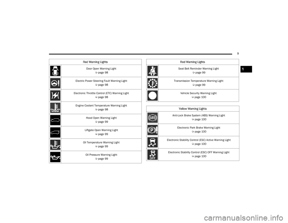
Oil Temperature Warning Light
Úpage 99
Oil Pressure Warning Light
Úpage 99
Red Warning Lights
Seat Belt Reminder Warning Light
Úpage 99
Transmission Temperature Warning Light
Úpage 99
Vehicle Security Warning Light
Úpage 100
Yellow Warning Lights
Anti-Lock Brake System (ABS) Warning Light
Úpage 100
Electronic Park Brake Warning Light
Úpage 100
Electronic Stability Control (ESC) Active Warning Light
Úpage 100
Electronic Stability Control (ESC) OFF Warning Light
Úpage 100
Red Warning Lights
1
21_RUV_OM_EN_USC_t.book Page 9
Page 90 of 348
88GETTING TO KNOW YOUR INSTRUMENT PANEL
INSTRUMENT CLUSTER DESCRIPTIONS
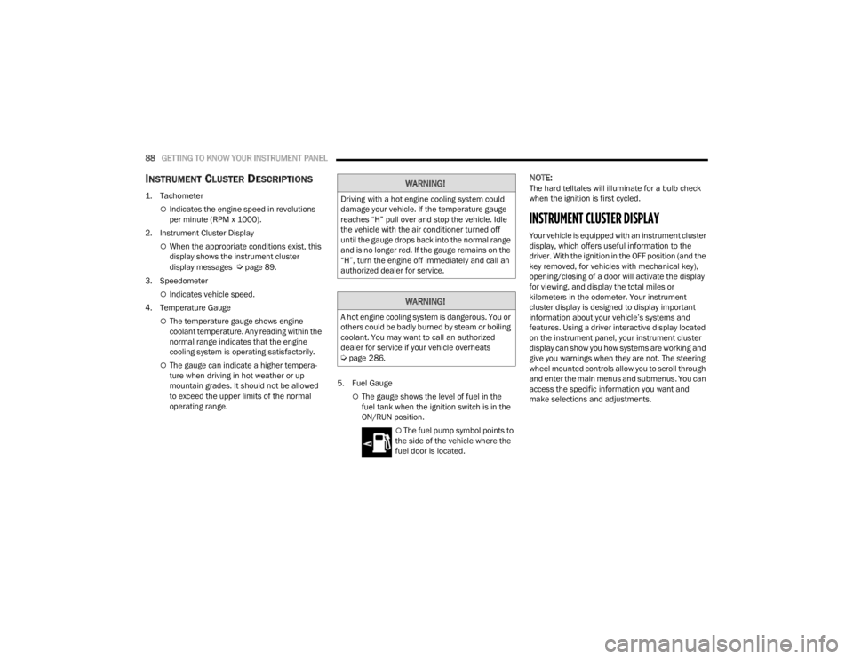
1. Tachometer
Indicates the engine speed in revolutions
per minute (RPM x 1000).
2. Instrument Cluster Display
When the appropriate conditions exist, this
display shows the instrument cluster
display messages
Úpage 89.
3. Speedometer
Indicates vehicle speed.
4. Temperature Gauge
The temperature gauge shows engine
coolant temperature. Any reading within the
normal range indicates that the engine
cooling system is operating satisfactorily.
The gauge can indicate a higher tempera -
ture when driving in hot weather or up
mountain grades. It should not be allowed
to exceed the upper limits of the normal
operating range. 5. Fuel Gauge
The gauge shows the level of fuel in the
fuel tank when the ignition switch is in the
ON/RUN position.
The fuel pump symbol points to
the side of the vehicle where the
fuel door is located.
NOTE:The hard telltales will illuminate for a bulb check
when the ignition is first cycled.
INSTRUMENT CLUSTER DISPLAY
Your vehicle is equipped with an instrument cluster
display, which offers useful information to the
driver. With the ignition in the OFF position (and the
key removed, for vehicles with mechanical key),
opening/closing of a door will activate the display
for viewing, and display the total miles or
kilometers in the odometer. Your instrument
cluster display is designed to display important
information about your vehicle’s systems and
features. Using a driver interactive display located
on the instrument panel, your instrument cluster
display can show you how systems are working and
give you warnings when they are not. The steering
wheel mounted controls allow you to scroll through
and enter the main menus and submenus. You can
access the specific information you want and
make selections and adjustments.
WARNING!
Driving with a hot engine cooling system could
damage your vehicle. If the temperature gauge
reaches “H” pull over and stop the vehicle. Idle
the vehicle with the air conditioner turned off
until the gauge drops back into the normal range
and is no longer red. If the gauge remains on the
“H”, turn the engine off immediately and call an
authorized dealer for service.
WARNING!
A hot engine cooling system is dangerous. You or
others could be badly burned by steam or boiling
coolant. You may want to call an authorized
dealer for service if your vehicle overheats
Úpage 286.
21_RUV_OM_EN_USC_t.book Page 88
Page 94 of 348
92GETTING TO KNOW YOUR INSTRUMENT PANEL
Coolant Temp
Displays the actual coolant temperature.
Transmission Temp
Displays the actual transmission temperature.
Oil Temp
Displays the actual oil temperature.
Oil Pressure
Displays the actual oil pressure.
Oil Life
Displays the remaining engine oil life as a
percentage.
To reset the Oil Life, you must hold the OK button.
The “Hold OK to Reset” instruction will be
displayed at all times, but the following conditions
will need to be met in order to reset Oil Life:
The ignition must be in the ON/RUN position
If the conditions are met, holding the OK button will
reset the gauge and the numeric display will return
to 100%.
If the conditions are not met, a pop-up message
will display for five seconds, describing the
required conditions, and then the Oil Life screen
will reappear.
Battery Voltage
Displays the actual battery voltage. Engine Hours — If Equipped
Displays the number of hours of engine operation.
Fuel Economy
Push and release the
up or down arrow
button until the Fuel Economy Menu item is
highlighted in the instrument cluster display. The
Fuel Economy Menu will display the following:
Two submenu pages that can be toggled
between using the left and right arrow
buttons; one with Current Value displayed and
one without the Current Value displayed:
Average Fuel Economy
(MPG, L/100 km, or km/L)
Range To Empty (miles or km)
Current Fuel Economy
(MPG, L/100 km, or km/L)
The Max and Min values will correspond to
the particular engine requirements
Hold OK to reset average fuel economy informa -
tion.
Trip Info
Push and release the up or down arrow
button until the Trip Menu item is highlighted in the
instrument cluster display. Push the left or
right arrow button to scroll through the Trip A and Trip B submenus. The Trip information will
display the following:
Distance
Average Fuel Economy
Elapsed Time
Hold the OK button to reset feature information.
Stop / Start – If Equipped
Push and release the up or down arrow
button until the Stop/Start menu title is displayed
in the instrument cluster display.
Audio
Push and release the up or down arrow
button until the Audio Menu displays in the
instrument cluster display.
Messages
Push and release the up or down arrow
button until Messages is highlighted in the
instrument cluster display. This feature shows the
number of stored warning messages. Pushing the
right arrow button will allow you to see what the
stored messages are.
NOTE:The pop-up messages indicate the status of the
system and/or the conditions that need to be met.
Messages remain in the stored stack until
condition is cleared.
21_RUV_OM_EN_USC_t.book Page 92
Page 101 of 348
GETTING TO KNOW YOUR INSTRUMENT PANEL99
If the light turns on while driving, safely pull over
and stop the vehicle. If the Air Conditioning (A/C)
system is on, turn it off. Also, shift the transmission
into NEUTRAL (N) and idle the vehicle. If the
temperature reading does not return to normal,
turn the engine off immediately and call for service
Úpage 265.
Hood Open Warning Light
This warning light will illuminate when the
hood is left open and not fully closed.
NOTE:If the vehicle is moving, there will also be a single
chime.
Liftgate Open Warning Light
This warning light will illuminate when the
liftgate is open.
NOTE:If the vehicle is moving, there will also be a single
chime.
Oil Pressure Warning Light
This warning light will illuminate to
indicate low engine oil pressure. If the
light turns on while driving, stop the
vehicle, shut off the engine as soon as
possible, and contact an authorized dealer.
A chime will sound when this light turns on.
Do not operate the vehicle until the cause is
corrected. This light does not indicate how much oil
is in the engine. The engine oil level must be
checked under the hood.
Oil Temperature Warning Light
This warning light will illuminate to
indicate the engine oil temperature is
high. If the light turns on while driving,
stop the vehicle and shut off the engine
as soon as possible. Wait for oil temperature to
return to normal levels.
Seat Belt Reminder Warning Light
This warning light indicates when the
driver or passenger seat belt is
unbuckled. When the ignition is first
placed in the ON/RUN or ACC/ON/RUN
position and if the driver’s seat belt is unbuckled,
a chime will sound and the light will turn on. When
driving, if the driver or front passenger seat belt
remains unbuckled, the Seat Belt Reminder Light
will flash or remain on continuously and a chime
will sound
Úpage 202.
Transmission Temperature Warning
Light — If Equipped
This warning light will illuminate to warn
of a high transmission fluid temperature.
This may occur with strenuous usage
such as trailer towing. If this light turns
on, stop the vehicle and run the engine at idle or
slightly faster, with the transmission in PARK (P) or
NEUTRAL (N), until the light turns off. Once the light
turns off, you may continue to drive normally.
WARNING!
If you continue operating the vehicle when the
Transmission Temperature Warning Light is
illuminated you could cause the fluid to boil over,
come in contact with hot engine or exhaust
components and cause a fire.
CAUTION!
Continuous driving with the Transmission
Temperature Warning Light illuminated will
eventually cause severe transmission damage
or transmission failure.
3
21_RUV_OM_EN_USC_t.book Page 99
Page 273 of 348
271
SERVICING AND MAINTENANCE
SCHEDULED SERVICING
Your vehicle is equipped with an automatic oil
change indicator system. The oil change indicator
system will remind you that it is time to take your
vehicle in for scheduled maintenance.
Based on engine operation conditions, the oil
change indicator message will illuminate. This
means that service is required for your vehicle.
Operating conditions such as frequent short-trips,
trailer tow, extremely hot or cold ambient
temperatures will influence when the “Oil Change
Required” message is displayed. Have your vehicle
serviced as soon as possible, within the next
500 miles (805 km).An authorized dealer will reset the oil change
indicator message after completing the scheduled
oil change. If a scheduled oil change is performed
by someone other than an authorized dealer
Úpage 89.
NOTE:Under no circumstances should oil change
intervals exceed 10,000 miles (16,000 km),
12 months or 350 hours of engine run time,
whichever comes first. The 350 hours of engine
run or idle time is generally only a concern for fleet
customers.
Once A Month Or Before A Long Trip:
Check engine oil level
Check windshield washer fluid level
Check tire pressure and look for unusual wear
or damage. Rotate tires at the first sign of irreg
-
ular wear, even if it occurs before the oil indi -
cator system turns on
Check the fluid levels of the coolant reservoir
and brake master cylinder, fill as needed
Check function of all interior and exterior lights
8
21_RUV_OM_EN_USC_t.book Page 271
Page 278 of 348
276SERVICING AND MAINTENANCE
(Continued)
CHECKING OIL LEVEL
To ensure proper engine lubrication, the engine oil
must be maintained at the correct level. Check the
oil level at regular intervals, such as every fuel
stop. The best time to check the engine oil level is
about five minutes after a fully warmed up engine
is shut off.
Checking the oil while the vehicle is on level ground
will improve the accuracy of the oil level readings.
There are four possible dipstick types:
Crosshatched zone.
Crosshatched zone marked SAFE.
Crosshatched zone marked with MIN at the low
end of the range and MAX at the high end of the
range.
Crosshatched zone marked with dimples at the
MIN and the MAX ends of the range.
NOTE:Always maintain the oil level within the crosshatch
markings on the dipstick.
Adding 1 quart (1 liter) of oil when the reading is at
the low end of the dipstick range will raise the oil
level to the high end of the range marking.
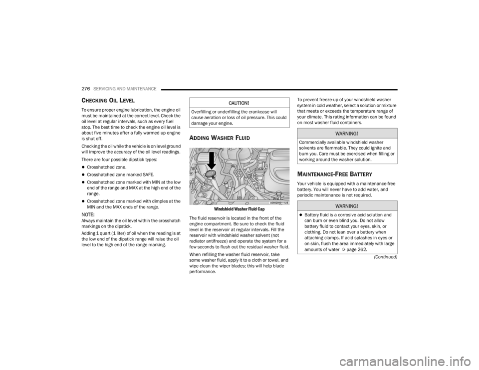
ADDING WASHER FLUID
Windshield Washer Fluid Cap
The fluid reservoir is located in the front of the
engine compartment. Be sure to check the fluid
level in the reservoir at regular intervals. Fill the
reservoir with windshield washer solvent (not
radiator antifreeze) and operate the system for a
few seconds to flush out the residual washer fluid.
When refilling the washer fluid reservoir, take
some washer fluid, apply it to a cloth or towel, and
wipe clean the wiper blades; this will help blade
performance. To prevent freeze-up of your windshield washer
system in cold weather, select a solution or mixture
that meets or exceeds the temperature range of
your climate. This rating information can be found
on most washer fluid containers.
MAINTENANCE-FREE BATTERY
Your vehicle is equipped with a maintenance-free
battery. You will never have to add water, and
periodic maintenance is not required.
CAUTION!
Overfilling or underfilling the crankcase will
cause aeration or loss of oil pressure. This could
damage your engine.
WARNING!
Commercially available windshield washer
solvents are flammable. They could ignite and
burn you. Care must be exercised when filling or
working around the washer solution.
WARNING!
Battery fluid is a corrosive acid solution and
can burn or even blind you. Do not allow
battery fluid to contact your eyes, skin, or
clothing. Do not lean over a battery when
attaching clamps. If acid splashes in eyes or
on skin, flush the area immediately with large
amounts of water
Úpage 262.
21_RUV_OM_EN_USC_t.book Page 276
Page 291 of 348
SERVICING AND MAINTENANCE289
(Continued)
Make sure that the coolant expansion bottle
overflow hoses are not kinked or obstructed.
Keep the front of the radiator clean. If your
vehicle is equipped with air conditioning, keep
the front of the condenser clean.
Do not change the thermostat for Summer or
Winter operation. If replacement is ever neces -
sary, install ONLY the correct type thermostat.
Other designs may result in unsatisfactory
engine cooling performance, poor gas mileage,
and increased emissions.
BRAKE SYSTEM
In order to ensure brake system performance, all
brake system components should be inspected
periodically. For the proper maintenance intervals
Úpage 272.
Brake Master Cylinder
The fluid in the master cylinder should be checked
when performing under hood services or
immediately if the “Brake Warning Light” is
illuminated.
Be sure to clean the top of the master cylinder area
before removing the cap. If necessary, add fluid to
bring the fluid level up to the requirements
described on the brake fluid reservoir. With disc
brakes, fluid level can be expected to fall as the
brake pads wear. Brake fluid level should be
checked when pads are replaced. However, low
fluid level may be caused by a leak and a checkup
may be needed.
Use only manufacturer recommended brake fluid
Úpage 327.
WARNING!
Riding the brakes can lead to brake failure and
possibly a collision. Driving with your foot resting
or riding on the brake pedal can result in
abnormally high brake temperatures, excessive
lining wear, and possible brake damage. You
would not have your full braking capacity in an
emergency.
WARNING!
Use only manufacturer recommended brake
fluid Úpage 327. Using the wrong type of
brake fluid can severely damage your brake
system and/or impair its performance. The
proper type of brake fluid for your vehicle is
also identified on the original factory installed
hydraulic master cylinder reservoir.
To avoid contamination from foreign matter or
moisture, use only new brake fluid or fluid that
has been in a tightly closed container. Keep
the master cylinder reservoir cap secured at
all times. Brake fluid in a open container
absorbs moisture from the air resulting in a
lower boiling point. This may cause it to boil
unexpectedly during hard or prolonged
braking, resulting in sudden brake failure. This
could result in a collision.
Overfilling the brake fluid reservoir can result
in spilling brake fluid on hot engine parts,
causing the brake fluid to catch fire. Brake
fluid can also damage painted and vinyl
surfaces, care should be taken to avoid its
contact with these surfaces.
Do not allow petroleum-based fluid to contam -
inate the brake fluid. Brake seal components
could be damaged, causing partial or
complete brake failure. This could result in a
collision.
WARNING!
8
21_RUV_OM_EN_USC_t.book Page 289
Page 341 of 348

339
Spare Tire Changing
...................................... 249Spare Tire Stowage....................................... 256Spare Tires........................ 250, 313, 314, 315Specifications Oil.............................................................. 326Speed ControlCancel....................................................... 122Resume..................................................... 122Starting................................................... 16, 106Button......................................................... 15Cold Weather............................................ 109Engine Fails To Start................................. 109Remote....................................................... 16Starting And Operating.................................. 106Starting Procedures....................................... 106Steering......................................................... 118Tilt Column.................................................. 27Wheel, Heated............................................. 27Wheel, Tilt................................................... 27Steering Wheel Audio Controls...................... 159Steering Wheel Mounted Sound System.......159Store Radio Presets....................................... 166Stow ‘n Go (Fold In Floor) Seats....................... 37Stuck, Freeing............................................... 267Sunglasses Storage......................................... 71Supplemental Restraint System – Air Bag..... 214Sway Control, Trailer...................................... 191Symbol Glossary................................................ 8Synthetic Engine Oil....................................... 278System, Remote Starting................................. 16
T
Telescoping Steering Column.......................... 27Temperature Control, Automatic (ATC)............. 69Tie Down Hooks, Cargo.................................... 82Tilt Steering Column........................................ 27Time DelayHeadlight..................................................... 53Tire And Loading Information Placard........... 306Tire Markings................................................ 302Tire Safety Information................................. 301Tire Service Kit.............................................. 257Tire Stowage................................................. 256Tires......................... 243, 309, 313, 314, 318Aging (Life Of Tires).................................. 312Air Pressure.............................................. 309Chains...................................................... 316Changing.................................................. 249Compact Spare......................................... 314General Information............... 309, 313, 314High Speed............................................... 310Inflation Pressure..................................... 310Jacking............................................ 249, 251Life Of Tires.............................................. 312Load Capacity........................................... 306Pressure Monitoring System(TPMS)................................. 91, 101, 199Quality Grading......................................... 318Radial....................................................... 310Replacement............................................ 312Rotation.................................................... 317
Safety.............................................. 301, 309Sizes......................................................... 303Snow Tires................................................ 313Spare Tires................... 250, 313, 314, 315Spinning................................................... 311Trailer Towing........................................... 136Tread Wear Indicators.............................. 311Wheel Nut Torque..................................... 322To Open Hood..................................................80Tongue Weight/Trailer Weight...................... 134Towing........................................................... 130Disabled Vehicle....................................... 268Guide........................................................ 132Recreational............................................. 138Weight...................................................... 132Towing Behind A Motorhome........................ 138Traction......................................................... 139Traction Control............................................ 191Trailer Sway Control (TSC)............................. 191Trailer Towing................................................ 130Hitches..................................................... 132Minimum Requirements........................... 135Tips........................................................... 137Trailer And Tongue Weight........................ 134Wiring....................................................... 136Trailer Towing Guide..................................... 132Trailer Weight................................................ 132TransaxleAutomatic................................................. 113Operation.................................................. 113
11
21_RUV_OM_EN_USC_t.book Page 339