four wheel drive CHRYSLER VOYAGER 2021 Owners Manual
[x] Cancel search | Manufacturer: CHRYSLER, Model Year: 2021, Model line: VOYAGER, Model: CHRYSLER VOYAGER 2021Pages: 348, PDF Size: 18.73 MB
Page 120 of 348
118STARTING AND OPERATING
In the event of a momentary problem, the
transmission can be reset to regain all forward
gears by performing the following steps:
1. Stop the vehicle.
2. Shift the transmission into PARK, if possible. If not, shift the transmission to NEUTRAL.
3. Push and hold the ignition switch until the engine turns off.
4. Wait approximately 30 seconds.
5. Restart the engine.
6. Shift into the desired gear range. If the problem is no longer detected, the
transmission will return to normal operation.
NOTE:Even if the transmission can be reset, we
recommend that you visit an authorized dealer at
your earliest possible convenience. An authorized
dealer has diagnostic equipment to assess the
condition of your transmission. If the transmission
cannot be reset, authorized dealer service is
required.
Torque Converter Clutch
A feature designed to improve fuel economy has
been included in the automatic transmission on
your vehicle. A clutch within the torque converter
engages automatically at calibrated speeds. This
may result in a slightly different feeling or response during normal operation in the upper gears. When
the vehicle speed drops or during some
accelerations, the clutch automatically
disengages.
NOTE:The torque converter clutch will not engage until
the engine and/or transmission is warm (usually
after 1 to 3 miles [2 to 5 km] of driving). Because
the engine speed is higher when the torque
converter clutch is not engaged, it may seem as if
the transmission is not shifting properly when the
vehicle is cold. This is normal. The torque converter
clutch will function normally once the powertrain is
sufficiently warm.
ACTIVE NOISE CANCELLATION
Your vehicle is equipped with an Active Noise
Cancellation System. This system is designed to
address exhaust and engine noise. The system
relies on four microphones embedded in the
headliner, which monitor exhaust and engine
noise, and assists an onboard frequency
generator, which creates counteracting sound
waves in the audio system’s speakers. This helps
keep the vehicle quiet at idle and during drive.
POWER STEERING
The electric power steering system will provide
increased vehicle response and ease of
maneuverability. The power steering system
adapts to different driving conditions.
If the Steering icon is displayed and the “POWER
STEERING SYSTEM OVER TEMP” message is
displayed on the instrument cluster screen, this
indicates an over temperature condition in the
power steering system. Once driving conditions are
safe, pull over and let the vehicle idle for a few
moments until the icon and message turn off
Úpage 97.
If the “SERVICE POWER STEERING" OR
"POWER STEERING ASSIST OFF -
SERVICE SYSTEM” message and a
steering wheel icon are displayed on the
instrument cluster screen, it indicates that the
vehicle needs to be taken to the dealer for service.
It is likely the vehicle has lost power steering
assistance
Úpage 97.
WARNING!
Continued operation with reduced assist could
pose a safety risk to yourself and others. Service
should be obtained as soon as possible.
21_RUV_OM_EN_USC_t.book Page 118
Page 137 of 348

STARTING AND OPERATING135
Towing Requirements — Tires
Do not attempt to tow a trailer while using a
compact spare tire.
Do not drive more than 50 mph (80 km/h) when
towing while using a full size spare tire.
Proper tire inflation pressures are essential to
the safe and satisfactory operation of your
vehicle.
Check the trailer tires for proper tire inflation
pressures before trailer usage.
Check for signs of tire wear or visible tire
damage before towing a trailer.
Replacing tires with a higher load carrying
capacity will not increase the vehicle's GVWR
and GAWR limits.
For further information Úpage 309.
Towing Requirements — Trailer Brakes
Do not interconnect the hydraulic brake system
or vacuum system of your vehicle with that of
the trailer. This could cause inadequate braking
and possible personal injury.
An electronically actuated trailer brake
controller is required when towing a trailer with
electronically actuated brakes. When towing a
trailer equipped with a hydraulic surge actuated
brake system, an electronic brake controller is
not required.
Trailer brakes are recommended for trailers
over 1,000 lb (453 kg) and required for trailers
in excess of 2,000 lb (907 kg).
Vehicles with trailers should not be parked on
a grade. When parking, apply the parking
brake on the tow vehicle. Put the tow vehicle
transmission in PARK. For four-wheel drive
vehicles, make sure the transfer case is not in
NEUTRAL. Always, block or "chock" the trailer
wheels.
GCWR must not be exceeded.
Total weight must be distributed between the
tow vehicle and the trailer such that the
following four ratings are not exceeded :
GVWR
GTW
GAWR
Tongue weight rating for the trailer hitch
utilized.
WARNING!
4
21_RUV_OM_EN_USC_t.book Page 135
Page 141 of 348
STARTING AND OPERATING139
Recreational Towing
Front-Wheel Drive (FWD) Models
Recreational towing is allowed ONLY if the front
wheels are OFF the ground. This may be
accomplished using a tow dolly (front wheels off
the ground) or vehicle trailer (all four wheels off the
ground). If using a tow dolly, follow this procedure:
1. Properly secure the dolly to the tow vehicle, following the dolly manufacturer's
instructions.
2. Drive the front wheels onto the tow dolly.
3. Apply the parking brake.
4. Place the transmission in PARK.
5. Turn the ignition OFF.
6. Properly secure the front wheels to the dolly, following the dolly manufacturer's instructions.
7. Turn the ignition to the ON/RUN mode, but do not start the vehicle.
8. Press and hold the brake pedal.
9. Release the parking brake.
10. Turn the ignition OFF.
11. Release the brake pedal.
DRIVING TIPS
DRIVING ON SLIPPERY SURFACES
Information in this section will aid in safe
controlled launches in adverse conditions.
Acceleration
Rapid acceleration on snow covered, wet, or other
slippery surfaces may cause the driving wheels to
pull erratically to the right or left. This phenomenon
occurs when there is a difference in the surface
traction under the front (driving) wheels.
Traction
When driving on wet or slushy roads, it is possible
for a wedge of water to build-up between the tire
and road surface. This is hydroplaning and may
cause partial or complete loss of vehicle control
and stopping ability. To reduce this possibility, the
following precautions should be observed:
Slow down during rainstorms or when the roads
are slushy.
Slow down if the road has standing water or
puddles.
Replace the tires when tread wear indicators
first become visible.
Keep tires properly inflated.
Maintain sufficient distance between your
vehicle and the vehicle in front of you to avoid a
collision in a sudden stop.
WARNING!
Rapid acceleration on slippery surfaces is
dangerous. Unequal traction can cause sudden
pulling of the front wheels. You could lose
control of the vehicle and possibly have a
collision. Accelerate slowly and carefully
whenever there is likely to be poor traction (ice,
snow, wet, mud, loose sand, etc.).
4
21_RUV_OM_EN_USC_t.book Page 139
Page 188 of 348
186 (Continued)
SAFETY
SAFETY FEATURES
ANTI-LOCK BRAKE SYSTEM (ABS)
The ABS provides increased vehicle stability and
brake performance under most braking conditions.
The system automatically prevents wheel lock and
enhances vehicle control during braking.
The ABS performs a self-check cycle to ensure that
the ABS is working properly each time the vehicle
is started and driven. During this self-check, you
may hear a slight clicking sound as well as some
related motor noises.
The ABS is activated during braking when the
system detects one or more wheels are beginning
to lock. Road conditions such as ice, snow, gravel,
bumps, railroad tracks, loose debris, or panic stops
may increase the likelihood of ABS activation(s).
You also may experience the following normal
characteristics when the ABS activates:
ABS motor noise or clicking sounds (you may
continue to hear for a short time after the stop)
Brake pedal pulsations
A slight drop of the brake pedal at the end of the
stopThe ABS is designed to function with the Original
Equipment Manufacturer (OEM) tires. Modification
may result in degraded ABS performance.
Anti-Lock Brake System (ABS) Warning
Light
The yellow ABS Warning Light will turn on when the
ignition is placed in the ON/RUN mode and may
stay on for as long as four seconds.
If the ABS Warning Light remains on or comes on
while driving, it indicates that the anti-lock portion
of the brake system is not functioning and that
service is required. However, the conventional
brake system will continue to operate normally if
the ABS Warning Light is on.
WARNING!
The ABS contains sophisticated electronic
equipment that may be susceptible to interfer
-
ence caused by improperly installed or high
output radio transmitting equipment. This
interference can cause possible loss of
anti-lock braking capability. Installation of
such equipment should be performed by qual -
ified professionals.
Pumping of the Anti-Lock Brakes will diminish
their effectiveness and may lead to a collision.
Pumping makes the stopping distance longer.
Just press firmly on your brake pedal when you
need to slow down or stop.
The ABS cannot prevent the natural laws of
physics from acting on the vehicle, nor can it
increase braking or steering efficiency beyond
that afforded by the condition of the vehicle
brakes and tires or the traction afforded.
The ABS cannot prevent collisions, including
those resulting from excessive speed in turns,
following another vehicle too closely, or hydro -
planing.
The capabilities of an ABS equipped vehicle
must never be exploited in a reckless or
dangerous manner that could jeopardize the
user’s safety or the safety of others.
WARNING!
21_RUV_OM_EN_USC_t.book Page 186
Page 189 of 348
SAFETY187
If the ABS Warning Light is on, the brake system
should be serviced as soon as possible to restore
the benefits of Anti-Lock Brakes. If the ABS
Warning Light does not come on when the ignition
is placed in the ON/RUN mode, have the light
repaired as soon as possible.
ELECTRONIC BRAKE CONTROL (EBC)
S
YSTEM
Your vehicle is equipped with an advanced
Electronic Brake Control (EBC) system. This system
includes Anti-Lock Brake System (ABS), Brake
Assist System (BAS), Electronic Brake Force
Distribution (EBD), Electronic Roll Mitigation
(ERM), Electronic Stability Control (ESC), Hill Start
Assist (HSA), and Traction Control System
(TCS).These systems work together to enhance
both vehicle stability and control in various driving
conditions.
Your vehicle may also be equipped with Dynamic
Steering Torque (DST), Ready Alert Braking (RAB),
Rain Brake Support (RBS) and Trailer Sway Control
(TSC).
Brake Assist System (BAS)
The BAS is designed to optimize the vehicle’s
braking capability during emergency braking
maneuvers. The system detects an emergency
braking situation by sensing the rate and amount
of brake application and then applies optimum
pressure to the brakes. This can help reduce
braking distances. The BAS complements the
Anti-Lock Brake System (ABS). Applying the brakes
very quickly results in the best BAS assistance. To
receive the benefit of the system, you must apply
continuous braking pressure during the stopping
sequence (do not “pump” the brakes). Do not
reduce brake pedal pressure unless braking is no
longer desired. Once the brake pedal is released,
the BAS is deactivated.
Brake System Warning Light
The red Brake System Warning Light will turn on
when the ignition is placed in the ON/RUN mode
and may stay on for as long as four seconds.
If the Brake System Warning Light remains on or
comes on while driving, it indicates that the brake
system is not functioning properly and that
immediate service is required. If the Brake System
Warning Light does not come on when the ignition
is placed in the ON/RUN mode, have the light
repaired as soon as possible.
Dynamic Steering Torque (DST)
DST is a feature of the ESC and Electric Power
Steering (EPS) modules that provides torque at the
steering wheel for certain driving conditions in
which the ESC module is detecting vehicle
instability. The torque that the steering wheel
receives is only meant to help the driver realize
optimal steering behavior in order to reach/
maintain vehicle stability. The only notification the
driver receives that the feature is active, is the
torque applied to the steering wheel.
WARNING!
The Brake Assist System (BAS) cannot prevent
the natural laws of physics from acting on the
vehicle, nor can it increase the traction afforded
by prevailing road conditions. BAS cannot
prevent collisions, including those resulting from
excessive speed in turns, driving on very slippery
surfaces, or hydroplaning. The capabilities of a
BAS-equipped vehicle must never be exploited in
a reckless or dangerous manner, which could
jeopardize the user's safety or the safety of
others.
6
21_RUV_OM_EN_USC_t.book Page 187
Page 202 of 348

200SAFETY
NOTE:
The TPMS is not intended to replace normal tire
care and maintenance, or to provide warning of
a tire failure or condition.
The TPMS should not be used as a tire pressure
gauge while adjusting your tire pressure.
Driving on a significantly underinflated tire
causes the tire to overheat and can lead to tire
failure. Underinflation also reduces fuel effi -
ciency and tire tread life, and may affect the
vehicle’s handling and stopping ability.
The TPMS is not a substitute for proper tire
maintenance, and it is the driver’s responsibility
to maintain correct tire pressure using an accu -
rate tire pressure gauge, even if underinflation
has not reached the level to trigger illumination
of the TPMS Warning Light.
Seasonal temperature changes will affect tire
pressure, and the TPMS will monitor the actual
tire pressure in the tire.
Premium System
The Tire Pressure Monitoring System (TPMS) uses
wireless technology with wheel rim mounted
electronic sensors to monitor tire pressure levels.
Sensors, mounted to each wheel as part of the
valve stem, transmit tire pressure readings to the
receiver module.
NOTE:It is particularly important for you to check the tire
pressure in all of the tires on your vehicle monthly
and to maintain the proper pressure.
The TPMS consists of the following components:
Receiver module
Four Tire Pressure Monitoring System sensors
Various Tire Pressure Monitoring System
messages, which display in the instrument
cluster
Tire Pressure Monitoring System Warning Light
SERVICE TPMS WARNING
When a system fault is detected, the Tire Pressure
Monitoring System (TPMS) Warning Light will flash
on and off for 75 seconds and then remain on
solid. The system fault will also sound a chime. In
addition, the instrument cluster will display a
"SERVICE TPM SYSTEM" message for a minimum
of five seconds and then display dashes (--) in
place of the pressure value to indicate which
sensor is not being received.
CAUTION!
The TPMS has been optimized for the original
equipment tires and wheels. TPMS pressures
and warning have been established for the tire
size equipped on your vehicle. Undesirable
system operation or sensor damage may
result when using replacement equipment
that is not of the same size, type, and/or style.
The TPMS sensor is not designed for use on
aftermarket wheels and may contribute to a
poor overall system performance or sensor
damage. Customers are encouraged to use
OEM wheels to ensure proper TPMS feature
operation.
Using aftermarket tire sealants may cause the
Tire Pressure Monitoring System (TPMS)
sensor to become inoperable. After using an
aftermarket tire sealant it is recommended
that you take your vehicle to an authorized
dealer to have your sensor function checked.
After inspecting or adjusting the tire pressure
always reinstall the valve stem cap. This will
prevent moisture and dirt from entering the
valve stem, which could damage the TPMS
sensor.
21_RUV_OM_EN_USC_t.book Page 200
Page 203 of 348
SAFETY201
If the ignition is cycled, this sequence will repeat,
providing the system fault still exists. If the system
fault no longer exists, the TPMS Warning Light will
no longer flash, and the “SERVICE TPM SYSTEM”
message will no longer display, and a pressure
value will display in place of the dashes. A system
fault can occur due to any of the following:
Jamming due to electronic devices or driving
next to facilities emitting the same radio
frequencies as the TPMS sensors
Installing some form of aftermarket window
tinting that affects radio wave signals
Lots of snow or ice around the wheels or wheel
housings
Using tire chains on the vehicle
Using wheels/tires not equipped with TPMS
sensors
Vehicles With Compact Spare — If Equipped
1. The compact spare tire does not have a Tire Pressure Monitoring System sensor.
Therefore, the TPMS will not monitor the
pressure in the compact spare tire.
2. If you install the compact spare tire in place of
a road tire that has a pressure below the
low-pressure warning limit, the “Inflate to XX”
message will continue to be displayed. Upon
the next ignition cycle, the TPMS Warning Light
will remain on and a chime will sound. In
addition, the graphic in the instrument cluster
will still display a different color pressure
value.
3. After driving the vehicle for up to 20 minutes above 15 mph (24 km/h), the TPMS Warning
Light will flash on and off for 75 seconds and
then remain on solid. In addition, the
instrument cluster will display a “SERVICE TPM
SYSTEM” message for five seconds and then
display dashes (--) in place of the pressure
value.
4. For each subsequent ignition cycle, a chime will sound, the TPMS Warning Light will flash
on and off for 75 seconds and then remain on
solid, and the instrument cluster will display a
“SERVICE TPM SYSTEM” message for five
seconds and then display dashes (- -) in place
of the pressure value.
5. Once you repair or replace the original road tire and reinstall it on the vehicle in place of the
compact spare, the TPMS will update automat -
ically. In addition, the TPMS Warning Light will
turn off and the graphic in the instrument
cluster will display a new pressure value instead of dashes (--), as long as no tire
pressure is below the low-pressure warning
limit in any of the four active road tires. The
vehicle may need to be driven for up to
20 minutes above 15 mph (24 km/h) in order
for the TPMS to receive this information.
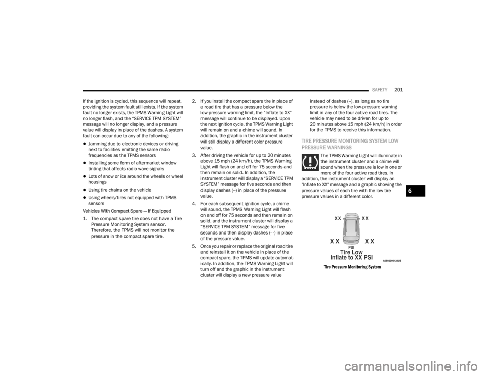
TIRE PRESSURE MONITORING SYSTEM LOW
PRESSURE WARNINGS
The TPMS Warning Light will illuminate in
the instrument cluster and a chime will
sound when tire pressure is low in one or
more of the four active road tires. In
addition, the instrument cluster will display an
"Inflate to XX" message and a graphic showing the
pressure values of each tire with the low tire
pressure values in a different color.
Tire Pressure Monitoring System
6
21_RUV_OM_EN_USC_t.book Page 201
Page 204 of 348

202SAFETY
Should this occur, you should stop as soon as
possible and inflate the tires with low pressure
(those in a different color in the instrument cluster
graphic) to the vehicle’s recommended cold
placard pressure value as shown in the "Inflate to
XX" message. Once the system receives the
updated tire pressures, the system will
automatically update, the pressure values in the
graphic display in the instrument cluster will return
to their original color, and the TPMS Warning Light
will turn off. The vehicle may need to be driven for
up to 20 minutes above 15 mph (24 km/h) in
order for the TPMS to receive this information.
TPMS DEACTIVATION — IF EQUIPPED
The Tire Pressure Monitoring System (TPMS) can
be deactivated if replacing all four wheel and tire
assemblies (road tires) with wheel and tire
assemblies that do not have TPMS sensors, such
as when installing winter wheel and tire
assemblies on your vehicle.
To deactivate the TPMS, first, replace all four wheel
and tire assemblies (road tires) with tires not
equipped with Tire Pressure Monitoring System
sensors. Then, drive the vehicle for 20 minutes
above 15 mph (24 km/h). The TPMS will chime,
the TPMS Warning Light will flash on and off for
75 seconds and then remain on. The instrument
cluster will display the “SERVICE TPM SYSTEM”
message and then display dashes (--) in place of
the pressure values. Beginning with the next ignition cycle, the TPMS
will no longer chime or display the “SERVICE TPM
SYSTEM” message in the instrument cluster but
dashes (--) will remain in place of the pressure
values.
To reactivate the TPMS, replace all four wheel and
tire assemblies (road tires) with tires equipped with
TPMS sensors. Then, drive the vehicle for up to
20 minutes above 15 mph (24 km/h). The TPMS
will chime, the TPMS Warning Light will flash on
and off for 75 seconds and then turn off. The
instrument cluster will display the “SERVICE TPM
SYSTEM” message and then display pressure
values in place of the dashes. On the next ignition
cycle the "SERVICE TPM SYSTEM" message will no
longer be displayed as long as no system fault
exists.
OCCUPANT RESTRAINT SYSTEMS
Some of the most important safety features in your
vehicle are the restraint systems:
OCCUPANT RESTRAINT SYSTEMS
F
EATURES
Seat Belt Systems
Supplemental Restraint Systems (SRS) Air Bags
Child Restraints Some of the safety features described in this
section may be standard equipment on some
models, or may be optional equipment on others.
If you are not sure, ask an authorized dealer.
IMPORTANT SAFETY PRECAUTIONS
Please pay close attention to the information in
this section. It tells you how to use your restraint
system properly, to keep you and your passengers
as safe as possible.
Here are some simple steps you can take to
minimize the risk of harm from a deploying air bag:
1. Children 12 years old and under should
always ride buckled up in the rear seat of a
vehicle with a rear seat.
2. A child who is not big enough to wear the vehicle seat belt properly must be secured in
the appropriate child restraint or
belt-positioning booster seat in a rear seating
position
Úpage 225.
3. If a child from 2 to 12 years old (not in a rear-facing child restraint) must ride in the
front passenger seat, move the seat as far
back as possible and use the proper child
restraint
Úpage 225.
4. Never allow children to slide the shoulder belt behind them or under their arm.
21_RUV_OM_EN_USC_t.book Page 202