service reset CHRYSLER VOYAGER 2021 Owners Manual
[x] Cancel search | Manufacturer: CHRYSLER, Model Year: 2021, Model line: VOYAGER, Model: CHRYSLER VOYAGER 2021Pages: 348, PDF Size: 18.73 MB
Page 93 of 348
GETTING TO KNOW YOUR INSTRUMENT PANEL91
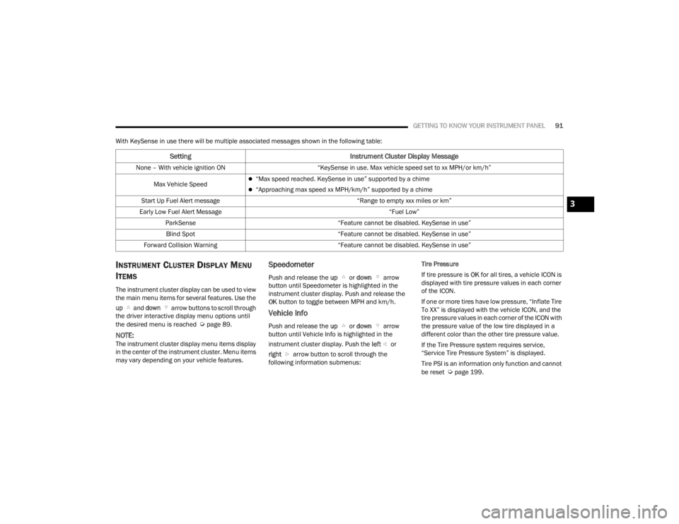
With KeySense in use there will be multiple associated messages shown in the following table:
INSTRUMENT CLUSTER DISPLAY MENU
I
TEMS
The instrument cluster display can be used to view
the main menu items for several features. Use the
up and down arrow buttons to scroll through
the driver interactive display menu options until
the desired menu is reached
Úpage 89.
NOTE:The instrument cluster display menu items display
in the center of the instrument cluster. Menu items
may vary depending on your vehicle features.
Speedometer
Push and release the up or down arrow
button until Speedometer is highlighted in the
instrument cluster display. Push and release the
OK button to toggle between MPH and km/h.
Vehicle Info
Push and release the up or down arrow
button until Vehicle Info is highlighted in the
instrument cluster display. Push the left or
right arrow button to scroll through the
following information submenus: Tire Pressure
If tire pressure is
OK for all tires, a vehicle ICON is
displayed with tire pressure values in each corner
of the ICON.
If one or more tires have low pressure, “Inflate Tire
To XX” is displayed with the vehicle ICON, and the
tire pressure values in each corner of the ICON with
the pressure value of the low tire displayed in a
different color than the other tire pressure value.
If the Tire Pressure system requires service,
“Service Tire Pressure System” is displayed.
Tire PSI is an information only function and cannot
be reset
Úpage 199.
Setting Instrument Cluster Display Message
None – With vehicle ignition ON “KeySense in use. Max vehicle speed set to xx MPH/or km/h”
Max Vehicle Speed
“Max speed reached. KeySense in use” supported by a chime
“Approaching max speed xx MPH/km/h” supported by a chime
Start Up Fuel Alert message “Range to empty xxx miles or km”
Early Low Fuel Alert Message “Fuel Low”
ParkSense “Feature cannot be disabled. KeySense in use”
Blind Spot “Feature cannot be disabled. KeySense in use”
Forward Collision Warning “Feature cannot be disabled. KeySense in use”
3
21_RUV_OM_EN_USC_t.book Page 91
Page 98 of 348
96GETTING TO KNOW YOUR INSTRUMENT PANEL
Loss of the battery charge may indicate one or
more of the following conditions:
The charging system cannot deliver enough
electrical power to the vehicle system because
the electrical loads are larger than the capability
of charging system. The charging system is still
functioning properly.
Turning on all possible vehicle electrical loads
(e.g. HVAC to max settings, exterior and interior
lights, overloaded power outlets +12 Volts,
150W, USB ports) during certain driving condi -
tions (city driving, towing, frequent stopping).
Installing options like additional lights, upfitter
electrical accessories, audio systems, alarms
and similar devices.
Unusual driving cycles (short trips separated by
long parking periods).
The vehicle was parked for an extended period
of time (weeks, months).
The battery was recently replaced and was not
charged completely.
The battery was discharged by an electrical load
left on when the vehicle was parked.
The battery was used for an extended period
with the engine not running to supply radio,
lights, chargers, +12 Volt portable appliances
like vacuum cleaners, game consoles and
similar devices. What to do when an electrical load reduction
action message is present (“Battery Saver On” or
“Battery Saver Mode”)
During a trip:
Reduce power to unnecessary loads if possible:
Turn off redundant lights
(interior or exterior)
Check what may be plugged in to power
outlets +12 Volts, 150W, USB ports
Check HVAC settings (blower, temperature)
Check the audio settings (volume)
After a trip:
Check if any aftermarket equipment was
installed (additional lights, upfitter electrical
accessories, audio systems, alarms) and review
specifications if any (load and Ignition Off Draw
currents).
Evaluate the latest driving cycles (distance,
driving time and parking time).
The vehicle should have service performed if
the message is still present during consecutive
trips and the evaluation of the vehicle and
driving pattern did not help to identify the cause.
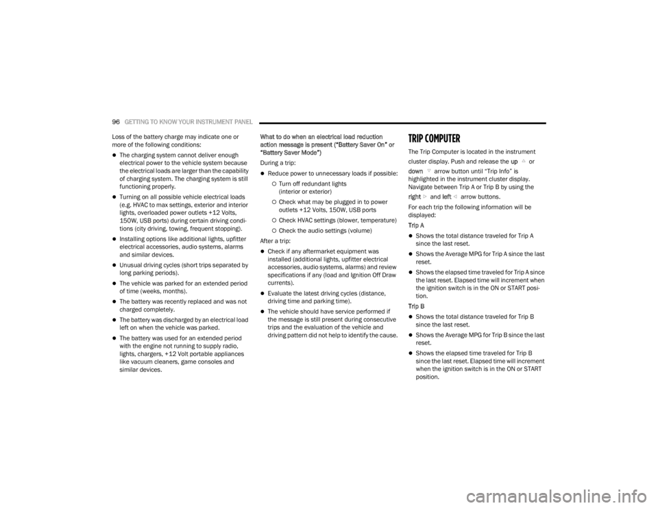
TRIP COMPUTER
The Trip Computer is located in the instrument
cluster display. Push and release the up or
down arrow button until “Trip Info” is
highlighted in the instrument cluster display.
Navigate between Trip A or Trip B by using the
right and left arrow buttons.
For each trip the following information will be
displayed:
Trip A
Shows the total distance traveled for Trip A
since the last reset.
Shows the Average MPG for Trip A since the last
reset.
Shows the elapsed time traveled for Trip A since
the last reset. Elapsed time will increment when
the ignition switch is in the ON or START posi -
tion.
Trip B
Shows the total distance traveled for Trip B
since the last reset.
Shows the Average MPG for Trip B since the last
reset.
Shows the elapsed time traveled for Trip B
since the last reset. Elapsed time will increment
when the ignition switch is in the ON or START
position.
21_RUV_OM_EN_USC_t.book Page 96
Page 99 of 348
GETTING TO KNOW YOUR INSTRUMENT PANEL97
To Reset A Trip Function
Push and hold the OK button to reset the currently
displayed trip.
WARNING LIGHTS AND MESSAGES
The warning/indicator lights will illuminate in the
instrument panel together with a dedicated
message and/or acoustic signal when applicable.
These indications are indicative and precautionary
and as such must not be considered as exhaustive
and/or alternative to the information contained in
the Owner’s Manual, which you are advised to read
carefully in all cases. Always refer to the
information in this chapter in the event of a failure
indication. All active telltales will display first if
applicable. The system check menu may appear
different based upon equipment options and
current vehicle status. Some telltales are optional
and may not appear.
RED WARNING LIGHTS
Air Bag Warning Light
This warning light will illuminate to
indicate a fault with the air bag, and will
turn on for four to eight seconds as a bulb
check when the ignition is placed in the
ON/RUN or ACC/ON/RUN position. This light will
illuminate with a single chime when a fault with the
air bag has been detected, it will stay on until the fault is cleared. If the light is either not on during
startup, stays on, or turns on while driving, have
the system inspected at an authorized dealer as
soon as possible.
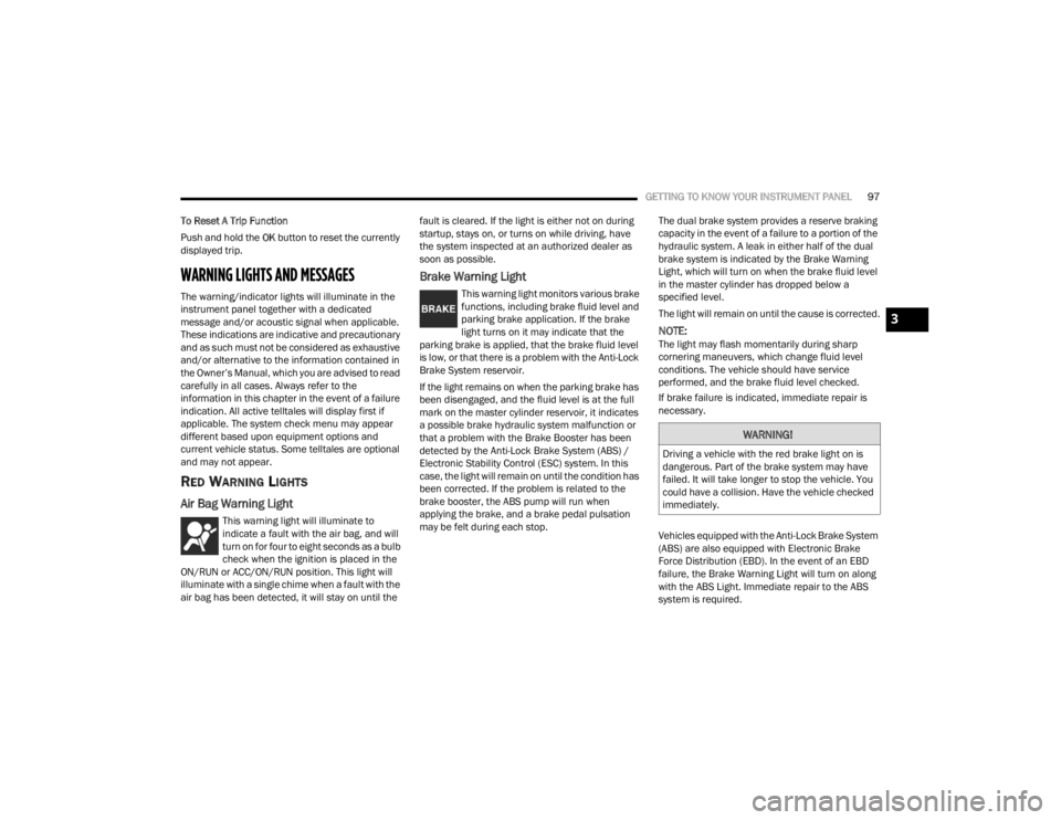
Brake Warning Light
This warning light monitors various brake
functions, including brake fluid level and
parking brake application. If the brake
light turns on it may indicate that the
parking brake is applied, that the brake fluid level
is low, or that there is a problem with the Anti-Lock
Brake System reservoir.
If the light remains on when the parking brake has
been disengaged, and the fluid level is at the full
mark on the master cylinder reservoir, it indicates
a possible brake hydraulic system malfunction or
that a problem with the Brake Booster has been
detected by the Anti-Lock Brake System (ABS) /
Electronic Stability Control (ESC) system. In this
case, the light will remain on until the condition has
been corrected. If the problem is related to the
brake booster, the ABS pump will run when
applying the brake, and a brake pedal pulsation
may be felt during each stop. The dual brake system provides a reserve braking
capacity in the event of a failure to a portion of the
hydraulic system. A leak in either half of the dual
brake system is indicated by the Brake Warning
Light, which will turn on when the brake fluid level
in the master cylinder has dropped below a
specified level.
The light will remain on until the cause is corrected.
NOTE:The light may flash momentarily during sharp
cornering maneuvers, which change fluid level
conditions. The vehicle should have service
performed, and the brake fluid level checked.
If brake failure is indicated, immediate repair is
necessary.
Vehicles equipped with the Anti-Lock Brake System
(ABS) are also equipped with Electronic Brake
Force Distribution (EBD). In the event of an EBD
failure, the Brake Warning Light will turn on along
with the ABS Light. Immediate repair to the ABS
system is required.
WARNING!
Driving a vehicle with the red brake light on is
dangerous. Part of the brake system may have
failed. It will take longer to stop the vehicle. You
could have a collision. Have the vehicle checked
immediately.
3
21_RUV_OM_EN_USC_t.book Page 97
Page 115 of 348
STARTING AND OPERATING113
(Continued)
Auto Park Brake
The Electric Park Brake (EPB) can be programmed
to be applied automatically whenever the vehicle is
at a standstill and the automatic transmission is
placed in PARK. Auto Park Brake is enabled and
disabled by customer selection through the
customer programmable features
Úpage 142.
SafeHold
SafeHold is a safety feature of the Electric Park
Brake (EPB) system that will engage the parking
brake automatically if the vehicle is left unsecured.
If the automatic transmission is not in PARK, the
seat belt is unbuckled, the driver door is open, the
vehicle is at a standstill, and there is no attempt to
press the brake pedal or accelerator pedal, the
parking brake will automatically engage to prevent
the vehicle from rolling.
SafeHold can be temporarily bypassed by pushing
the EPB while the driver door is open and brake
pedal is pressed. Once manually bypassed,
SafeHold will be enabled again once the vehicle
reaches 12 mph (20 km/h) or the ignition is cycled
to the OFF position and back to ON again.
Brake Service Mode
We recommend having your brakes serviced by an
authorized dealer. You should only make repairs
for which you have the knowledge and the right
equipment. You should only enter Brake Service
Mode during brake service. When servicing your rear brakes, it may be
necessary for you or your technician to push the
rear piston into the rear caliper bore. With the
Electric Park Brake (EPB) system, this can only be
done after retracting the EPB actuator.
Fortunately, actuator retraction can be done easily
by entering the brake service in your vehicle
Úpage 142. This menu based system will guide
you through the steps necessary to retract the EPB
actuator in order to perform rear brake service.
Brake Service Mode has requirements that must
be met in order to be activated:
The vehicle must be at a standstill.
The parking brake must be unapplied.
The transmission must be in PARK or NEUTRAL.
While in service mode, the EPB fault lamp will flash
continuously while the ignition switch is ON.
When brake service work is complete, the following
steps must be followed to reset the parking brake
system to normal operation:
Ensure the vehicle is at a standstill.
Press the brake pedal with moderate force.
Apply the EPB.
AUTOMATIC TRANSMISSION
You must press and hold the brake pedal while
shifting out of PARK.
WARNING!
You can be badly injured working on or around a
motor vehicle. Do only that service work for
which you have the knowledge and the right
equipment. If you have any doubt about your
ability to perform a service job, take your vehicle
to a competent mechanic.
WARNING!
Never use the PARK position as a substitute
for the parking brake. Always apply the
parking brake fully when exiting the vehicle to
guard against vehicle movement and possible
injury or damage.
Your vehicle could move and injure you and
others if it is not in PARK. Check by trying to
move the transmission gear selector out of
PARK with the brake pedal released. Make
sure the transmission is in PARK before
exiting the vehicle.
4
21_RUV_OM_EN_USC_t.book Page 113
Page 120 of 348
118STARTING AND OPERATING
In the event of a momentary problem, the
transmission can be reset to regain all forward
gears by performing the following steps:
1. Stop the vehicle.
2. Shift the transmission into PARK, if possible. If not, shift the transmission to NEUTRAL.
3. Push and hold the ignition switch until the engine turns off.
4. Wait approximately 30 seconds.
5. Restart the engine.
6. Shift into the desired gear range. If the problem is no longer detected, the
transmission will return to normal operation.
NOTE:Even if the transmission can be reset, we
recommend that you visit an authorized dealer at
your earliest possible convenience. An authorized
dealer has diagnostic equipment to assess the
condition of your transmission. If the transmission
cannot be reset, authorized dealer service is
required.
Torque Converter Clutch
A feature designed to improve fuel economy has
been included in the automatic transmission on
your vehicle. A clutch within the torque converter
engages automatically at calibrated speeds. This
may result in a slightly different feeling or response during normal operation in the upper gears. When
the vehicle speed drops or during some
accelerations, the clutch automatically
disengages.
NOTE:The torque converter clutch will not engage until
the engine and/or transmission is warm (usually
after 1 to 3 miles [2 to 5 km] of driving). Because
the engine speed is higher when the torque
converter clutch is not engaged, it may seem as if
the transmission is not shifting properly when the
vehicle is cold. This is normal. The torque converter
clutch will function normally once the powertrain is
sufficiently warm.
ACTIVE NOISE CANCELLATION
Your vehicle is equipped with an Active Noise
Cancellation System. This system is designed to
address exhaust and engine noise. The system
relies on four microphones embedded in the
headliner, which monitor exhaust and engine
noise, and assists an onboard frequency
generator, which creates counteracting sound
waves in the audio system’s speakers. This helps
keep the vehicle quiet at idle and during drive.
POWER STEERING
The electric power steering system will provide
increased vehicle response and ease of
maneuverability. The power steering system
adapts to different driving conditions.
If the Steering icon is displayed and the “POWER
STEERING SYSTEM OVER TEMP” message is
displayed on the instrument cluster screen, this
indicates an over temperature condition in the
power steering system. Once driving conditions are
safe, pull over and let the vehicle idle for a few
moments until the icon and message turn off
Úpage 97.
If the “SERVICE POWER STEERING" OR
"POWER STEERING ASSIST OFF -
SERVICE SYSTEM” message and a
steering wheel icon are displayed on the
instrument cluster screen, it indicates that the
vehicle needs to be taken to the dealer for service.
It is likely the vehicle has lost power steering
assistance
Úpage 97.
WARNING!
Continued operation with reduced assist could
pose a safety risk to yourself and others. Service
should be obtained as soon as possible.
21_RUV_OM_EN_USC_t.book Page 118
Page 122 of 348
120STARTING AND OPERATING
TO START THE ENGINE WHILE IN AUTO
S
TOP/START
While in a forward gear, the engine will start when
the brake pedal is released or the throttle pedal is
pressed. The transmission will automatically
re-engage upon engine restart.
Conditions That Will Cause The Engine To Start
Automatically While In Auto Stop/Start:
The transmission selector is moved out of
DRIVE.
To maintain cabin temperature comfort.
HVAC is set to full defrost mode.
HVAC system temperature or fan speed is
manually adjusted.
Battery voltage drops too low. During this time a
message will display "Stop/Start Not Ready
Battery Charging".
Stop/Start OFF switch is pushed.
A Stop/Start system error occurs.
TO MANUALLY TURN OFF THE
S
TOP/START SYSTEM
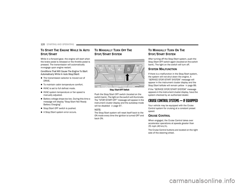
Stop/Start OFF Switch
Push the Stop/Start OFF switch (located on the
switch bank). The light on the switch will illuminate.
The “STOP/START OFF” message will appear in the
instrument cluster display and the autostop mode
will be disabled
Úpage 97.
NOTE:The Stop/Start system will reset itself back to the
ON mode every time the ignition is turned OFF and
back ON.
TO MANUALLY TURN ON THE
S
TOP/START SYSTEM
After turning off the Stop/Start system, push the
Stop/Start OFF switch again (located on the switch
bank). The light on the switch will turn off.
SYSTEM MALFUNCTION
If there is a malfunction in the Stop/Start system,
the system will not shut down the engine. A
“SERVICE STOP/START SYSTEM” message will
appear in the instrument cluster display and the
Stop/Start telltale will remain yellow
Úpage 89.
If the “SERVICE STOP/START SYSTEM” message
appears in the instrument cluster display, have the
system checked by an authorized dealer.
CRUISE CONTROL SYSTEMS — IF EQUIPPED
Your vehicle may be equipped with the Cruise
Control system for cruising at a constant preset
speed.
CRUISE CONTROL
When engaged, the Cruise Control takes over
accelerator operations at speeds greater than
25 mph (40 km/h).
The Cruise Control buttons are located on the right
side of the steering wheel.
21_RUV_OM_EN_USC_t.book Page 120
Page 164 of 348
162MULTIMEDIA
No Subscription
Radios equipped with a Satellite receiver require a
subscription to the SiriusXM® Service. When the
radio does not have the necessary subscription,
the radio is able to receive the Preview channel
only.
Acquiring SiriusXM® Subscription
To activate the SiriusXM® Satellite Radio
subscription, US residents visit
siriusxm.com/
getallaccess or call: 1-800-643-2112
Canadian residents visit
https://
www.siriusxm.ca/ or call: 1-888-539-7474.
NOTE:You will need to provide the SiriusXM® ID (RID)
located at the bottom of the Channel 0 screen.
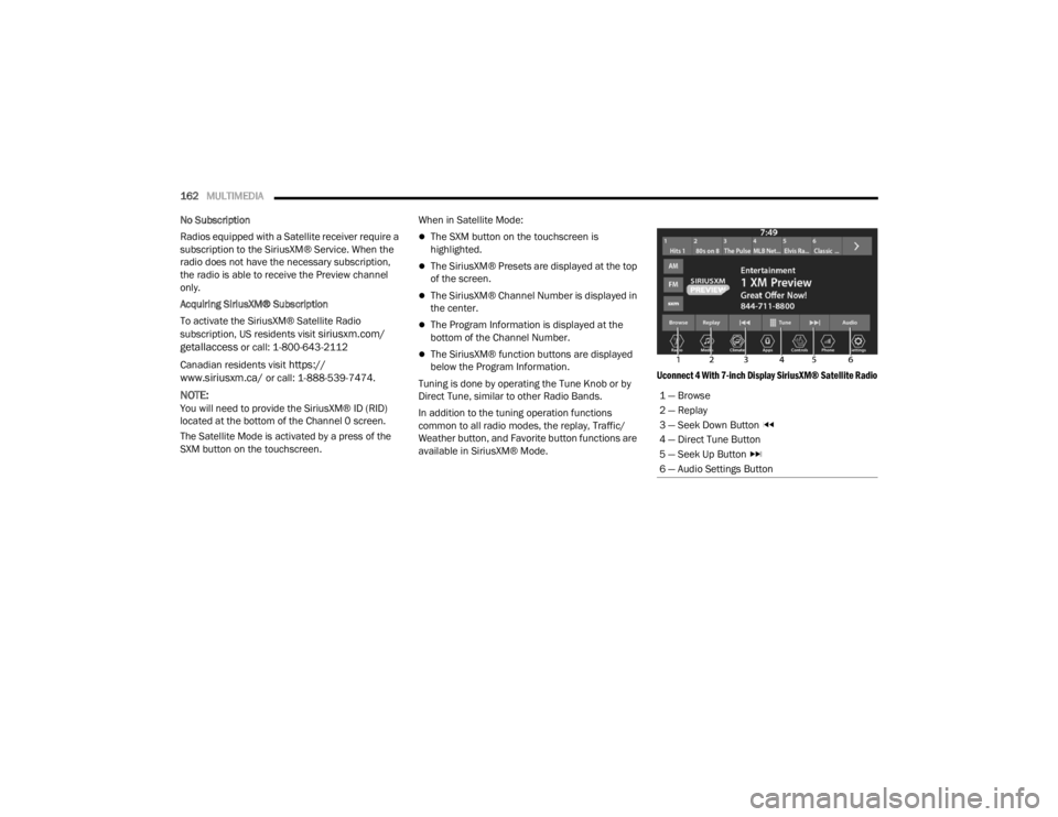
The Satellite Mode is activated by a press of the
SXM button on the touchscreen. When in Satellite Mode:
The SXM button on the touchscreen is
highlighted.
The SiriusXM® Presets are displayed at the top
of the screen.
The SiriusXM® Channel Number is displayed in
the center.
The Program Information is displayed at the
bottom of the Channel Number.
The SiriusXM® function buttons are displayed
below the Program Information.
Tuning is done by operating the Tune Knob or by
Direct Tune, similar to other Radio Bands.
In addition to the tuning operation functions
common to all radio modes, the replay, Traffic/
Weather button, and Favorite button functions are
available in SiriusXM® Mode.
Uconnect 4 With 7-inch Display SiriusXM® Satellite Radio
1 — Browse
2 — Replay
3 — Seek Down Button
4 — Direct Tune Button
5 — Seek Up Button
6 — Audio Settings Button
21_RUV_OM_EN_USC_t.book Page 162
Page 200 of 348
198SAFETY
FCW Limited Warning
If the instrument cluster displays “ACC/FCW
Limited Functionality” or “ACC/FCW Limited
Functionality Clean Front Windshield”
momentarily, there may be a condition that limits
FCW functionality. Although the vehicle is still
drivable under normal conditions, the active
braking may not be fully available. Once the
condition that limited the system performance is
no longer present, the system will return to its full
performance state. If the problem persists, see an
authorized dealer.
Service FCW Warning
If the system turns off, and the instrument cluster
displays:
ACC/FCW Unavailable Service Required
Cruise/FCW Unavailable Service Required
This indicates there is an internal system fault.
Although the vehicle is still drivable under normal
conditions, have the system checked by an
authorized dealer.
Pedestrian Emergency Braking (PEB) —
If Equipped
The Pedestrian Emergency Braking (PEB) is a
subsystem of the FCW system that provides the
driver with audible and visual warnings in the
instrument cluster display, and may apply
automatic braking when it detects a potential
frontal collision with a pedestrian.
If a PEB event begins at a speed below 37 mph
(60 km/h), the system may provide braking to
mitigate the potential collision with a pedestrian. If
the PEB event stops the vehicle completely, the
system will hold the vehicle at a standstill for two
seconds and then release the brakes. When the
system determines a collision with the pedestrian
in front of you is no longer probable, the warning
message will be deactivated.
The minimum speed for PEB activation is 3 mph
(5 km/h). Turning PEB On Or Off
NOTE:The default status of PEB is “On.” This allows the
system to warn you of a possible frontal collision
with the pedestrian.
The PEB button is located in the Uconnect display
in the Controls settings
Úpage 142.
To turn the PEB system off, push the Pedestrian
Emergency Braking button once.
To turn the PEB system back on, push the
Pedestrian Emergency Braking button again.
Changing the PEB status to “Off” deactivates the
system, so no warning or active braking will be
available in case of a possible frontal collision with
the pedestrian.
NOTE:The PEB system will NOT retain the last setting
selected by the driver after ignition shut down. The
system will reset to the default setting when the
vehicle is restarted.
WARNING!
Pedestrian Emergency Braking (PEB) is not
intended to avoid a collision on its own, nor can
PEB detect every type of potential collision with
a pedestrian. The driver has the responsibility to
avoid a collision by controlling the vehicle via
braking and steering. Failure to follow this
warning could lead to serious injury or death.
21_RUV_OM_EN_USC_t.book Page 198
Page 226 of 348
224SAFETY
(Continued)
Cut off battery power to the:
Engine
Electric Motor (if equipped)
Electric power steering
Brake booster
Electric park brake
Automatic transmission gear selector
Horn
Front wiper
Headlamp washer pump
NOTE:After an accident, remember to cycle the ignition to
the STOP (OFF/LOCK) position and remove the key
from the ignition switch to avoid draining the
battery. Carefully check the vehicle for fuel leaks in
the engine compartment and on the ground near
the engine compartment and fuel tank before
resetting the system and starting the engine. If
there are no fuel leaks or damage to the vehicle
electrical devices (e.g. headlights) after an
accident, reset the system by following the
procedure described below. If you have any doubt,
contact an authorized dealer.
Enhanced Accident Response System
Reset Procedure
In order to reset the Enhanced Accident Response
System functions after an event, the ignition switch
must be changed from ignition START or ON/RUN
to ignition OFF. Carefully check the vehicle for fuel
leaks in the engine compartment and on the
ground near the engine compartment and fuel
tank before resetting the system and starting the
engine.
After an accident, if the vehicle will not start after
performing the reset procedure, the vehicle must
be towed to an authorized dealer to be inspected
and to have the Enhanced Accident Response
System reset.
Maintaining Your Air Bag System Event Data Recorder (EDR)
This vehicle is equipped with an event data
recorder (EDR). The main purpose of an EDR is to
record, in certain crash or near crash-like
situations, such as an air bag deployment or hitting
a road obstacle, data that will assist in
understanding how a vehicle’s systems performed.
WARNING!
Modifications to any part of the air bag system
could cause it to fail when you need it. You
could be injured if the air bag system is not
there to protect you. Do not modify the compo-
nents or wiring, including adding any kind of
badges or stickers to the steering wheel hub
trim cover or the upper passenger side of the
instrument panel. Do not modify the front
fascia/bumper, vehicle body structure, or add
aftermarket side steps or running boards.
It is dangerous to try to repair any part of the
air bag system yourself. Be sure to tell anyone
who works on your vehicle that it has an air
bag system.
Do not attempt to modify any part of your air
bag system. The air bag may inflate acciden -
tally or may not function properly if modifica -
tions are made. Take your vehicle to an
authorized dealer for any air bag system
service. If your seat, including your trim cover
and cushion, needs to be serviced in any way
(including removal or loosening/tightening of
seat attachment bolts), take the vehicle to an
authorized dealer. Only manufacturer
approved seat accessories may be used. If it is
necessary to modify the air bag system for
persons with disabilities, contact an autho -
rized dealer.
WARNING!
21_RUV_OM_EN_USC_t.book Page 224
Page 273 of 348
271
SERVICING AND MAINTENANCE
SCHEDULED SERVICING
Your vehicle is equipped with an automatic oil
change indicator system. The oil change indicator
system will remind you that it is time to take your
vehicle in for scheduled maintenance.
Based on engine operation conditions, the oil
change indicator message will illuminate. This
means that service is required for your vehicle.
Operating conditions such as frequent short-trips,
trailer tow, extremely hot or cold ambient
temperatures will influence when the “Oil Change
Required” message is displayed. Have your vehicle
serviced as soon as possible, within the next
500 miles (805 km).An authorized dealer will reset the oil change
indicator message after completing the scheduled
oil change. If a scheduled oil change is performed
by someone other than an authorized dealer
Úpage 89.
NOTE:Under no circumstances should oil change
intervals exceed 10,000 miles (16,000 km),
12 months or 350 hours of engine run time,
whichever comes first. The 350 hours of engine
run or idle time is generally only a concern for fleet
customers.
Once A Month Or Before A Long Trip:
Check engine oil level
Check windshield washer fluid level
Check tire pressure and look for unusual wear
or damage. Rotate tires at the first sign of irreg
-
ular wear, even if it occurs before the oil indi -
cator system turns on
Check the fluid levels of the coolant reservoir
and brake master cylinder, fill as needed
Check function of all interior and exterior lights
8
21_RUV_OM_EN_USC_t.book Page 271