warning light CHRYSLER VOYAGER 2021 Owners Manual
[x] Cancel search | Manufacturer: CHRYSLER, Model Year: 2021, Model line: VOYAGER, Model: CHRYSLER VOYAGER 2021Pages: 348, PDF Size: 18.73 MB
Page 5 of 348
3
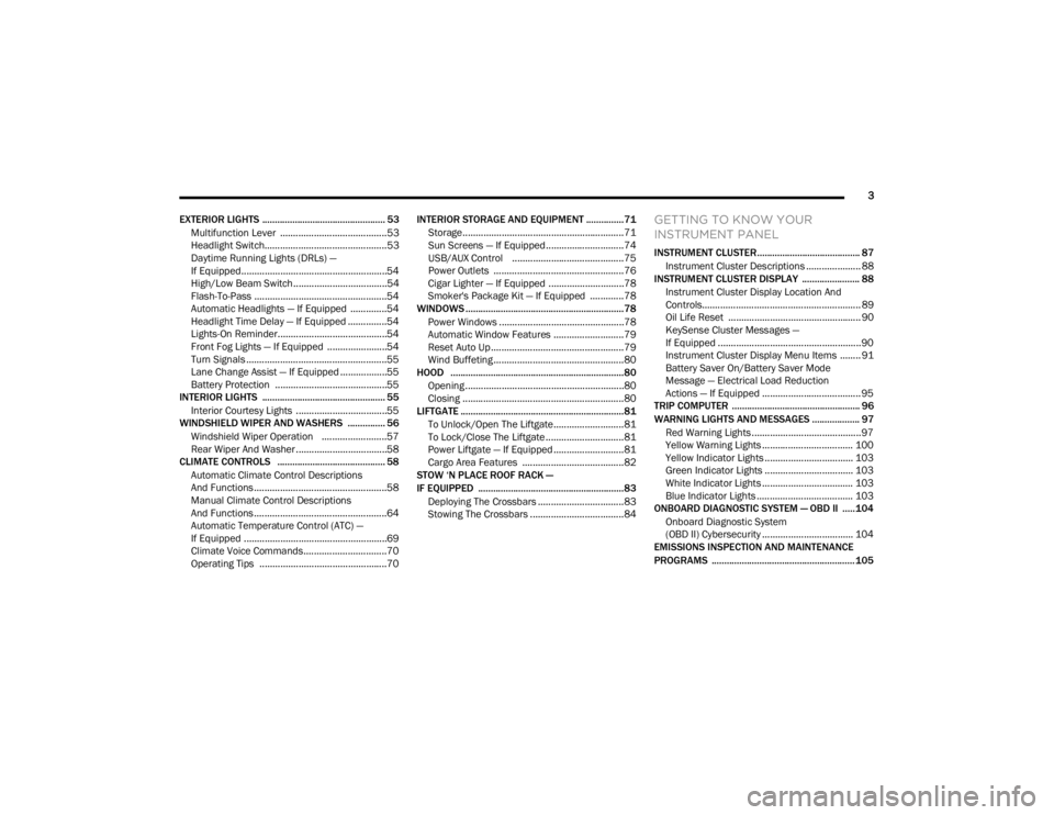
EXTERIOR LIGHTS ................................................. 53 Multifunction Lever .........................................53
Headlight Switch...............................................53
Daytime Running Lights (DRLs) —
If Equipped........................................................54
High/Low Beam Switch....................................54
Flash-To-Pass ...................................................54
Automatic Headlights — If Equipped ..............54
Headlight Time Delay — If Equipped ...............54
Lights-On Reminder..........................................54
Front Fog Lights — If Equipped .......................54
Turn Signals ......................................................55
Lane Change Assist — If Equipped ..................55
Battery Protection ...........................................55
INTERIOR LIGHTS ................................................. 55
Interior Courtesy Lights ...................................55
WINDSHIELD WIPER AND WASHERS ............... 56
Windshield Wiper Operation .........................57
Rear Wiper And Washer ...................................58
CLIMATE CONTROLS ........................................... 58
Automatic Climate Control Descriptions
And Functions ...................................................58
Manual Climate Control Descriptions
And Functions ...................................................64
Automatic Temperature Control (ATC) —
If Equipped .......................................................69
Climate Voice Commands................................70
Operating Tips .................................................70 INTERIOR STORAGE AND EQUIPMENT ............... 71
Storage..............................................................71
Sun Screens — If Equipped..............................74
USB/AUX Control ...........................................75
Power Outlets ..................................................76
Cigar Lighter — If Equipped .............................78
Smoker's Package Kit — If Equipped .............78
WINDOWS ...............................................................78
Power Windows ................................................78
Automatic Window Features ...........................79
Reset Auto Up...................................................79
Wind Buffeting ..................................................80
HOOD .....................................................................80
Opening.............................................................80
Closing ..............................................................80
LIFTGATE ................................................................. 81
To Unlock/Open The Liftgate...........................81
To Lock/Close The Liftgate ..............................81
Power Liftgate — If Equipped ...........................81
Cargo Area Features .......................................82
STOW ‘N PLACE ROOF RACK —
IF EQUIPPED .......................................................... 83
Deploying The Crossbars .................................83
Stowing The Crossbars ....................................84
GETTING TO KNOW YOUR
INSTRUMENT PANEL
INSTRUMENT CLUSTER......................................... 87Instrument Cluster Descriptions ..................... 88
INSTRUMENT CLUSTER DISPLAY ....................... 88
Instrument Cluster Display Location And
Controls............................................................. 89
Oil Life Reset ................................................... 90
KeySense Cluster Messages —
If Equipped .......................................................90
Instrument Cluster Display Menu Items ........ 91
Battery Saver On/Battery Saver Mode
Message — Electrical Load Reduction
Actions — If Equipped ...................................... 95
TRIP COMPUTER ................................................... 96
WARNING LIGHTS AND MESSAGES ................... 97
Red Warning Lights ..........................................97
Yellow Warning Lights ................................... 100
Yellow Indicator Lights .................................. 103 Green Indicator Lights .................................. 103White Indicator Lights ................................... 103
Blue Indicator Lights ..................................... 103
ONBOARD DIAGNOSTIC SYSTEM — OBD II ..... 104
Onboard Diagnostic System
(OBD II) Cybersecurity ................................... 104
EMISSIONS INSPECTION AND MAINTENANCE
PROGRAMS ......................................................... 105
21_RUV_OM_EN_USC_t.book Page 3
Page 10 of 348
8
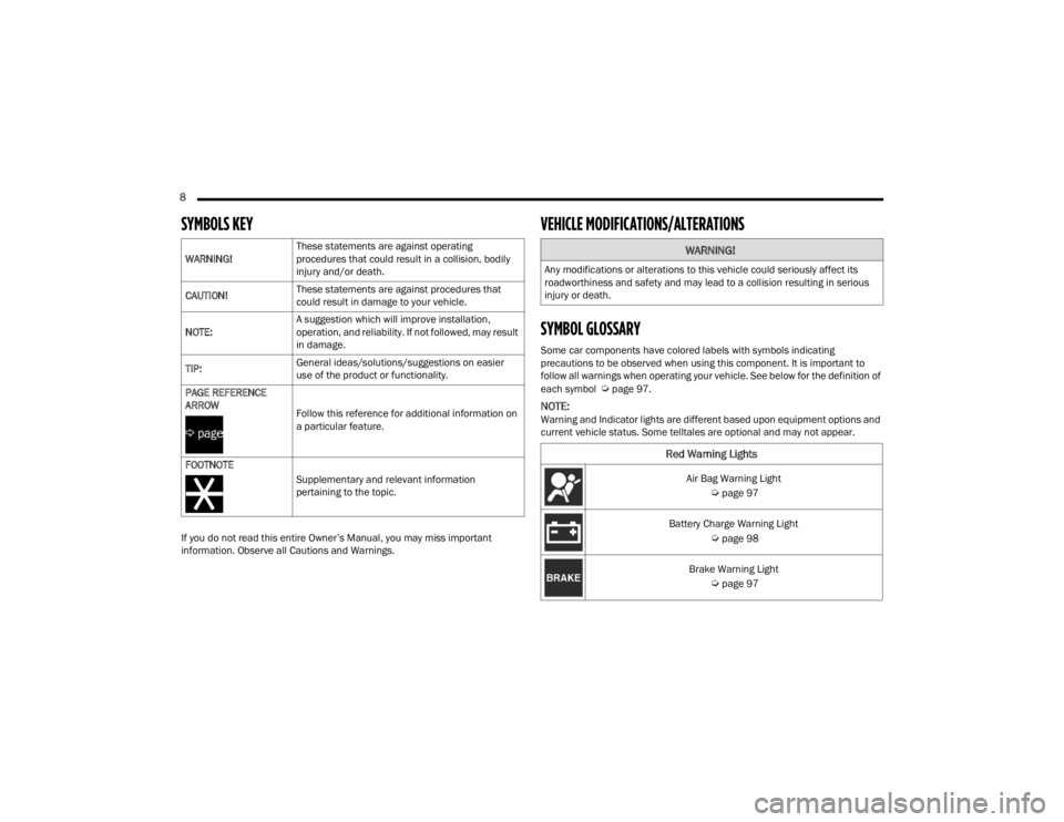
SYMBOLS KEY
If you do not read this entire Owner’s Manual, you may miss important
information. Observe all Cautions and Warnings.
VEHICLE MODIFICATIONS/ALTERATIONS
SYMBOL GLOSSARY
Some car components have colored labels with symbols indicating
precautions to be observed when using this component. It is important to
follow all warnings when operating your vehicle. See below for the definition of
each symbol
Úpage 97.
NOTE:Warning and Indicator lights are different based upon equipment options and
current vehicle status. Some telltales are optional and may not appear.
WARNING!
These statements are against operating
procedures that could result in a collision, bodily
injury and/or death.
CAUTION! These statements are against procedures that
could result in damage to your vehicle.
NOTE: A suggestion which will improve installation,
operation, and reliability. If not followed, may result
in damage.
TIP: General ideas/solutions/suggestions on easier
use of the product or functionality.
PAGE REFERENCE
ARROW Follow this reference for additional information on
a particular feature.
FOOTNOTE Supplementary and relevant information
pertaining to the topic.
WARNING!
Any modifications or alterations to this vehicle could seriously affect its
roadworthiness and safety and may lead to a collision resulting in serious
injury or death.
Red Warning Lights
Air Bag Warning Light
Úpage 97
Battery Charge Warning Light
Úpage 98
Brake Warning Light
Úpage 97
21_RUV_OM_EN_USC_t.book Page 8
Page 11 of 348
9
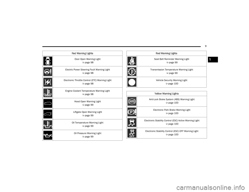
Door Open Warning Light
Úpage 98
Electric Power Steering Fault Warning Light
Úpage 98
Electronic Throttle Control (ETC) Warning Light
Úpage 98
Engine Coolant Temperature Warning Light
Úpage 98
Hood Open Warning Light
Úpage 99
Liftgate Open Warning Light
Úpage 99
Oil Temperature Warning Light
Úpage 99
Oil Pressure Warning Light
Úpage 99
Red Warning Lights
Seat Belt Reminder Warning Light
Úpage 99
Transmission Temperature Warning Light
Úpage 99
Vehicle Security Warning Light
Úpage 100
Yellow Warning Lights
Anti-Lock Brake System (ABS) Warning Light
Úpage 100
Electronic Park Brake Warning Light
Úpage 100
Electronic Stability Control (ESC) Active Warning Light
Úpage 100
Electronic Stability Control (ESC) OFF Warning Light
Úpage 100
Red Warning Lights
1
21_RUV_OM_EN_USC_t.book Page 9
Page 12 of 348
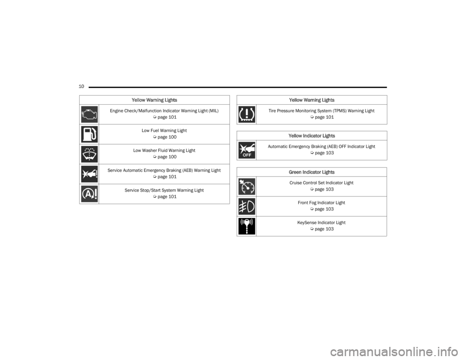
10 Engine Check/Malfunction Indicator Warning Light (MIL)
Úpage 101
Low Fuel Warning Light
Úpage 100
Low Washer Fluid Warning Light
Úpage 100
Service Automatic Emergency Braking (AEB) Warning Light
Úpage 101
Service Stop/Start System Warning Light
Úpage 101
Yellow Warning Lights
Tire Pressure Monitoring System (TPMS) Warning Light
Úpage 101
Yellow Indicator Lights
Automatic Emergency Braking (AEB) OFF Indicator Light
Úpage 103
Green Indicator Lights
Cruise Control Set Indicator Light
Úpage 103
Front Fog Indicator Light
Úpage 103
KeySense Indicator Light
Úpage 103
Yellow Warning Lights
21_RUV_OM_EN_USC_t.book Page 10
Page 19 of 348
GETTING TO KNOW YOUR VEHICLE17
Remote Start is used to defrost windows in cold
weather and to reach a comfortable climate in all
ambient conditions before the customer enters the
vehicle.
NOTE:Obstructions between the vehicle and key fob may
reduce this range Úpage 331.
HOW TO USE REMOTE START
Push and release the Remote Start button on the
key fob twice within five seconds. The vehicle
doors will lock, the parking lights will flash, and the
horn will chirp twice (if programmed). Then, the
engine will start, and the vehicle will remain in the
Remote Start mode for a 15 minute cycle. Pushing the Remote Start button a third time shuts
the engine off.
To drive the vehicle, push the unlock button and
place the ignition in the ON/RUN position.
NOTE:
With Remote Start, the engine will only run for
15 minutes.
Remote Start can only be used twice.
If an engine fault is present or fuel level is
low, the vehicle will start and then shut down
in 10 seconds.
The parking lights will turn on and remain on
during Remote Start mode.
For security, power window operations are
disabled when the vehicle is in the Remote Start
mode.
The ignition must be placed in the ON/RUN posi
-
tion before the Remote Start sequence can be
repeated for a third cycle.
All of the following conditions must be met before
the engine will Remote Start:
Gear selector in PARK
Doors closed
Hood closed
Liftgate closed
Hazard switch off
Brake switch inactive (brake pedal not pressed)
Battery at an acceptable charge level
PANIC button not pushed
System not disabled from previous Remote
Start event
Vehicle Security system indicator flashing
Ignition in OFF position
Fuel level meets minimum requirement
Vehicle Security system is not signaling an intru -
sion
Malfunction Indicator Light (MIL) is not
illuminated
WARNING!
Do not start or run an engine in a closed
garage or confined area. Exhaust gas contains
Carbon Monoxide (CO) which is odorless and
colorless. Carbon Monoxide is poisonous and
can cause serious injury or death when
inhaled.
Keep key fobs away from children. Operation
of the Remote Start system, windows, door
locks or other controls could cause serious
injury or death.WARNING!
Do not start or run an engine in a closed
garage or confined area. Exhaust gas contains
Carbon Monoxide (CO) which is odorless and
colorless. Carbon Monoxide is poisonous and
can cause serious injury or death when
inhaled.
Keep key fobs away from children. Operation
of the Remote Start system, windows, door
locks or other controls could cause serious
injury or death.
2
21_RUV_OM_EN_USC_t.book Page 17
Page 31 of 348
GETTING TO KNOW YOUR VEHICLE29
Manual Seat Height Adjustment
The driver’s seat height can be raised or lowered
by using a lever, located on the outboard side of
the seat. Pump the lever upward to raise the seat
height or pump the lever downward to lower the
seat height.
Manual Front Seat Recline Adjustment
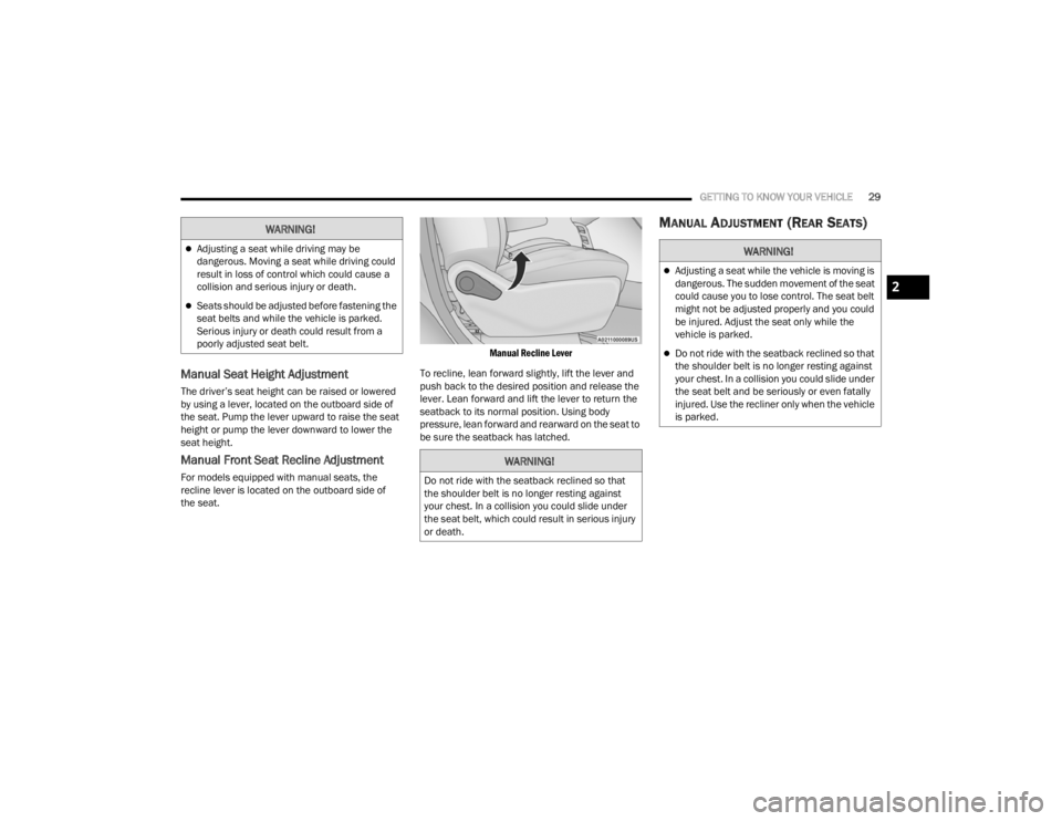
For models equipped with manual seats, the
recline lever is located on the outboard side of
the seat.
Manual Recline Lever
To recline, lean forward slightly, lift the lever and
push back to the desired position and release the
lever. Lean forward and lift the lever to return the
seatback to its normal position. Using body
pressure, lean forward and rearward on the seat to
be sure the seatback has latched.
MANUAL ADJUSTMENT (REAR SEATS)WARNING!
Adjusting a seat while driving may be
dangerous. Moving a seat while driving could
result in loss of control which could cause a
collision and serious injury or death.
Seats should be adjusted before fastening the
seat belts and while the vehicle is parked.
Serious injury or death could result from a
poorly adjusted seat belt.
WARNING!
Do not ride with the seatback reclined so that
the shoulder belt is no longer resting against
your chest. In a collision you could slide under
the seat belt, which could result in serious injury
or death.
WARNING!
Adjusting a seat while the vehicle is moving is
dangerous. The sudden movement of the seat
could cause you to lose control. The seat belt
might not be adjusted properly and you could
be injured. Adjust the seat only while the
vehicle is parked.
Do not ride with the seatback reclined so that
the shoulder belt is no longer resting against
your chest. In a collision you could slide under
the seat belt and be seriously or even fatally
injured. Use the recliner only when the vehicle
is parked.
2
21_RUV_OM_EN_USC_t.book Page 29
Page 32 of 348
30GETTING TO KNOW YOUR VEHICLE
Manual Forward/Rearward Adjustment —
Quad Seats (If Equipped)
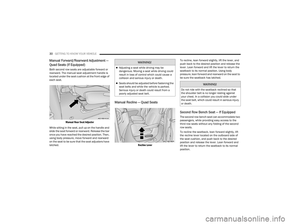
Both second row seats are adjustable forward or
rearward. The manual seat adjustment handle is
located under the seat cushion at the front edge of
each seat.
Manual Rear Seat Adjuster
While sitting in the seat, pull up on the handle and
slide the seat forward or rearward. Release the bar
once you have reached the desired position. Then,
using body pressure, move forward and rearward
on the seat to be sure that the seat adjusters have
latched.
Manual Recline — Quad Seats
Recline Lever
To recline, lean forward slightly, lift the lever, and
push back to the desired position and release the
lever. Lean forward and lift the lever to return the
seatback to its normal position. Using body
pressure, lean forward and rearward on the seat to
be sure the seatback has latched.
Second Row Bench Seat — If Equipped
The second row bench seat can accommodate two
passengers, while providing easy access to the
third row seats without any folding of the second
row seats.
To recline the seatback, lean forward slightly, lift
the recline lever located on the outboard side of
the seat cushion, and push back to the desired
position and release the lever. Lean forward and
lift the lever to return the seatback to its normal
position.
WARNING!
Adjusting a seat while driving may be
dangerous. Moving a seat while driving could
result in loss of control which could cause a
collision and serious injury or death.
Seats should be adjusted before fastening the
seat belts and while the vehicle is parked.
Serious injury or death could result from a
poorly adjusted seat belt.WARNING!
Do not ride with the seatback reclined so that
the shoulder belt is no longer resting against
your chest. In a collision you could slide under
the seat belt, which could result in serious injury
or death.
21_RUV_OM_EN_USC_t.book Page 30
Page 45 of 348
GETTING TO KNOW YOUR VEHICLE43
HEATED SEATS
Front Heated Seats — If Equipped
The front heated seats control buttons are located
in the touchscreen.
You can choose from HI, LO or off heat settings.
The indicator lights in each switch indicate the
level of heat in use. Two indicator lights will
illuminate for HI, one for LO and none for off.
Press the heated seat button once to turn
the HI setting on.
Press the heated seat button a second time
to turn the LO setting on.
Press the heated seat button a third time to
turn the heating elements off.
The level of heat selected will stay on until the
operator changes it.
NOTE:
Once a heat setting is selected, heat will be felt
within two to five minutes.
The engine must be running for the heated
seats to operate.
For information on use with the Remote Start
system, see
Úpage 18.
ADJUSTABLE ARMREST (FRONT SEATS)
— I
F EQUIPPED
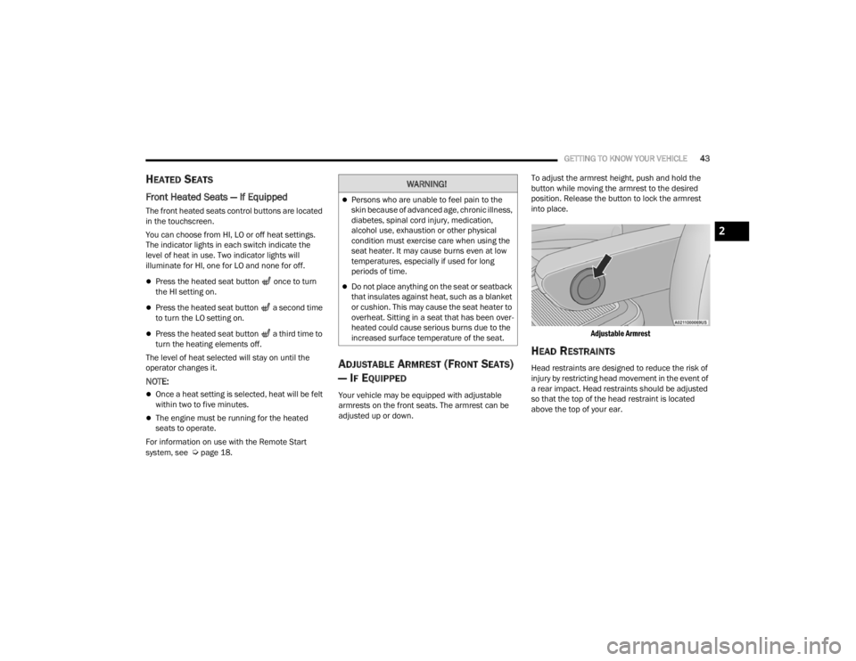
Your vehicle may be equipped with adjustable
armrests on the front seats. The armrest can be
adjusted up or down. To adjust the armrest height, push and hold the
button while moving the armrest to the desired
position. Release the button to lock the armrest
into place.
Adjustable Armrest
HEAD RESTRAINTS
Head restraints are designed to reduce the risk of
injury by restricting head movement in the event of
a rear impact. Head restraints should be adjusted
so that the top of the head restraint is located
above the top of your ear.
WARNING!
Persons who are unable to feel pain to the
skin because of advanced age, chronic illness,
diabetes, spinal cord injury, medication,
alcohol use, exhaustion or other physical
condition must exercise care when using the
seat heater. It may cause burns even at low
temperatures, especially if used for long
periods of time.
Do not place anything on the seat or seatback
that insulates against heat, such as a blanket
or cushion. This may cause the seat heater to
overheat. Sitting in a seat that has been over -
heated could cause serious burns due to the
increased surface temperature of the seat.
2
21_RUV_OM_EN_USC_t.book Page 43
Page 51 of 348
GETTING TO KNOW YOUR VEHICLE49
CONVERSATION MIRROR
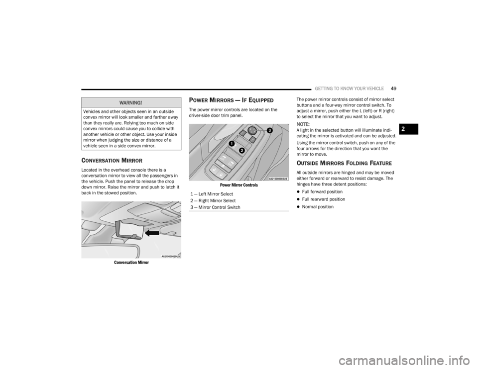
Located in the overhead console there is a
conversation mirror to view all the passengers in
the vehicle. Push the panel to release the drop
down mirror. Raise the mirror and push to latch it
back in the stowed position.
Conversation Mirror
POWER MIRRORS — IF EQUIPPED
The power mirror controls are located on the
driver-side door trim panel.
Power Mirror Controls
The power mirror controls consist of mirror select
buttons and a four-way mirror control switch. To
adjust a mirror, push either the L (left) or R (right)
to select the mirror that you want to adjust.
NOTE:A light in the selected button will illuminate indi
-
cating the mirror is activated and can be adjusted.
Using the mirror control switch, push on any of the
four arrows for the direction that you want the
mirror to move.
OUTSIDE MIRRORS FOLDING FEATURE
All outside mirrors are hinged and may be moved
either forward or rearward to resist damage. The
hinges have three detent positions:
Full forward position
Full rearward position
Normal position
WARNING!
Vehicles and other objects seen in an outside
convex mirror will look smaller and farther away
than they really are. Relying too much on side
convex mirrors could cause you to collide with
another vehicle or other object. Use your inside
mirror when judging the size or distance of a
vehicle seen in a side convex mirror.
1 — Left Mirror Select
2 — Right Mirror Select
3 — Mirror Control Switch
2
21_RUV_OM_EN_USC_t.book Page 49
Page 53 of 348
GETTING TO KNOW YOUR VEHICLE51
Non-rolling Code Devices
Most devices manufactured before 1995 will not
have a rolling code. These devices will also not
have a “LEARN” or “TRAIN” button.
PROGRAMMING HOMELINK® TO A
G
ARAGE DOOR OPENER
To program any of the HomeLink® buttons to
activate your garage door opener motor, follow the
steps below:
NOTE:All HomeLink® buttons are programmed using this
procedure. You do not need to erase all channels
when programming additional buttons.
1. Place the ignition switch into the ON/RUN
position.
2. Place the garage door opener transmitter 1 to 3 inches (3 to 8 cm) away from the
HomeLink® button you wish to program, while
keeping the HomeLink® indicator light in view.
3. Push and hold the HomeLink® button you want to program while you push and hold the
garage door opener transmitter button you are
trying to replicate.
4. Continue to hold both buttons and observe the HomeLink® indicator light. The
HomeLink® indicator light will flash slowly and
then rapidly. Once this happens, release both
buttons.
NOTE:Make sure the garage door opener motor is
plugged in before moving on to the rolling
code/non-rolling code final steps.
Rolling Code Garage Door Opener Final Steps
NOTE:You have 30 seconds in which to initiate rolling
code final step 2, after completing rolling code
final step 1.
1. At the garage door opener motor (in the garage), locate the “LEARN” or “TRAIN”
button. This can usually be found where the
hanging antenna wire is attached to the
garage door opener motor. Firmly push and
release the “LEARN” or “TRAIN” button.
2. Return to the vehicle and push the programmed HomeLink® button three times
(holding the button for two seconds each
time). If the garage door opener motor
operates, programming is complete.
3. Push the programmed HomeLink® button to confirm that the garage door opener motor
operates. If the garage door opener motor
does not operate, repeat the final steps for the
rolling code procedure. Non-Rolling Code Garage Door Opener Final Steps
1. Push and hold the programmed HomeLink®
button and observe the HomeLink® indicator
light. If the HomeLink® indicator light stays
on constantly, programming is complete.
2. Push the programmed HomeLink® button to confirm that the garage door opener motor
operates. If the garage door opener motor
does not operate, repeat the steps from the
beginning.
WARNING!
Your motorized door or gate will open and
close while you are programming the universal
transceiver. Do not program the transceiver
if people or pets are in the path of the door
or gate.
Do not run your vehicle in a closed garage or
confined area while programming the trans -
ceiver. Exhaust gas from your vehicle contains
Carbon Monoxide (CO) which is odorless and
colorless. Carbon Monoxide is poisonous
when inhaled and can cause you and others to
be severely injured or killed.
2
21_RUV_OM_EN_USC_t.book Page 51