CHRYSLER VOYAGER 2022 Manual PDF
Manufacturer: CHRYSLER, Model Year: 2022, Model line: VOYAGER, Model: CHRYSLER VOYAGER 2022Pages: 316, PDF Size: 17.41 MB
Page 71 of 316
GETTING TO KNOW YOUR VEHICLE69
SEAT STORAGE BIN COVER EMERGENCY
RELEASE LEVER
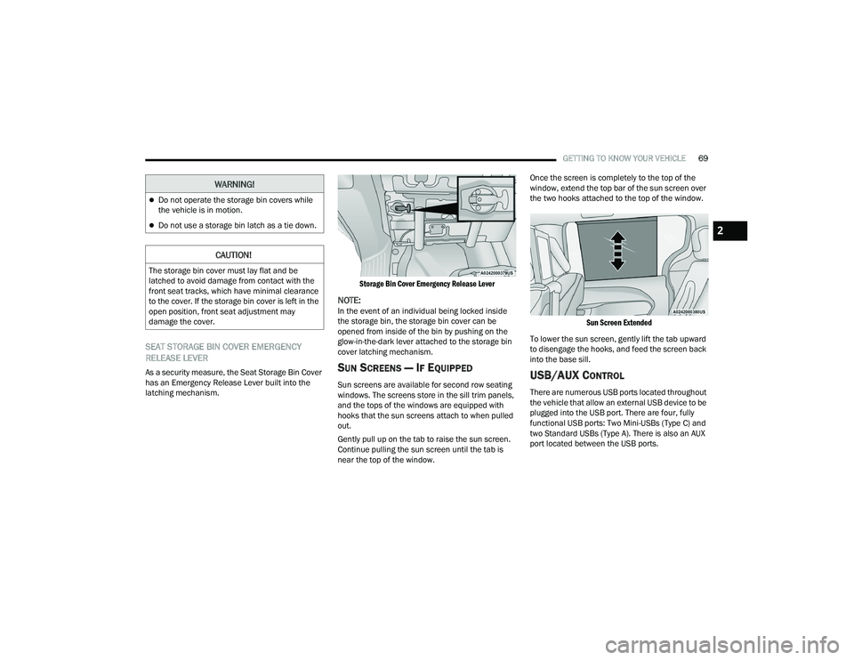
As a security measure, the Seat Storage Bin Cover
has an Emergency Release Lever built into the
latching mechanism.
Storage Bin Cover Emergency Release Lever
NOTE:In the event of an individual being locked inside
the storage bin, the storage bin cover can be
opened from inside of the bin by pushing on the
glow-in-the-dark lever attached to the storage bin
cover latching mechanism.
SUN SCREENS — IF EQUIPPED
Sun screens are available for second row seating
windows. The screens store in the sill trim panels,
and the tops of the windows are equipped with
hooks that the sun screens attach to when pulled
out.
Gently pull up on the tab to raise the sun screen.
Continue pulling the sun screen until the tab is
near the top of the window.Once the screen is completely to the top of the
window, extend the top bar of the sun screen over
the two hooks attached to the top of the window.
Sun Screen Extended
To lower the sun screen, gently lift the tab upward
to disengage the hooks, and feed the screen back
into the base sill.USB/AUX CONTROL
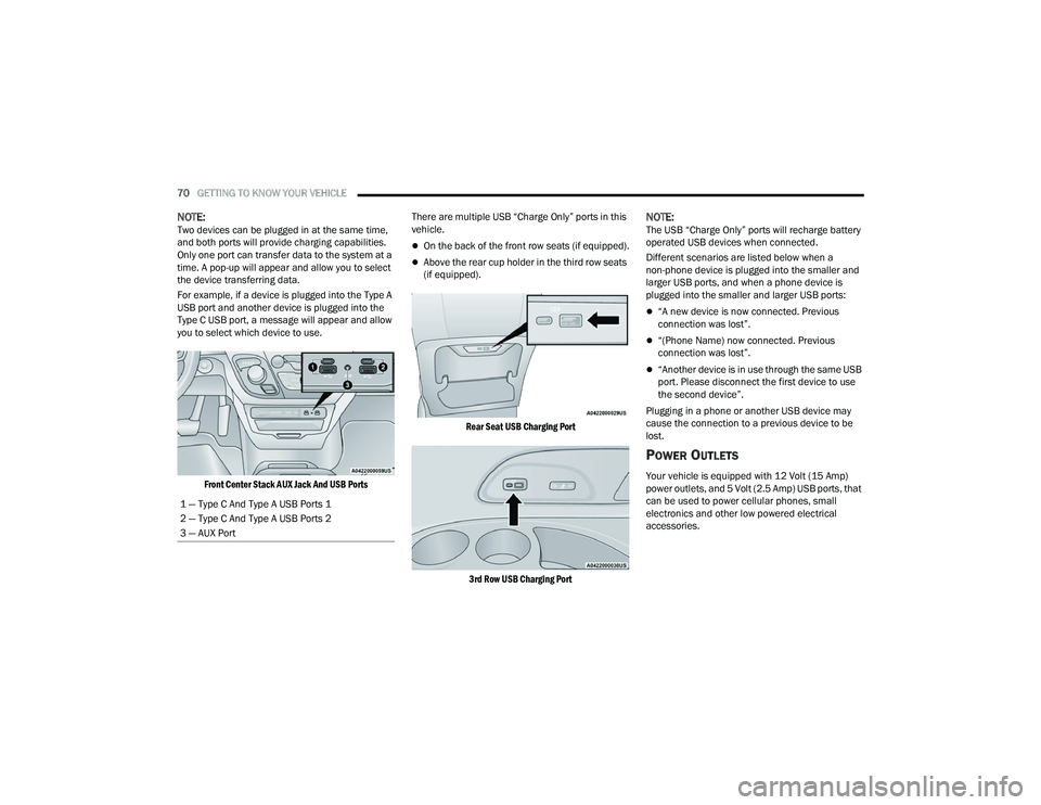
There are numerous USB ports located throughout
the vehicle that allow an external USB device to be
plugged into the USB port. There are four, fully
functional USB ports: Two Mini-USBs (Type C) and
two Standard USBs (Type A). There is also an AUX
port located between the USB ports.
Do not operate the storage bin covers while
the vehicle is in motion.
Do not use a storage bin latch as a tie down.
CAUTION!
The storage bin cover must lay flat and be
latched to avoid damage from contact with the
front seat tracks, which have minimal clearance
to the cover. If the storage bin cover is left in the
open position, front seat adjustment may
damage the cover.
WARNING!
2
22_RUVG_OM_EN_USC_t.book Page 69
Page 72 of 316
70GETTING TO KNOW YOUR VEHICLE
NOTE:Two devices can be plugged in at the same time,
and both ports will provide charging capabilities.
Only one port can transfer data to the system at a
time. A pop-up will appear and allow you to select
the device transferring data.
For example, if a device is plugged into the Type A
USB port and another device is plugged into the
Type C USB port, a message will appear and allow
you to select which device to use.
Front Center Stack AUX Jack And USB Ports
There are multiple USB “Charge Only” ports in this
vehicle.
On the back of the front row seats (if equipped).
Above the rear cup holder in the third row seats
(if equipped).
Rear Seat USB Charging Port
3rd Row USB Charging Port
NOTE:The USB “Charge Only” ports will recharge battery
operated USB devices when connected.
Different scenarios are listed below when a
non-phone device is plugged into the smaller and
larger USB ports, and when a phone device is
plugged into the smaller and larger USB ports:
“A new device is now connected. Previous
connection was lost”.
“(Phone Name) now connected. Previous
connection was lost”.
“Another device is in use through the same USB
port. Please disconnect the first device to use
the second device”.
Plugging in a phone or another USB device may
cause the connection to a previous device to be
lost.
POWER OUTLETS
Your vehicle is equipped with 12 Volt (15 Amp)
power outlets, and 5 Volt (2.5 Amp) USB ports, that
can be used to power cellular phones, small
electronics and other low powered electrical
accessories.
1 — Type C And Type A USB Ports 1
2 — Type C And Type A USB Ports 2
3 — AUX Port
22_RUVG_OM_EN_USC_t.book Page 70
Page 73 of 316
GETTING TO KNOW YOUR VEHICLE71
The power outlets can be labeled with either a
“key” or a “battery” symbol to indicate how the
outlet is powered. Power outlets labeled with a
“key” are powered when the ignition is in the
ON/RUN or ACC position, while the outlets labeled
with a “battery” are connected directly to the
battery and powered at all times.
NOTE:All accessories connected to the “battery” powered
outlets should be removed or turned off when the
vehicle is not in use to protect the battery against
discharge.
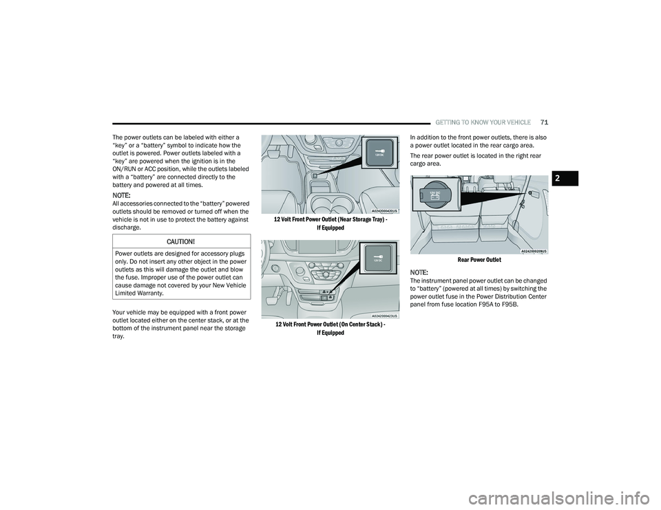
Your vehicle may be equipped with a front power
outlet located either on the center stack, or at the
bottom of the instrument panel near the storage
tray.
12 Volt Front Power Outlet (Near Storage Tray) -
If Equipped
12 Volt Front Power Outlet (On Center Stack) - If Equipped
In addition to the front power outlets, there is also
a power outlet located in the rear cargo area.
The rear power outlet is located in the right rear
cargo area.
Rear Power Outlet
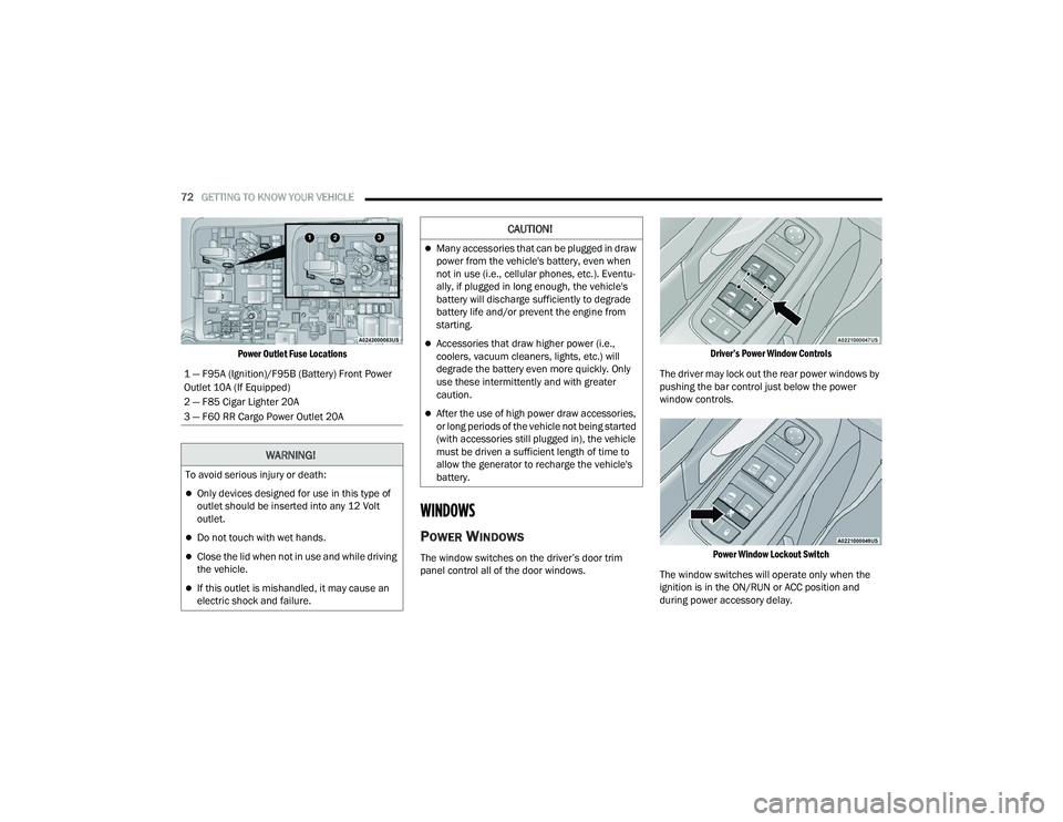
NOTE:The instrument panel power outlet can be changed
to “battery” (powered at all times) by switching the
power outlet fuse in the Power Distribution Center
panel from fuse location F95A to F95B.
CAUTION!
Power outlets are designed for accessory plugs
only. Do not insert any other object in the power
outlets as this will damage the outlet and blow
the fuse. Improper use of the power outlet can
cause damage not covered by your New Vehicle
Limited Warranty.
2
22_RUVG_OM_EN_USC_t.book Page 71
Page 74 of 316
72GETTING TO KNOW YOUR VEHICLE
Power Outlet Fuse Locations
WINDOWS
POWER WINDOWS
The window switches on the driver’s door trim
panel control all of the door windows.
Driver’s Power Window Controls
The driver may lock out the rear power windows by
pushing the bar control just below the power
window controls.
Power Window Lockout Switch
The window switches will operate only when the
ignition is in the ON/RUN or ACC position and
during power accessory delay.
1 — F95A (Ignition)/F95B (Battery) Front Power
Outlet 10A (If Equipped)
2 — F85 Cigar Lighter 20A
3 — F60 RR Cargo Power Outlet 20A
WARNING!
To avoid serious injury or death:
Only devices designed for use in this type of
outlet should be inserted into any 12 Volt
outlet.
Do not touch with wet hands.
Close the lid when not in use and while driving
the vehicle.
If this outlet is mishandled, it may cause an
electric shock and failure.
CAUTION!
Many accessories that can be plugged in draw
power from the vehicle's battery, even when
not in use (i.e., cellular phones, etc.). Eventu
-
ally, if plugged in long enough, the vehicle's
battery will discharge sufficiently to degrade
battery life and/or prevent the engine from
starting.
Accessories that draw higher power (i.e.,
coolers, vacuum cleaners, lights, etc.) will
degrade the battery even more quickly. Only
use these intermittently and with greater
caution.
After the use of high power draw accessories,
or long periods of the vehicle not being started
(with accessories still plugged in), the vehicle
must be driven a sufficient length of time to
allow the generator to recharge the vehicle's
battery.
22_RUVG_OM_EN_USC_t.book Page 72
Page 75 of 316
GETTING TO KNOW YOUR VEHICLE73
NOTE:Power Window controls will also remain active for
up to 10 minutes after the ignition has been
placed in the OFF position, depending upon the
accessory delay setting. Opening a front door will
cancel this feature.
There is a single control on the front passenger’s
door trim panel which operates the passenger door
window and a set of controls that lock and unlock
all doors. The controls will operate only when the
ignition is in the ON/RUN or ACC position and
during power accessory delay.
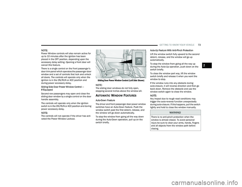
Sliding Side Door Power Window Control —
If Equipped
Second row passengers may open and close the
sliding door window by a single control on the door
handle assembly.
The controls will operate only when the ignition
switch is in the ON/RUN or ACC position and during
power accessory delay.
NOTE:The controls will not operate if the driver has acti-
vated the Power Window Lockout.
Sliding Door Power Window Control (Left Side Shown)
NOTE:The sliding door windows do not fully open,
stopping several inches above the window sill.
AUTOMATIC WINDOW FEATURES
Auto-Down Feature
The driver and front passenger door power window
switches have an Auto-Down feature. Push the
window switch past the first detent, release, and
the window will go down automatically.
To stop the window from going all the way down
during the Auto-Down operation, pull up on the
switch briefly.Auto-Up Feature With Anti-Pinch Protection
Lift the window switch fully upward to the second
detent, release, and the window will go up
automatically.
To stop the window from going all the way up
during the Auto-Up operation, push down on the
switch briefly.
To close the window part way, lift the window
switch briefly and release it when you want the
window to stop.
If the window runs into any obstacle during
auto-closure, it will reverse direction and then go
back down. Remove the obstacle and use the
window switch again to close the window.
NOTE:Any impact due to rough road conditions may
trigger the auto-reverse function unexpectedly
during auto-closure. If this happens, pull the switch
lightly and hold to close the window manually.
WARNING!
There is no anti-pinch protection when the
window is almost closed. To avoid personal
injury be sure to clear your arms, hands, fingers
and all objects from the window path before
closing.
2
22_RUVG_OM_EN_USC_t.book Page 73
Page 76 of 316
74GETTING TO KNOW YOUR VEHICLE
RESET AUTO UP
To reactivate the Auto Up feature, perform the
following steps after vehicle power is restored:
1. Pull the window control up to close the
window completely and continue to hold the
control up for an additional two seconds after
the window is closed.
2. Push the window control down firmly to the second detent to open the window completely
and continue to hold the control down for an
additional two seconds after the window is
fully open.
WIND BUFFETING
Wind buffeting can be described as the perception
of pressure on the ears or a helicopter-type sound
in the ears. Your vehicle may exhibit wind buffeting
with the windows down, or the sunroof (if
equipped) in certain open or partially open
positions. This is a normal occurrence and can be
minimized. If the buffeting occurs with the rear
windows open, open the front and rear windows
together to minimize the buffeting. If the buffeting
occurs with the sunroof open, adjust the sunroof
opening to minimize the buffeting or open any
window.
HOOD
OPENING
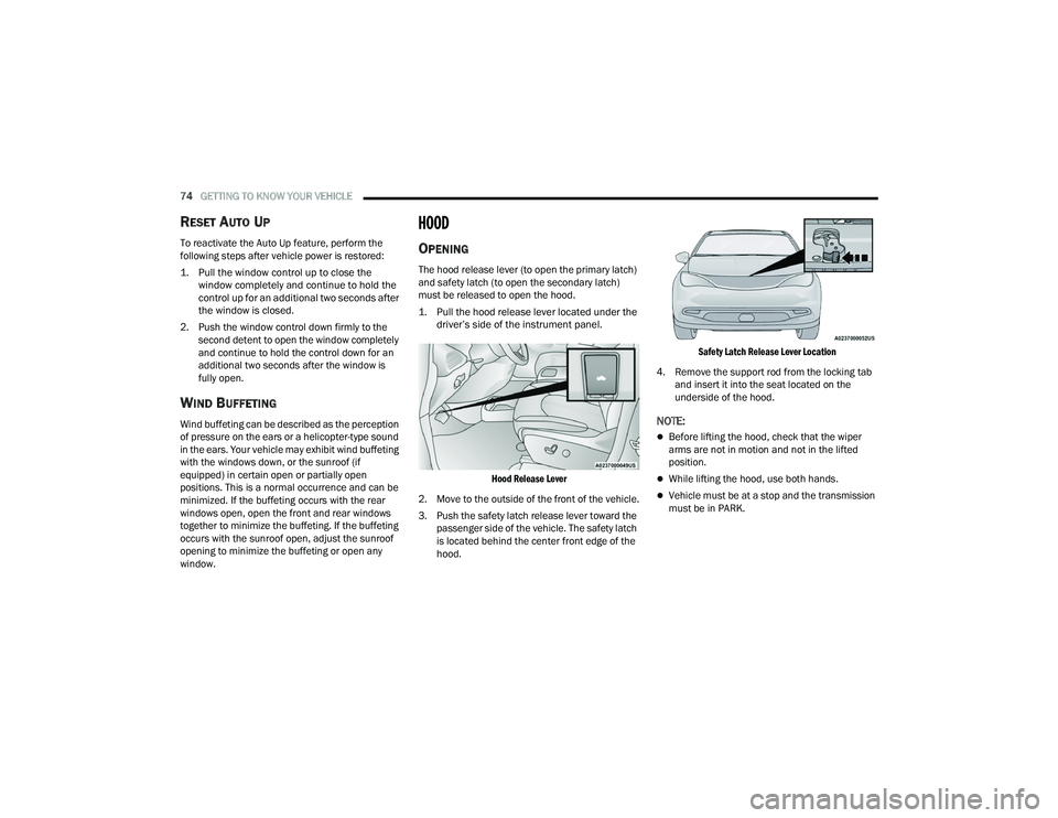
The hood release lever (to open the primary latch)
and safety latch (to open the secondary latch)
must be released to open the hood.
1. Pull the hood release lever located under the driver’s side of the instrument panel.
Hood Release Lever
2. Move to the outside of the front of the vehicle.
3. Push the safety latch release lever toward the passenger side of the vehicle. The safety latch
is located behind the center front edge of the
hood.
Safety Latch Release Lever Location
4. Remove the support rod from the locking tab and insert it into the seat located on the
underside of the hood.
NOTE:
Before lifting the hood, check that the wiper
arms are not in motion and not in the lifted
position.
While lifting the hood, use both hands.
Vehicle must be at a stop and the transmission
must be in PARK.
22_RUVG_OM_EN_USC_t.book Page 74
Page 77 of 316
GETTING TO KNOW YOUR VEHICLE75
CLOSING
1. Hold up the hood with one hand and with the
other hand remove the support rod from its
seat and reinsert it into the locking tab.
2. Lower the hood to approximately 12 inches (30 cm) from the engine compartment and
drop it. Make sure that the hood is completely
closed.
LIFTGATE
TO UNLOCK/OPEN THE LIFTGATE
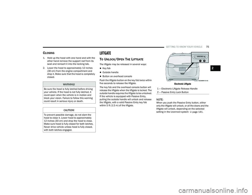
The liftgate may be released in several ways:
Key fob
Outside handle
Button on overhead console
Push the liftgate button on the key fob twice within
five seconds to release the liftgate.
The key fob and the overhead console button will
release the liftgate when the liftgate is locked. The
outside handle requires the liftgate to be unlocked.
If the vehicle is equipped with Passive Entry,
pulling the outside handle will unlock and release
the liftgate, with a valid Passive Entry key fob
within 5 ft (1.5 m) of the liftgate.
Electronic Liftgate
NOTE:When you push the Passive Entry button, either
only the liftgate will unlock, or all the doors and the
liftgate will unlock, depending on the selected
setting in the Uconnect system
Úpage 141.
WARNING!
Be sure the hood is fully latched before driving
your vehicle. If the hood is not fully latched, it
could open when the vehicle is in motion and
block your vision. Failure to follow this warning
could result in serious injury or death.
CAUTION!
To prevent possible damage, do not slam the
hood to close it. Lower hood to approximately
12 inches (30 cm) and drop the hood to close.
Make sure hood is fully closed for both latches.
Never drive vehicle unless hood is fully closed,
with both latches engaged.
1 — Electronic Liftgate Release Handle
2 — Passive Entry Lock Button
2
22_RUVG_OM_EN_USC_t.book Page 75
Page 78 of 316
76GETTING TO KNOW YOUR VEHICLE
TO LOCK/CLOSE THE LIFTGATE
To manually close the liftgate, grab the liftgate
closing handle and pull in a downward motion.
With a valid Passive Entry key fob within 5 ft
(1.5 m) of the liftgate, push the Passive Entry lock
button located to the right of the outside handle to
lock the vehicle.
POWER LIFTGATE — IF EQUIPPED
The power liftgate may be opened or closed in
several ways:
Overhead console liftgate button
Key fob
Outside handle (opens liftgate only)
Rear interior power liftgate switch on the upper
left trim (when liftgate is open)
Using the above ways to open or close the liftgate:
When the liftgate is fully closed, the liftgate will
open
When the liftgate is fully open, the liftgate will
close
When the liftgate is moving, the liftgate will
reverse
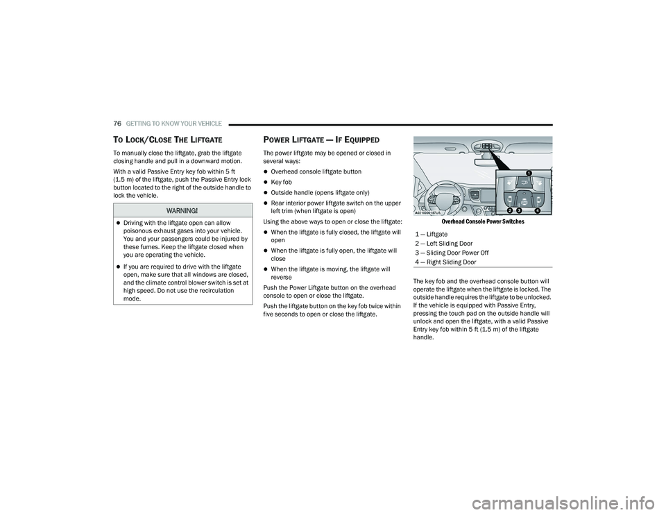
Push the Power Liftgate button on the overhead
console to open or close the liftgate.
Push the liftgate button on the key fob twice within
five seconds to open or close the liftgate.
Overhead Console Power Switches
The key fob and the overhead console button will
operate the liftgate when the liftgate is locked. The
outside handle requires the liftgate to be unlocked.
If the vehicle is equipped with Passive Entry,
pressing the touch pad on the outside handle will
unlock and open the liftgate, with a valid Passive
Entry key fob within 5 ft (1.5 m) of the liftgate
handle.
WARNING!
Driving with the liftgate open can allow
poisonous exhaust gases into your vehicle.
You and your passengers could be injured by
these fumes. Keep the liftgate closed when
you are operating the vehicle.
If you are required to drive with the liftgate
open, make sure that all windows are closed,
and the climate control blower switch is set at
high speed. Do not use the recirculation
mode.
1 — Liftgate
2 — Left Sliding Door
3 — Sliding Door Power Off
4 — Right Sliding Door
22_RUVG_OM_EN_USC_t.book Page 76
Page 79 of 316
GETTING TO KNOW YOUR VEHICLE77
NOTE:Tones are sounded and the turn signals are
flashed with liftgate movements. These alerts can
be turned on or off in Uconnect Settings
Úpage 141.
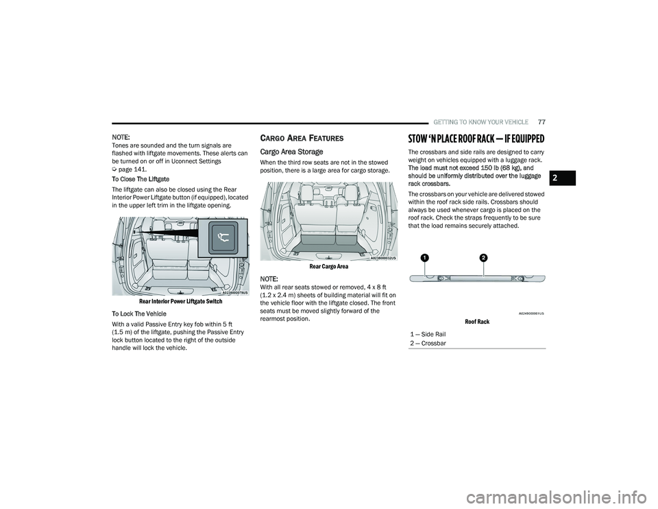
To Close The Liftgate
The liftgate can also be closed using the Rear
Interior Power Liftgate button (if equipped), located
in the upper left trim in the liftgate opening.
Rear Interior Power Liftgate Switch
To Lock The Vehicle
With a valid Passive Entry key fob within 5 ft
(1.5 m) of the liftgate, pushing the Passive Entry
lock button located to the right of the outside
handle will lock the vehicle.
CARGO AREA FEATURES
Cargo Area Storage
When the third row seats are not in the stowed
position, there is a large area for cargo storage.
Rear Cargo Area
NOTE:With all rear seats stowed or removed, 4 x 8 ft
(1.2 x 2.4 m) sheets of building material will fit on
the vehicle floor with the liftgate closed. The front
seats must be moved slightly forward of the
rearmost position.
STOW ‘N PLACE ROOF RACK — IF EQUIPPED
The crossbars and side rails are designed to carry
weight on vehicles equipped with a luggage rack.
The load must not exceed 150 lb (68 kg), and
should be uniformly distributed over the luggage
rack crossbars.
The crossbars on your vehicle are delivered stowed
within the roof rack side rails. Crossbars should
always be used whenever cargo is placed on the
roof rack. Check the straps frequently to be sure
that the load remains securely attached.
Roof Rack
1 — Side Rail
2 — Crossbar
2
22_RUVG_OM_EN_USC_t.book Page 77
Page 80 of 316

78GETTING TO KNOW YOUR VEHICLE
The Stow ‘N Place roof rack does not increase the
total load carrying capacity of the vehicle. Be sure
the total load of cargo inside the vehicle plus that
on the external rack does not exceed the maximum
vehicle load capacity.
DEPLOYING THE CROSSBARS
1. To deploy the crossbars, completely loosen the thumb screws at both ends of the
crossbar and lift the crossbar from its stowed
position in the side rail. Repeat with crossbar
on the opposite side.
Thumb Screw
NOTE:The thumb screws cannot be fully removed.
Removing Crossbars
2. Bend the crossbar supports at each end,
taking care to keep hand clear of pivoting joint.
Slide the thumb screw down.
Bending Pivot
3. Position the crossbars across the roof making sure the letters on the crossbars align with the
matching letters on the side rail.
CAUTION!
Use care when removing and handling the
crossbars to prevent damage to the vehicle.
22_RUVG_OM_EN_USC_t.book Page 78