engine CHRYSLER VOYAGER 2023 User Guide
[x] Cancel search | Manufacturer: CHRYSLER, Model Year: 2023, Model line: VOYAGER, Model: CHRYSLER VOYAGER 2023Pages: 256, PDF Size: 13.97 MB
Page 24 of 256
22GETTING TO KNOW YOUR VEHICLE
To avoid unintentional operation of the power sliding
door from the rear seats, push the Sliding Door Power
Off button, located in the overhead console. When the
overhead console power OFF LED is lit, the sliding door
may not be power opened or closed when pushing the
buttons just inside the sliding doors, or when pulling on
the handles.
To Disengage The Child Protection Door Lock
1. Open the sliding side door.
2. Slide the Child Protection Door Lock control outward (away from the vehicle) to disengage the Child
Protection Door Lock.
3. Repeat Steps 1 and 2 on the opposite sliding door.
NOTE:After disengaging (or engaging) the Child Protection Door
Lock, always test the inside door handle with the sliding
door closed to make certain the Child Protection Door
Lock is in the desired position. The inside door handle will
open the sliding door when the Child Protection Door Lock
is disengaged.
STEERING WHEEL
TILT/TELESCOPING STEERING COLUMN
This feature allows you to tilt the steering column upward
or downward. It also allows you to lengthen or shorten the
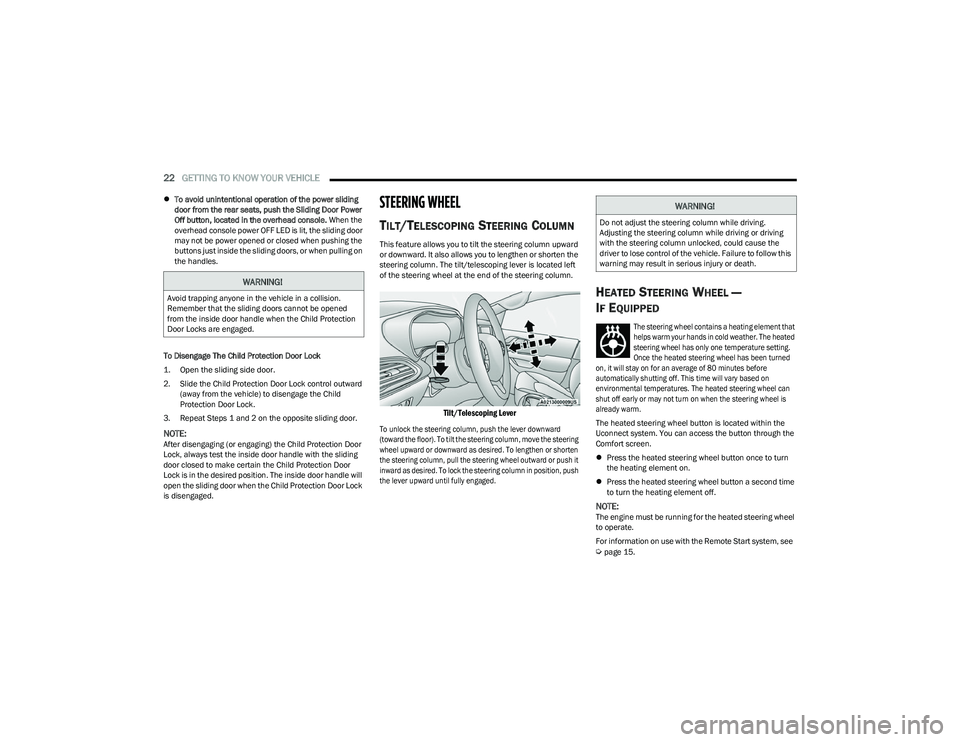
steering column. The tilt/telescoping lever is located left
of the steering wheel at the end of the steering column.
Tilt/Telescoping Lever
To unlock the steering column, push the lever downward
(toward the floor). To tilt the steering column, move the steering
wheel upward or downward as desired. To lengthen or shorten
the steering column, pull the steering wheel outward or push it
inward as desired. To lock the steering column in position, push
the lever upward until fully engaged.
HEATED STEERING WHEEL —
I
F EQUIPPED
The steering wheel contains a heating element that
helps warm your hands in cold weather. The heated
steering wheel has only one temperature setting.
Once the heated steering wheel has been turned
on, it will stay on for an average of 80 minutes before
automatically shutting off. This time will vary based on
environmental temperatures. The heated steering wheel can
shut off early or may not turn on when the steering wheel is
already warm.
The heated steering wheel button is located within the
Uconnect system. You can access the button through the
Comfort screen.
Press the heated steering wheel button once to turn
the heating element on.
Press the heated steering wheel button a second time
to turn the heating element off.
NOTE:The engine must be running for the heated steering wheel
to operate.
For information on use with the Remote Start system, see
Úpage 15.
WARNING!
Avoid trapping anyone in the vehicle in a collision.
Remember that the sliding doors cannot be opened
from the inside door handle when the Child Protection
Door Locks are engaged.
WARNING!
Do not adjust the steering column while driving.
Adjusting the steering column while driving or driving
with the steering column unlocked, could cause the
driver to lose control of the vehicle. Failure to follow this
warning may result in serious injury or death.
23_RUV_OM_EN_US_t.book Page 22
Page 36 of 256

34GETTING TO KNOW YOUR VEHICLE
Tilting The Seat Up Or Down
The angle of the seat cushion can be adjusted in two
directions. Pull upward or push downward on the front of
the seat switch, the front of the seat cushion will move in
the direction of the switch. Release the switch when the
desired position has been reached.
Reclining The Seatback
The angle of the seatback can be adjusted forward or
rearward. Push the seatback switch forward or rearward,
the seat will move in the direction of the switch. Release
the switch when the desired position is reached.
Power Lumbar — If Equipped
Power Lumbar Switch Location
The front driver’s seat may be equipped with a four-way
lumbar adjustment. The power lumbar switch is located on
the outboard side of the equipped power seat. Push the
switch forward or rearward to increase or decrease the
lumbar support. Push the switch upward or downward to
raise or lower the lumbar support.
HEATED SEATS
Front Heated Seats — If Equipped
The front heated seats control buttons are
located in the touchscreen.
You can choose from HI, LO or off heat settings.
The indicator lights in each switch indicate the level of
heat in use. Two indicator lights will illuminate for HI, one
for LO and none for off.
Press the heated seat button once to turn the HI setting on.
Press the heated seat button a second time to turn the
LO setting on.
Press the heated seat button a third time to turn the
heating elements off.
The level of heat selected will stay on until the operator
changes it.
NOTE:
Once a heat setting is selected, heat will be felt within
two to five minutes.
The engine must be running for the heated seats to
operate.
For information on use with the Remote Start system, see
Úpage 15.
WARNING!
Adjusting a seat while driving may be dangerous.
Moving a seat while driving could result in loss of
control which could cause a collision and serious
injury or death.
Seats should be adjusted before fastening the seat belts
and while the vehicle is parked. Serious injury or death
could result from a poorly adjusted seat belt.
Do not ride with the seatback reclined so that the
shoulder belt is no longer resting against your chest.
In a collision you could slide under the seat belt,
which could result in serious injury or death.
CAUTION!
Do not place any article under a power seat or impede
its ability to move as it may cause damage to the seat
controls. Seat travel may become limited if movement
is stopped by an obstruction in the seat's path.
WARNING!
Persons who are unable to feel pain to the skin
because of advanced age, chronic illness, diabetes,
spinal cord injury, medication, alcohol use, exhaus -
tion or other physical condition must exercise care
when using the seat heater. It may cause burns even
at low temperatures, especially if used for long
periods of time.
Do not place anything on the seat or seatback that
insulates against heat, such as a blanket or cushion.
This may cause the seat heater to overheat. Sitting in
a seat that has been overheated could cause serious
burns due to the increased surface temperature of
the seat.
23_RUV_OM_EN_US_t.book Page 34
Page 42 of 256
40GETTING TO KNOW YOUR VEHICLE
Headlight Switch (Vehicles Sold In Canada Only)
NOTE:
Vehicles sold in Canada are equipped with a headlight
switch with an AUTO and ON detent but without an OFF
detent. Headlights will be deactivated when the headlight
switch is placed in the parking lights position. However,
the Daytime Running Lights (DRLs) will be activated along
with the front and rear marker lights. The DRLs may be
deactivated when the parking brake is engaged.
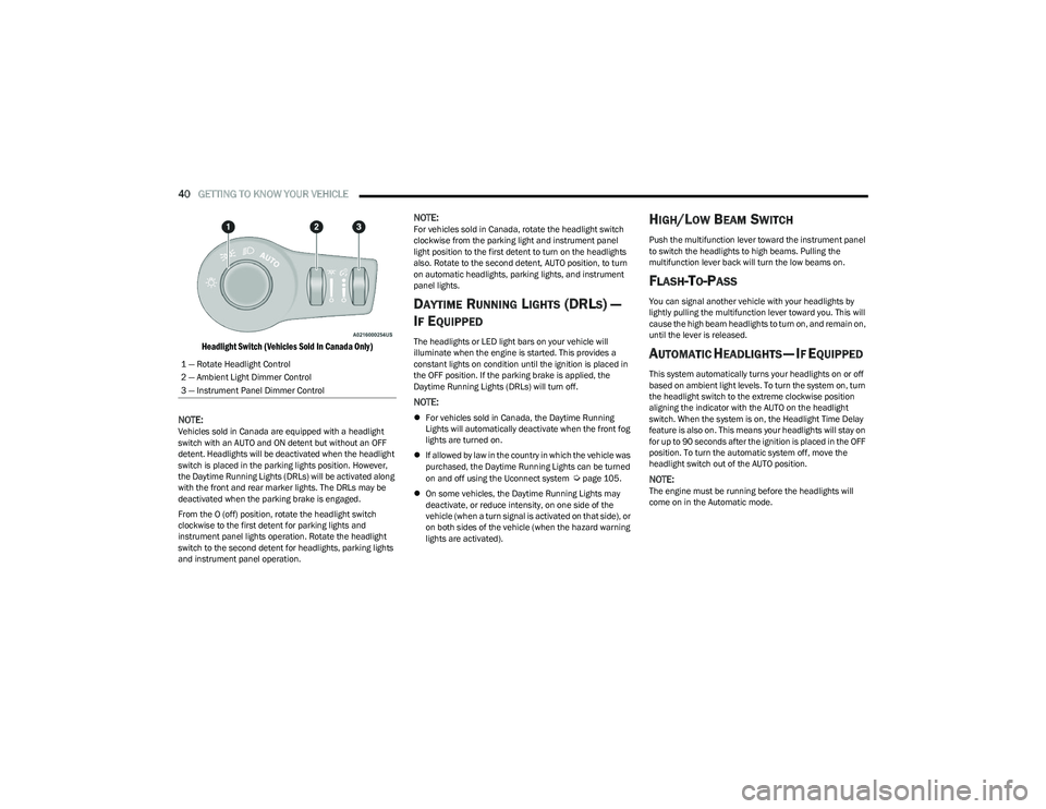
From the O (off) position, rotate the headlight switch
clockwise to the first detent for parking lights and
instrument panel lights operation. Rotate the headlight
switch to the second detent for headlights, parking lights
and instrument panel operation.
NOTE:For vehicles sold in Canada, rotate the headlight switch
clockwise from the parking light and instrument panel
light position to the first detent to turn on the headlights
also. Rotate to the second detent, AUTO position, to turn
on automatic headlights, parking lights, and instrument
panel lights.
DAYTIME RUNNING LIGHTS (DRLS) —
I
F EQUIPPED
The headlights or LED light bars on your vehicle will
illuminate when the engine is started. This provides a
constant lights on condition until the ignition is placed in
the OFF position. If the parking brake is applied, the
Daytime Running Lights (DRLs) will turn off.
NOTE:
For vehicles sold in Canada, the Daytime Running
Lights will automatically deactivate when the front fog
lights are turned on.
If allowed by law in the country in which the vehicle was
purchased, the Daytime Running Lights can be turned
on and off using the Uconnect system
Úpage 105.
On some vehicles, the Daytime Running Lights may
deactivate, or reduce intensity, on one side of the
vehicle (when a turn signal is activated on that side), or
on both sides of the vehicle (when the hazard warning
lights are activated).
HIGH/LOW BEAM SWITCH
Push the multifunction lever toward the instrument panel
to switch the headlights to high beams. Pulling the
multifunction lever back will turn the low beams on.
FLASH-TO-PASS
You can signal another vehicle with your headlights by
lightly pulling the multifunction lever toward you. This will
cause the high beam headlights to turn on, and remain on,
until the lever is released.
AUTOMATIC HEADLIGHTS — IF EQUIPPED
This system automatically turns your headlights on or off
based on ambient light levels. To turn the system on, turn
the headlight switch to the extreme clockwise position
aligning the indicator with the AUTO on the headlight
switch. When the system is on, the Headlight Time Delay
feature is also on. This means your headlights will stay on
for up to 90 seconds after the ignition is placed in the OFF
position. To turn the automatic system off, move the
headlight switch out of the AUTO position.
NOTE:The engine must be running before the headlights will
come on in the Automatic mode.
1 — Rotate Headlight Control
2 — Ambient Light Dimmer Control
3 — Instrument Panel Dimmer Control
23_RUV_OM_EN_US_t.book Page 40
Page 50 of 256
48GETTING TO KNOW YOUR VEHICLE
REAR TEMPERATURE CONTROL
Push the up arrow button to raise the
temperature. The rear temperature settings
are displayed in control head.
Push the down arrow button to lower the
temperature. The rear temperature settings
are displayed in control head.
REAR BLOWER CONTROL
The rear blower control can be manually set to
off, or any fixed blower speed by pushing the
blower control buttons. This allows the rear
seat occupants to control the volume of air
circulated in the rear of the vehicle. The larger of the two
icons increases blower speed, whereas the smaller of the
two icons decreases the blower speed.
REAR MODE CONTROL
Push this button on the Rear Climate Controls
to change the air distribution mode for the rear
passengers.
PANEL MODE
Air comes from the outlets in the headliner.
Each of these outlets can be individually
adjusted to direct the flow of air. Moving the air
vanes of the outlets to one side will shut off the
airflow.
BI-LEVEL MODE
Air comes from both the headliner outlets and
the floor outlets.
NOTE:In many temperature positions, the Bi-Level mode is
designed to provide cooler air out of the headliner outlets
and warmer air from the floor outlets.
FLOOR MODE
Air comes from the floor outlets.
REAR CLIMATE CONTROL/BLOWER OFF
To manually set the rear blower controls to off,
press the Rear Climate Control/Blower Off
button.
CLIMATE VOICE COMMANDS
Adjust vehicle temperatures hands-free and keep
everyone comfortable while you keep moving ahead (If
vehicle is equipped with climate control).
Push the VR button on the steering wheel. After the beep,
say one of the following commands:
“Set driver temperature to 70 degrees ”
“Set passenger temperature to 70 degrees ” Did you know
: Voice Command for Climate may only be
used to adjust the interior temperature of your vehicle.
Voice Command will not work to adjust the heated seats
or steering wheel if equipped.
OPERATING TIPS
Refer to the chart at the end of this section for suggested
control settings for various weather conditions.
Summer Operation
The engine cooling system must be protected with a
high-quality antifreeze coolant to provide proper corrosion
protection and to protect against engine overheating. OAT
coolant (conforming to MS.90032) is recommended.
Winter Operation
To ensure the best possible heater and defroster performance,
make sure the engine cooling system is functioning properly
and the proper amount, type, and concentration of coolant is
used. Use of the Air Recirculation mode during Winter months
is not recommended, because it may cause window fogging.
Vacation/Storage
For information on maintaining the Climate Control system
when the vehicle is being stored for an extended period of
time, see
Úpage 232.
Window Fogging
Vehicle windows tend to fog on the inside in mild, rainy,
and/or humid weather. To clear the windows, select
Defrost or Mix mode and increase the front blower speed.
Do not use the Recirculation mode without A/C for long
periods, as fogging may occur.
23_RUV_OM_EN_US_t.book Page 48
Page 51 of 256
GETTING TO KNOW YOUR VEHICLE49
Outside Air Intake
Make sure the air intake, located directly in front of the
windshield, is free of obstructions, such as leaves. Leaves
collected in the air intake may reduce airflow, and if they
enter the air distribution box, they could plug the water
drains. In Winter months, make sure the air intake is clear
of ice, slush, and snow.
Cabin Air Filter
The Climate Control system filters out dust and pollen
from the air. Contact an authorized dealer to service your
cabin air filter, and to have it replaced when needed.
Stop/Start System — If Equipped
While in an Autostop, the Climate Control system may
automatically adjust airflow to maintain cabin comfort.
Customer settings will be maintained upon return to an
engine running condition.
Operating Tips Chart
INTERIOR STORAGE AND EQUIPMENT
STORAGE
Glove Compartment
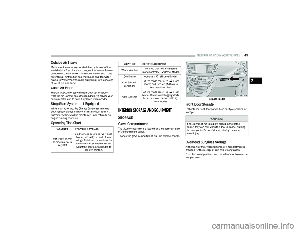
The glove compartment is located on the passenger side
of the instrument panel.
To open the glove compartment, pull the release handle.
Release Handle
Front Door Storage
Both interior front door panels have multiple pockets for
storage.
Overhead Sunglass Storage
At the front of the overhead console, a compartment is
provided for the storage of one pair of sunglasses.
From the closed position, push the indentation to open the
compartment.
WEATHER CONTROL SETTINGS
Hot Weather And
Vehicle Interior Is Very Hot Set the mode control to (Panel
Mode), (A/C) on, and blower
on high. Roll down the windows for a minute to flush out the hot air.
Adjust the controls as needed to achieve comfort.
Warm Weather Turn (A/C) on and set the
mode control to (Panel Mode).
Cool Sunny Operate in (Bi-Level Mode).
Cool & Humid Conditions Set the mode control to (Floor
Mode) and turn (A/C) on to keep windows clear.
Cold Weather Set the mode control to (Floor
Mode). If windshield fogging starts to occur, move the control to (Mix Mode).
WEATHER CONTROL SETTINGS
WARNING!
If containers of hot liquid are placed in the bottle
holder, they can spill when the door is closed, burning
the occupants. Be careful when closing the doors to
avoid injury.
2
23_RUV_OM_EN_US_t.book Page 49
Page 56 of 256
54GETTING TO KNOW YOUR VEHICLE
WINDOWS
POWER WINDOWS
The window switches on the driver’s door trim panel
control all of the door windows.
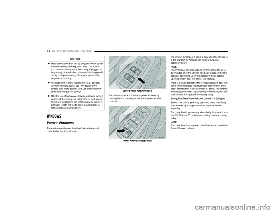
Driver’s Power Window Controls
The driver may lock out the rear power windows by
pushing the bar control just below the power window
controls.
Power Window Lockout Switch
The window switches will operate only when the ignition is
in the ON/RUN or ACC position and during power
accessory delay.
NOTE:Power Window controls will also remain active for up to
10 minutes after the ignition has been placed in the OFF
position, depending upon the accessory delay setting.
Opening a front door will cancel this feature.
There is a single control on the front passenger’s door trim
panel which operates the passenger door window and a
set of controls that lock and unlock all doors. The controls
will operate only when the ignition is in the ON/RUN or ACC
position and during power accessory delay.
Sliding Side Door Power Window Control — If Equipped
Second row passengers may open and close the sliding
door window by a single control on the door handle
assembly.
The controls will operate only when the ignition switch is in
the ON/RUN or ACC position and during power accessory
delay.
NOTE:The controls will not operate if the driver has activated the
Power Window Lockout.
CAUTION!
Many accessories that can be plugged in draw power
from the vehicle's battery, even when not in use
(i.e., cellular phones, etc.). Eventually, if plugged in
long enough, the vehicle's battery will discharge suffi -
ciently to degrade battery life and/or prevent the
engine from starting.
Accessories that draw higher power (i.e., coolers,
vacuum cleaners, lights, etc.) will degrade the
battery even more quickly. Only use these intermit -
tently and with greater caution.
After the use of high power draw accessories, or long
periods of the vehicle not being started (with acces -
sories still plugged in), the vehicle must be driven a
sufficient length of time to allow the generator to
recharge the vehicle's battery.
23_RUV_OM_EN_US_t.book Page 54
Page 58 of 256
56GETTING TO KNOW YOUR VEHICLE
HOOD
OPENING
The hood release lever (to open the primary latch) and
safety latch (to open the secondary latch) must be
released to open the hood.
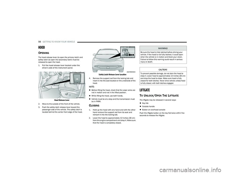
1. Pull the hood release lever located under the
driver’s side of the instrument panel.
Hood Release Lever
2. Move to the outside of the front of the vehicle.
3. Push the safety latch release lever toward the passenger side of the vehicle. The safety latch is
located behind the center front edge of the hood.
Safety Latch Release Lever Location
4. Remove the support rod from the locking tab and insert it into the seat located on the underside of the
hood.
NOTE:
Before lifting the hood, check that the wiper arms are
not in motion and not in the lifted position.
While lifting the hood, use both hands.
Vehicle must be at a stop and the transmission must
be in PARK.
CLOSING
1. Hold up the hood with one hand and with the other
hand remove the support rod from its seat and
reinsert it into the locking tab.
2. Lower the hood to approximately 12 inches (30 cm) from the engine compartment and drop it. Make sure
that the hood is completely closed.
LIFTGATE
TO UNLOCK/OPEN THE LIFTGATE
The liftgate may be released in several ways:
Key fob
Outside handle
Button on overhead console
Push the liftgate button on the key fob twice within five
seconds to release the liftgate.
WARNING!
Be sure the hood is fully latched before driving your
vehicle. If the hood is not fully latched, it could open
when the vehicle is in motion and block your vision.
Failure to follow this warning could result in serious
injury or death.
CAUTION!
To prevent possible damage, do not slam the hood to
close it. Lower hood to approximately 12 inches (30 cm)
and drop the hood to close. Make sure hood is fully
closed for both latches. Never drive vehicle unless hood
is fully closed, with both latches engaged.
23_RUV_OM_EN_US_t.book Page 56
Page 62 of 256
60GETTING TO KNOW YOUR INSTRUMENT PANEL
BASE INSTRUMENT CLUSTER
D
ESCRIPTIONS
Use this QR code to access your digital
experience.
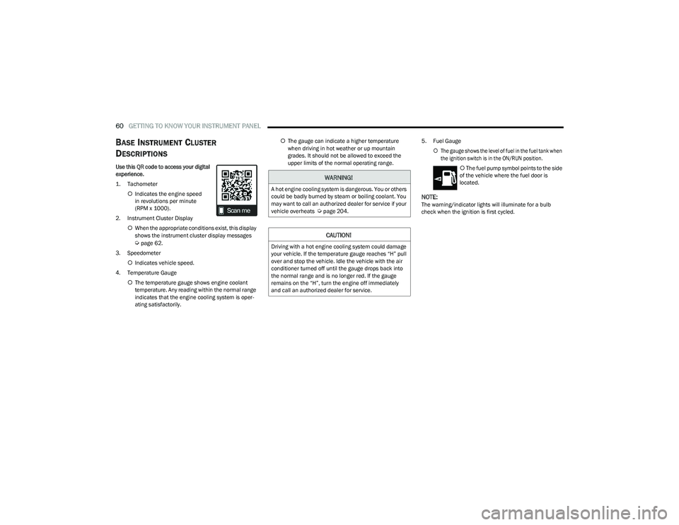
1. Tachometer
Indicates the engine speed
in revolutions per minute
(RPM x 1000).
2. Instrument Cluster Display When the appropriate conditions exist, this display
shows the instrument cluster display messages
Úpage 62.
3. Speedometer Indicates vehicle speed.
4. Temperature Gauge The temperature gauge shows engine coolant
temperature. Any reading within the normal range
indicates that the engine cooling system is oper -
ating satisfactorily.
The gauge can indicate a higher temperature
when driving in hot weather or up mountain
grades. It should not be allowed to exceed the
upper limits of the normal operating range. 5. Fuel Gauge
The gauge shows the level of fuel in the fuel tank when
the ignition switch is in the ON/RUN position.
The fuel pump symbol points to the side
of the vehicle where the fuel door is
located.
NOTE:The warning/indicator lights will illuminate for a bulb
check when the ignition is first cycled.
WARNING!
A hot engine cooling system is dangerous. You or others
could be badly burned by steam or boiling coolant. You
may want to call an authorized dealer for service if your
vehicle overheats
Úpage 204.
CAUTION!
Driving with a hot engine cooling system could damage
your vehicle. If the temperature gauge reaches “H” pull
over and stop the vehicle. Idle the vehicle with the air
conditioner turned off until the gauge drops back into
the normal range and is no longer red. If the gauge
remains on the “H”, turn the engine off immediately
and call an authorized dealer for service.
23_RUV_OM_EN_US_t.book Page 60
Page 64 of 256
62GETTING TO KNOW YOUR INSTRUMENT PANEL
PREMIUM INSTRUMENT CLUSTER
D
ESCRIPTIONS
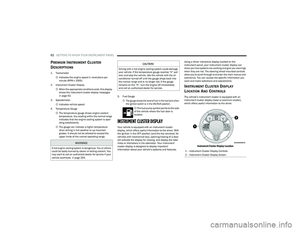
1. Tachometer
Indicates the engine speed in revolutions per
minute (RPM x 1000).
2. Instrument Cluster Display When the appropriate conditions exist, this display
shows the instrument cluster display messages
Úpage 62.
3. Speedometer Indicates vehicle speed.
4. Temperature Gauge The temperature gauge shows engine coolant
temperature. Any reading within the normal range
indicates that the engine cooling system is oper -
ating satisfactorily.
The gauge can indicate a higher temperature
when driving in hot weather or up mountain
grades. It should not be allowed to exceed the
upper limits of the normal operating range. 5. Fuel Gauge
The gauge shows the level of fuel in the fuel tank when
the ignition switch is in the ON/RUN position.
The fuel pump symbol points to the side
of the vehicle where the fuel door is
located.
INSTRUMENT CLUSTER DISPLAY
Your vehicle is equipped with an instrument cluster
display, which offers useful information to the driver. With
the ignition in the OFF position (and the key removed, for
vehicles with mechanical key), opening/closing of a door
will activate the display for viewing, and display the total
miles or kilometers in the odometer. Your instrument
cluster display is designed to display important
information about your vehicle’s systems and features. Using a driver interactive display located on the
instrument panel, your instrument cluster display can
show you how systems are working and give you warnings
when they are not. The steering wheel mounted controls
allow you to scroll through and enter the main menus and
submenus. You can access the specific information you
want and make selections and adjustments.
INSTRUMENT CLUSTER DISPLAY
L
OCATION AND CONTROLS
The vehicle’s instrument cluster is equipped with an
instrument cluster display (base or premium cluster),
which offers useful information to the driver.
Instrument Cluster Display Location
WARNING!
A hot engine cooling system is dangerous. You or others
could be badly burned by steam or boiling coolant. You
may want to call an authorized dealer for service if your
vehicle overheats
Úpage 204.
CAUTION!
Driving with a hot engine cooling system could damage
your vehicle. If the temperature gauge reaches “H” pull
over and stop the vehicle. Idle the vehicle with the air
conditioner turned off until the gauge drops back into
the normal range and is no longer red. If the gauge
remains on the “H”, turn the engine off immediately
and call an authorized dealer for service.
1 – Instrument Cluster Display Controls
2 – Instrument Cluster Display Screen
23_RUV_OM_EN_US_t.book Page 62
Page 65 of 256
GETTING TO KNOW YOUR INSTRUMENT PANEL63
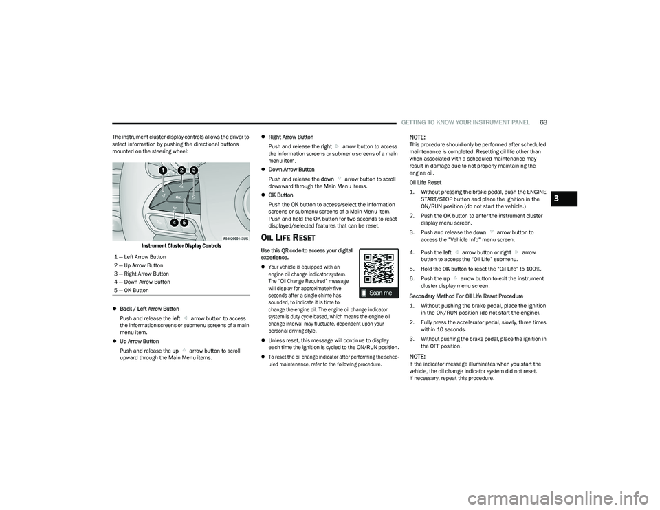
The instrument cluster display controls allows the driver to
select information by pushing the directional buttons
mounted on the steering wheel:
Instrument Cluster Display Controls
Back / Left Arrow Button
Push and release the left arrow button to access
the information screens or submenu screens of a main
menu item.
Up Arrow Button
Push and release the up arrow button to scroll
upward through the Main Menu items.
Right Arrow Button
Push and release the right arrow button to access
the information screens or submenu screens of a main
menu item.
Down Arrow Button
Push and release the down arrow button to scroll
downward through the Main Menu items.
OK Button
Push the OK button to access/select the information
screens or submenu screens of a Main Menu item.
Push and hold the OK button for two seconds to reset
displayed/selected features that can be reset.
OIL LIFE RESET
Use this QR code to access your digital
experience.
Your vehicle is equipped with an
engine oil change indicator system.
The “Oil Change Required” message
will display for approximately five
seconds after a single chime has
sounded, to indicate it is time to
change the engine oil. The engine oil change indicator
system is duty cycle based, which means the engine oil
change interval may fluctuate, dependent upon your
personal driving style.
Unless reset, this message will continue to display
each time the ignition is cycled to the ON/RUN position.
To reset the oil change indicator after performing the sched -
uled maintenance, refer to the following procedure.
NOTE:This procedure should only be performed after scheduled
maintenance is completed. Resetting oil life other than
when associated with a scheduled maintenance may
result in damage due to not properly maintaining the
engine oil.
Oil Life Reset
1. Without pressing the brake pedal, push the ENGINE START/STOP button and place the ignition in the
ON/RUN position (do not start the vehicle.)
2. Push the OK button to enter the instrument cluster
display menu screen.
3. Push and release the down arrow button to
access the ”Vehicle Info” menu screen.
4. Push the left arrow button or right arrow
button to access the “Oil Life” submenu.
5. Hold the OK button to reset the “Oil Life” to 100%.
6. Push the up arrow button to exit the instrument
cluster display menu screen.
Secondary Method For Oil Life Reset Procedure
1. Without pushing the brake pedal, place the ignition in the ON/RUN position (do not start the engine).
2. Fully press the accelerator pedal, slowly, three times within 10 seconds.
3. Without pushing the brake pedal, place the ignition in the OFF position.
NOTE:If the indicator message illuminates when you start the
vehicle, the oil change indicator system did not reset.
If necessary, repeat this procedure.
1 — Left Arrow Button
2 — Up Arrow Button
3 — Right Arrow Button
4 — Down Arrow Button
5 — OK Button
3
23_RUV_OM_EN_US_t.book Page 63