ESP CHRYSLER VOYAGER 2023 Owners Manual
[x] Cancel search | Manufacturer: CHRYSLER, Model Year: 2023, Model line: VOYAGER, Model: CHRYSLER VOYAGER 2023Pages: 256, PDF Size: 13.97 MB
Page 2 of 256

The driver’s primary responsibility is the safe operation of the vehicle. Driving while distracted can result in loss of vehicle control, resulting in an accident and personal
injury. FCA US LLC strongly recommends that the driver use extreme caution when using any device or feature that may take their attention off the road. Use of any
electrical devices, such as cellular telephones, computers, portable radios, vehicle navigation or other devices, by the driver while the vehicle is moving is dangerous
and could lead to a serious accident. Texting while driving is also dangerous and should never be done while the vehicle is moving. If you find yourself unable to devote
your full attention to vehicle operation, pull off the road to a safe location and stop your vehicle. Some states or provinces prohibit the use of cellular telephones or
texting while driving. It is always the driver’s responsibility to comply with all local laws.
This Owner’s Manual has been prepared to help you get acquainted with your new Chrysler brand vehicle and to provide a convenient reference source for common
questions.
Not all features shown in this manual may apply to your vehicle. For additional information, visit mopar.com/om (USA), owners.mopar.ca (Canada) or your local Chrysler
brand dealer.
U.S. Residents: If you are the first registered retail owner of your vehicle, you may obtain a complimentary printed copy of the Warranty Booklet by calling
1-800-247-9753 or by contacting your dealer. Replacement kits can be purchased by visiting www.techauthority.com.
Canadian Residents: If you are the first registered retail owner of your vehicle, you may obtain a complimentary printed copy of the Warranty Booklet or purchase a
replacement kit by calling 1-800-387-1143 or by contacting your dealer.
WARNING: Operating, servicing and maintaining a passenger vehicle or off-highway motor vehicle can
expose you to chemicals including engine exhaust, carbon monoxide, phthalates, and lead, which are known to
the State of California to cause cancer and birth defects or other reproductive harm. To minimize exposure,
avoid breathing exhaust, do not idle the engine except as necessary, service your vehicle in a well-ventilated area
and wear gloves or wash your hands frequently when servicing your vehicle. For more information go to
www.P65Warnings.ca.gov/passenger-vehicle.
This Owner’s Manual illustrates and describes the operation of features and equipment that are either standard or optional on this vehicle. This manual may also include
a description of features and equipment that are no longer available or were not ordered on this vehicle. Please disregard any features and equipment described in this
manual that are not on this vehicle. FCA US LLC reserves the right to make changes in design and specifications, and/or make additions to or improvements to its
products without imposing any obligation upon itself to install them on pr\
oducts previously manufactured.
With respect to any vehicles sold in Canada, the name FCA US LLC shall be deemed to be deleted and the name FCA Canada Inc. used in substitution therefore.
This Owner’s Manual is intended to familiarize you with the important features of your vehicle. Your most up-to-date Owner’s Manual, Radio Instruction Manual and
Warranty Booklet can be found by visiting the website on the back cover.
DRIVING AND ALCOHOL
Drunk driving is one of the most frequent causes of accidents. Your driving ability can be seriously impaired with blood alcohol levels far below the legal minimum. If
you are drinking, don’t drive. Ride with a designated non-drinking driver, call a cab, a rideshare, a friend, or use public transportation.
WARNING
Driving after drinking can lead to an accident. Your perceptions are less sharp, your reflexes are slower and your judgment is impaired when you have been drinking.
Never drink and then drive.
ROADSIDE ASSISTANCE 24 HOURS, 7 DAYS A WEEK AT YOUR SERVICE. CALL 1-800-521-2779 OR VISIT CHRYSLER.RSAHELP.COM (USA) CALL 1-800-363-4869 OR VISIT FCA.ROADSIDEAID.COM (CANADA) SERVICES: Flat Tire Service, Out Of Gas/ Fuel Delivery, Battery Jump Assistance, Lockout Service and Towing Service
Please see the Customer Assistance chapter in this Owner’s Manual for further information.
FCA US LLC reserves the right to modify the terms or discontinue the Roadside Assistance Program at any time. The Roadside Assistance Program is subject to restrictions and conditions of use, that are determined solely by FCA US LLC.
Page 6 of 256
4
MULTIMEDIA
UCONNECT SYSTEMS ..................................................... 104
CYBERSECURITY ............................................................. 104
UCONNECT SETTINGS...................................................... 105
Customer Programmable Features ........................ 105
RADIO OPERATION AND MOBILE PHONES .................. 120 Regulatory And Safety Information .......................... 120
SAFETY
SAFETY FEATURES........................................................... 121Anti-Lock Brake System (ABS) ................................. 121Rear Seat Reminder Alert (RSRA) ............................ 121
Electronic Brake Control (EBC) System .................. 122
AUXILIARY DRIVING SYSTEMS ...................................... 126 Blind Spot Monitoring (BSM) — If Equipped ............ 126Forward Collision Warning (FCW) With
Mitigation — If Equipped ........................................... 129
Tire Pressure Monitoring
System (TPMS) .......................................................... 131
OCCUPANT RESTRAINT SYSTEMS ................................ 134 Occupant Restraint Systems Features ................... 134Important Safety Precautions .................................. 134Seat Belt Systems .................................................... 135
Supplemental Restraint Systems (SRS) .................. 143Child Restraints ......................................................... 153 SAFETY TIPS .................................................................... 167
Transporting Passengers ......................................... 167
Transporting Pets .................................................... 167
Connected Vehicles .................................................. 167Safety Checks You Should Make Inside
The Vehicle ............................................................... 167Periodic Safety Checks You Should Make
Outside The Vehicle .................................................. 168Exhaust Gas ............................................................. 169
Carbon Monoxide Warnings ..................................... 169IN CASE OF EMERGENCY
HAZARD WARNING FLASHERS ..................................... 170
SOS AND ASSIST MIRROR — IF EQUIPPED ................. 170
JACKING AND TIRE CHANGING —
IF EQUIPPED .................................................................... 173 Preparations For Jacking ......................................... 173
Jack And Spare Tire Location................................... 174Equipment Removal ................................................ 174
Jacking Instructions.................................................. 175Road Tire Installation ............................................... 178
Portable Air Compressor — If Equipped .................. 179
Return Inflatable Spare Tire..................................... 180
TIRE SERVICE KIT — IF EQUIPPED ................................. 180
JUMP STARTING............................................................... 185 Preparations For Jump Start .................................... 185Jump Starting Procedure.......................................... 186 REFUELING IN EMERGENCY – IF EQUIPPED ...............187
IF YOUR ENGINE OVERHEATS......................................... 187
MANUAL PARK RELEASE ...............................................188
FREEING A STUCK VEHICLE ........................................... 189
TOWING A DISABLED VEHICLE.......................................190
ENHANCED ACCIDENT RESPONSE
SYSTEM (EARS) ...............................................................191
EVENT DATA RECORDER (EDR)......................................191
SERVICING AND MAINTENANCE
SCHEDULED SERVICING ................................................. 192 Maintenance Plan ..................................................... 193
ENGINE COMPARTMENT ................................................. 195 3.6L Engine................................................................ 195
Checking Oil Level ..................................................... 196Adding Washer Fluid ................................................ 196
Maintenance-Free Battery ........................................ 196Pressure Washing ..................................................... 197
VEHICLE MAINTENANCE ................................................. 197 Engine Oil .................................................................. 197
Engine Oil Filter ......................................................... 197
Engine Air Cleaner Filter .......................................... 198
Accessory Drive Belt Inspection ............................... 198Air Conditioner Maintenance .................................... 199
Body Lubrication........................................................ 200
Windshield Wiper Blades .......................................... 201
23_RUV_OM_EN_US_t.book Page 4
Page 20 of 256
18GETTING TO KNOW YOUR VEHICLE
KEYLESS ENTER ‘N GO™ —
P
ASSIVE ENTRY
The Passive Entry system is an enhancement to the
vehicle’s Remote Keyless Entry system and a feature of
Keyless Enter ‘n Go™ — Passive Entry. This feature allows
you to lock and unlock the vehicle’s door(s) without having
to push the key fob lock or unlock buttons.
NOTE:
Passive Entry may be programmed on/off through the
Uconnect system Úpage 105.
The key fob may not be detected by the vehicle Passive
Entry system if it is located next to a mobile phone,
laptop, or other electronic device; these devices may
block the key fob’s wireless signal and prevent the
Passive Entry handle from locking/unlocking the
vehicle.
If set by the customer in the Uconnect Settings,
unlocking with Passive Entry will initiate illuminated
approach (low beams, license plate lamp, position
lamps) for the duration of 0, 30, 60 or 90 seconds.
Passive Entry also initiates two flashes of the turn
signals.
If wearing gloves, if it has been raining/snowing, or
there is salt/dirt covering the Passive Entry door
handle, the unlock sensitivity can be affected, resulting
in a slower response time.
The doors may unlock when water is sprayed on the
Passive Entry door handles, if the key fob is located
outside of the vehicle within 5 ft (1.5 m) of the handle.
If the vehicle is unlocked by Passive Entry and no door
is opened within 60 seconds, the vehicle will relock and
will arm the security system (if equipped).
The sliding side doors can be unlocked from the
outside using the Passive Entry system.
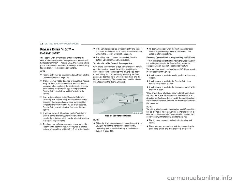
To Unlock From The Driver Or Passenger Side:
With a valid key fob within 5 ft (1.5 m) of the door handle,
grab the handle to unlock the vehicle. Grabbing the
driver’s door handle will unlock the driver’s side doors
(driver/sliding door) automatically. Grabbing the front
passenger door handle to unlock all four doors and the
liftgate automatically. The interior door panel lock knob
will rotate when the door is unlocked.
Grab The Door Handle To Unlock
NOTE:
Either the driver door only or all doors will unlock when
you grab hold of the front driver’s door handle,
depending on the selected setting in the Uconnect
system
Úpage 105.
All doors will unlock when the front passenger door
handle is grabbed regardless of the driver’s door
unlock preference setting.
Frequency Operated Button Integrated Key (FOBIK-Safe)
To minimize the possibility of unintentionally locking a key
fob inside your vehicle, the Passive Entry system is
equipped with an automatic door unlock feature.
There are three situations that trigger a FOBIK-Safe search
in any Passive Entry vehicle:
A lock request is made by a valid key fob while a door
is open.
A lock request is made by the Passive Entry door
handle while a door is open.
A lock request is made by the door panel switch while
the door is open.
When any of these situations occur, after all open doors
are shut, the FOBIK-Safe search will be executed. If it
detects a key fob inside the car, and it does not detect any
key fob outside the car, then the car will unlock and alert
the customer.
NOTE:
The vehicle will only unlock the doors when a valid Passive Entry
key fob is detected inside the vehicle, and no valid key fob is
detected outside the vehicle. The vehicle will not unlock the
doors when any of the following conditions are met:
The doors are manually locked using the door lock
knobs.
Three attempts are made to lock the doors using the
door panel switch and then the doors are closed.
23_RUV_OM_EN_US_t.book Page 18
Page 25 of 256
GETTING TO KNOW YOUR VEHICLE23
SEATS
Seats are a part of the Occupant Restraint system of the
vehicle.
MANUAL ADJUSTMENT
(F
RONT SEATS) — IF EQUIPPED
Manual Front Adjuster
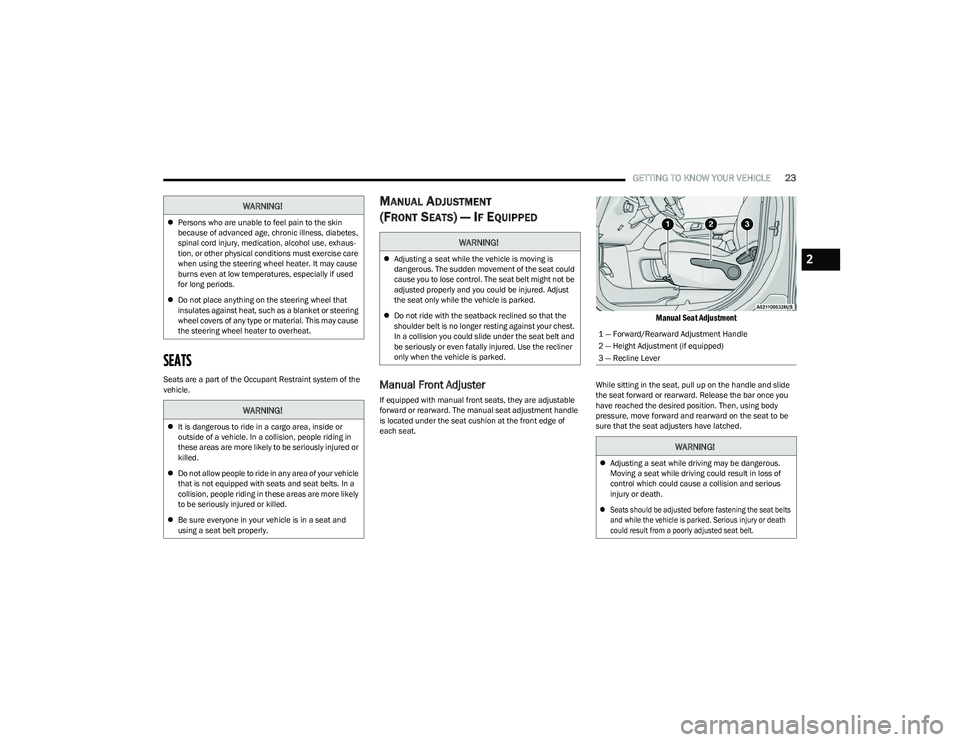
If equipped with manual front seats, they are adjustable
forward or rearward. The manual seat adjustment handle
is located under the seat cushion at the front edge of
each seat.
Manual Seat Adjustment
While sitting in the seat, pull up on the handle and slide
the seat forward or rearward. Release the bar once you
have reached the desired position. Then, using body
pressure, move forward and rearward on the seat to be
sure that the seat adjusters have latched.
WARNING!
Persons who are unable to feel pain to the skin
because of advanced age, chronic illness, diabetes,
spinal cord injury, medication, alcohol use, exhaus -
tion, or other physical conditions must exercise care
when using the steering wheel heater. It may cause
burns even at low temperatures, especially if used
for long periods.
Do not place anything on the steering wheel that
insulates against heat, such as a blanket or steering
wheel covers of any type or material. This may cause
the steering wheel heater to overheat.
WARNING!
It is dangerous to ride in a cargo area, inside or
outside of a vehicle. In a collision, people riding in
these areas are more likely to be seriously injured or
killed.
Do not allow people to ride in any area of your vehicle
that is not equipped with seats and seat belts. In a
collision, people riding in these areas are more likely
to be seriously injured or killed.
Be sure everyone in your vehicle is in a seat and
using a seat belt properly.
WARNING!
Adjusting a seat while the vehicle is moving is
dangerous. The sudden movement of the seat could
cause you to lose control. The seat belt might not be
adjusted properly and you could be injured. Adjust
the seat only while the vehicle is parked.
Do not ride with the seatback reclined so that the
shoulder belt is no longer resting against your chest.
In a collision you could slide under the seat belt and
be seriously or even fatally injured. Use the recliner
only when the vehicle is parked.
1 — Forward/Rearward Adjustment Handle
2 — Height Adjustment (if equipped)
3 — Recline Lever
WARNING!
Adjusting a seat while driving may be dangerous.
Moving a seat while driving could result in loss of
control which could cause a collision and serious
injury or death.
Seats should be adjusted before fastening the seat belts
and while the vehicle is parked. Serious injury or death
could result from a poorly adjusted seat belt.
2
23_RUV_OM_EN_US_t.book Page 23
Page 36 of 256

34GETTING TO KNOW YOUR VEHICLE
Tilting The Seat Up Or Down
The angle of the seat cushion can be adjusted in two
directions. Pull upward or push downward on the front of
the seat switch, the front of the seat cushion will move in
the direction of the switch. Release the switch when the
desired position has been reached.
Reclining The Seatback
The angle of the seatback can be adjusted forward or
rearward. Push the seatback switch forward or rearward,
the seat will move in the direction of the switch. Release
the switch when the desired position is reached.
Power Lumbar — If Equipped
Power Lumbar Switch Location
The front driver’s seat may be equipped with a four-way
lumbar adjustment. The power lumbar switch is located on
the outboard side of the equipped power seat. Push the
switch forward or rearward to increase or decrease the
lumbar support. Push the switch upward or downward to
raise or lower the lumbar support.
HEATED SEATS
Front Heated Seats — If Equipped
The front heated seats control buttons are
located in the touchscreen.
You can choose from HI, LO or off heat settings.
The indicator lights in each switch indicate the level of
heat in use. Two indicator lights will illuminate for HI, one
for LO and none for off.
Press the heated seat button once to turn the HI setting on.
Press the heated seat button a second time to turn the
LO setting on.
Press the heated seat button a third time to turn the
heating elements off.
The level of heat selected will stay on until the operator
changes it.
NOTE:
Once a heat setting is selected, heat will be felt within
two to five minutes.
The engine must be running for the heated seats to
operate.
For information on use with the Remote Start system, see
Úpage 15.
WARNING!
Adjusting a seat while driving may be dangerous.
Moving a seat while driving could result in loss of
control which could cause a collision and serious
injury or death.
Seats should be adjusted before fastening the seat belts
and while the vehicle is parked. Serious injury or death
could result from a poorly adjusted seat belt.
Do not ride with the seatback reclined so that the
shoulder belt is no longer resting against your chest.
In a collision you could slide under the seat belt,
which could result in serious injury or death.
CAUTION!
Do not place any article under a power seat or impede
its ability to move as it may cause damage to the seat
controls. Seat travel may become limited if movement
is stopped by an obstruction in the seat's path.
WARNING!
Persons who are unable to feel pain to the skin
because of advanced age, chronic illness, diabetes,
spinal cord injury, medication, alcohol use, exhaus -
tion or other physical condition must exercise care
when using the seat heater. It may cause burns even
at low temperatures, especially if used for long
periods of time.
Do not place anything on the seat or seatback that
insulates against heat, such as a blanket or cushion.
This may cause the seat heater to overheat. Sitting in
a seat that has been overheated could cause serious
burns due to the increased surface temperature of
the seat.
23_RUV_OM_EN_US_t.book Page 34
Page 67 of 256
GETTING TO KNOW YOUR INSTRUMENT PANEL65
Oil Pressure
Displays the actual oil pressure.
Oil Life
Displays the remaining engine oil life as a percentage.
To reset the Oil Life, you must hold the OK button.
The “Hold OK to Reset” instruction will be displayed at all
times, but the following conditions will need to be met in
order to reset Oil Life:
The ignition must be in the ON/RUN position
If the conditions are met, holding the OK button will reset
the gauge and the numeric display will return to 100%.
If the conditions are not met, a pop-up message will
display for five seconds, describing the required
conditions, and then the Oil Life screen will reappear.
Battery Voltage
Displays the actual battery voltage.
Engine Hours — If Equipped
Displays the number of hours of engine operation.
Driver Assist — If Equipped
Push and release the up or down arrow button
until the Driver Assist display icon is highlighted in the
instrument cluster display
Úpage 86.
Fuel Economy
Push and release the up or down arrow button
until the Fuel Economy Menu item is highlighted in the
instrument cluster display. The Fuel Economy Menu will
display the following:
Two submenu pages that can be toggled between
using the left and right arrow buttons; one
with Current Value displayed and one without the
Current Value displayed:
Average Fuel Economy (MPG, L/100 km, or km/L)
Range To Empty (miles or km)
Current Fuel Economy (MPG, L/100 km, or km/L)
The Max and Min values will correspond to the
particular engine requirements
Hold OK to reset average fuel eco nomy information.
Trip Info
Push and release the up or down arrow button
until the Trip Menu item is highlighted in the instrument
cluster display. Push the left or right arrow button
to scroll through the Trip A and Trip B submenus. The Trip
information will display the following:
Distance
Average Fuel Economy
Elapsed Time
Hold the OK button to reset feature information.
Stop / Start – If Equipped
Push and release the up or down arrow button
until the Stop/Start menu title is displayed in the
instrument cluster display.
Audio
Push and release the up or down arrow button
until the Audio Menu displays in the instrument cluster
display.
Messages
Push and release the up or down arrow button
until Messages is highlighted in the instrument cluster
display. This feature shows the number of stored warning
messages. Pushing the right arrow button will allow
you to see what the stored messages are.
NOTE:The pop-up messages indicate the status of the system
and/or the conditions that need to be met. Messages
remain in the stored stack until condition is cleared.
Screen Setup
Push and release the up or down arrow button
until the Screen Setup Menu displays in the instrument
cluster display. Push and release the OK button to enter
the submenus. The Screen Setup feature allows you to
change what information is displayed in the instrument
cluster as well as the location that information is
displayed.
NOTE:Based on your vehicles trim level, some of the following
options may not be available.
3
23_RUV_OM_EN_US_t.book Page 65
Page 73 of 256
GETTING TO KNOW YOUR INSTRUMENT PANEL71
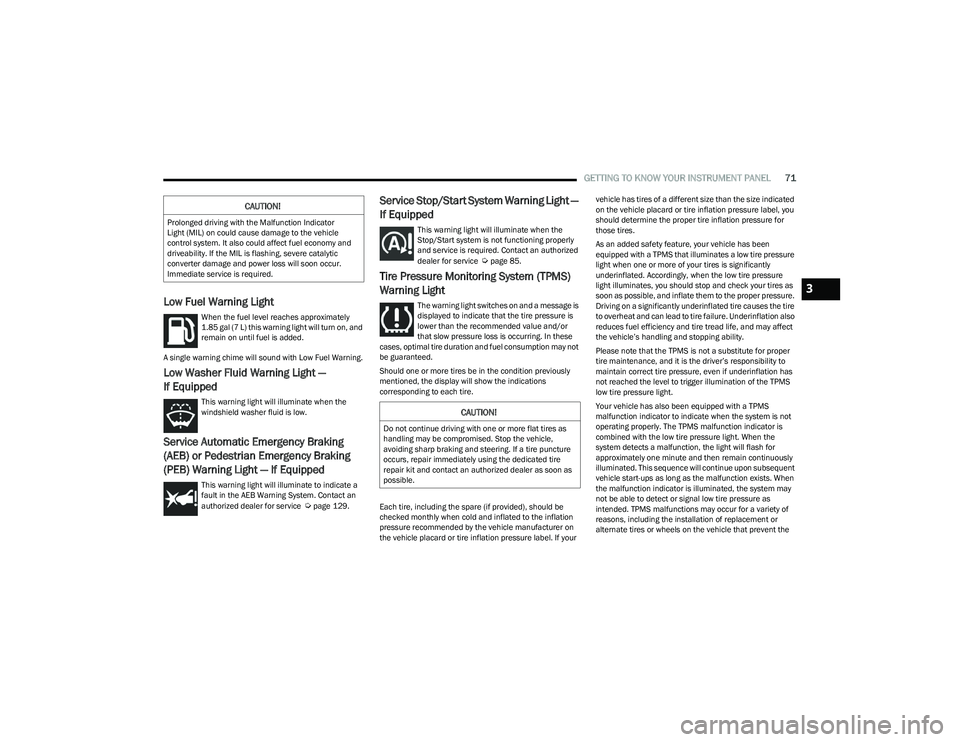
Low Fuel Warning Light
When the fuel level reaches approximately
1.85 gal (7 L) this warning light will turn on, and
remain on until fuel is added.
A single warning chime will sound with Low Fuel Warning.
Low Washer Fluid Warning Light —
If Equipped
This warning light will illuminate when the
windshield washer fluid is low.
Service Automatic Emergency Braking
(AEB) or Pedestrian Emergency Braking
(PEB) Warning Light — If Equipped
This warning light will illuminate to indicate a
fault in the AEB Warning System. Contact an
authorized dealer for service
Úpage 129.
Service Stop/Start System Warning Light —
If Equipped
This warning light will illuminate when the
Stop/Start system is not functioning properly
and service is required. Contact an authorized
dealer for service
Úpage 85.
Tire Pressure Monitoring System (TPMS)
Warning Light
The warning light switches on and a message is
displayed to indicate that the tire pressure is
lower than the recommended value and/or
that slow pressure loss is occurring. In these
cases, optimal tire duration and fuel consumption may not
be guaranteed.
Should one or more tires be in the condition previously
mentioned, the display will show the indications
corresponding to each tire.
Each tire, including the spare (if provided), should be
checked monthly when cold and inflated to the inflation
pressure recommended by the vehicle manufacturer on
the vehicle placard or tire inflation pressure label. If your vehicle has tires of a different size than the size indicated
on the vehicle placard or tire inflation pressure label, you
should determine the proper tire inflation pressure for
those tires.
As an added safety feature, your vehicle has been
equipped with a TPMS that illuminates a low tire pressure
light when one or more of your tires is significantly
underinflated. Accordingly, when the low tire pressure
light illuminates, you should stop and check your tires as
soon as possible, and inflate them to the proper pressure.
Driving on a significantly underinflated tire causes the tire
to overheat and can lead to tire failure. Underinflation also
reduces fuel efficiency and tire tread life, and may affect
the vehicle’s handling and stopping ability.
Please note that the TPMS is not a substitute for proper
tire maintenance, and it is the driver’s responsibility to
maintain correct tire pressure, even if underinflation has
not reached the level to trigger illumination of the TPMS
low tire pressure light.
Your vehicle has also been equipped with a TPMS
malfunction indicator to indicate when the system is not
operating properly. The TPMS malfunction indicator is
combined with the low tire pressure light. When the
system detects a malfunction, the light will flash for
approximately one minute and then remain continuously
illuminated. This sequence will continue upon subsequent
vehicle start-ups as long as the malfunction exists. When
the malfunction indicator is illuminated, the system may
not be able to detect or signal low tire pressure as
intended. TPMS malfunctions may occur for a variety of
reasons, including the installation of replacement or
alternate tires or wheels on the vehicle that prevent the
CAUTION!
Prolonged driving with the Malfunction Indicator
Light (MIL) on could cause damage to the vehicle
control system. It also could affect fuel economy and
driveability. If the MIL is flashing, severe catalytic
converter damage and power loss will soon occur.
Immediate service is required.
CAUTION!
Do not continue driving with one or more flat tires as
handling may be compromised. Stop the vehicle,
avoiding sharp braking and steering. If a tire puncture
occurs, repair immediately using the dedicated tire
repair kit and contact an authorized dealer as soon as
possible.
3
23_RUV_OM_EN_US_t.book Page 71
Page 74 of 256

72GETTING TO KNOW YOUR INSTRUMENT PANEL
TPMS from functioning properly. Always check the TPMS
malfunction light after replacing one or more tires or
wheels on your vehicle to ensure that the replacement or
alternate tires and wheels allow the TPMS to continue to
function properly.
YELLOW INDICATOR LIGHTS
Automatic Emergency Braking (AEB) or
Pedestrian Emergency Braking (PEB) OFF
Indicator Light — If Equipped
This indicator light illuminates to indicate that
Forward Collision Warning is off.
GREEN INDICATOR LIGHTS
Cruise Control Set Indicator Light —
If Equipped
This indicator light will illuminate when the
cruise control is set to the desired speed
Úpage 86.
Front Fog Indicator Light — If Equipped
This indicator light will illuminate when the
front fog lights are on.
KeySense Indicator Light — If Equipped
The KeySense indicator is illuminated when a
KeySense key is detected upon startup of the
vehicle. The indicator will remain lit for the
entire key cycle as a reminder that the
KeySense key is in use. While the KeySense key is in use,
the vehicle will respond to settings associated with the
KeySense profile
Úpage 10.
Parking/Headlights On Indicator Light
This indicator light will illuminate when the
parking lights or headlights are turned on.
Stop/Start Active Indicator Light —
If Equipped
This indicator light will illuminate when the
Stop/Start function is in “Autostop” mode
Úpage 85.
Turn Signal Indicator Lights
When the left or right turn signal is activated,
the turn signal indicator will flash
independently and the corresponding exterior
turn signal lamps will flash. Turn signals can be
activated when the multifunction lever is moved down
(left) or up (right).
NOTE:
A continuous chime will sound if the vehicle is driven
more than 1 mile (1.6 km) with either turn signal on.
Check for an inoperative outside light bulb if either indi -
cator flashes at a rapid rate.
WHITE INDICATOR LIGHTS
Cruise Control Ready Indicator Light
This indicator light will illuminate when the
cruise control is ready, but not set Úpage 86.
Set Speed Display Indicator Light
The Set Speed Display indicator light indicates
the set speed for the Cruise Control.
CAUTION!
The TPMS has been optimized for the original equip -
ment tires and wheels. TPMS pressures and warning
have been established for the tire size equipped on
your vehicle. Undesirable system operation or sensor
damage may result when using replacement equipment
that is not of the same size, type, and/or style. After -
market wheels can cause sensor damage. Using after -
market tire sealants may cause the Tire Pressure
Monitoring System (TPMS) sensor to become inopera -
ble. After using an aftermarket tire sealant it is recom -
mended that you take your vehicle to an authorized
dealer to have your sensor function checked.
23_RUV_OM_EN_US_t.book Page 72
Page 84 of 256
82STARTING AND OPERATING
BRAKE/TRANSMISSION SHIFT
I
NTERLOCK (BTSI) SYSTEM
This vehicle is equipped with a BTSI that holds the
transmission gear selector in PARK unless the brakes are
applied. To shift the transmission out of PARK, the engine
must be running and the brake pedal must be pressed.
The brake pedal must also be pressed to shift from
NEUTRAL into DRIVE or REVERSE when the vehicle is
stopped or moving at low speeds.
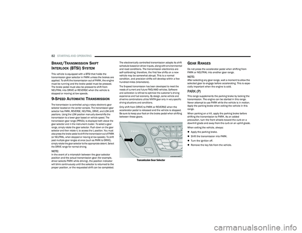
9-SPEED AUTOMATIC TRANSMISSION
The transmission is controlled using a rotary electronic gear
selector located on the center console. The transmission gear
selector has PARK, REVERSE, NEUTRAL, DRIVE, and LOW shift
positions. Using the LOW position manually downshifts the
transmission to a lower gear based on vehicle speed. The
transmission gear range (PRNDL) is displayed both above the
gear selector and in the instrument cluster. To select a gear
range, simply rotate the gear selector. Push down on the gear
selector and then rotate it, to access the L position. You must
also press the brake pedal to shift the transmission out of PARK
(or NEUTRAL, when stopped or moving at low speeds). To shift
past multiple gear ranges at once (such as PARK to DRIVE),
simply rotate the gear selector to the appropriate detent. Select
the DRIVE range for normal driving.
NOTE:In the event of a mismatch between the gear selector
position and the actual transmission gear (for example,
driver selects PARK while driving), the position indicator
will blink continuously until the selector is returned to the
proper position, or the requested shift can be completed. The electronically controlled transmission adapts its shift
schedule based on driver inputs, along with environmental
and road conditions. The transmission electronics are
self-calibrating; therefore, the first few shifts on a new
vehicle may be somewhat abrupt. This is a normal
condition, and precision shifts will develop within a few
hundred miles (kilometers).
The 9-speed transmission has been developed to meet the
needs of current and future FWD/AWD vehicles. Software
and calibration is refined to optimize the customer’s driving
experience and fuel economy. By design, some vehicle and
driveline combinations utilize NINTH gear only in very specific
driving situations and conditions.
Only shift from DRIVE to PARK or REVERSE when the
accelerator pedal is released and the vehicle is stopped.
Be sure to keep your foot on the brake pedal when shifting
between these gears.
Transmission Gear Selector
GEAR RANGES
Do not press the accelerator pedal when shifting from
PARK or NEUTRAL into another gear range.
NOTE:After selecting any gear range, wait a moment to allow the
selected gear to engage before accelerating. This is espe
-
cially important when the engine is cold.
PARK (P)
This range supplements the parking brake by locking the
transmission. The engine can be started in this range.
Never attempt to use PARK while the vehicle is in motion.
Apply the parking brake when exiting the vehicle in this
range.
When parking on a hill, apply the parking brake before
shifting the transmission to PARK. As an added
precaution, turn the front wheels toward the curb on a
downhill grade and away from the curb on an uphill grade.
When exiting the vehicle, always:
Apply the parking brake.
Shift the transmission into PARK.
Turn the ignition off.
Remove the key fob from the vehicle.
23_RUV_OM_EN_US_t.book Page 82
Page 85 of 256
STARTING AND OPERATING83
The following indicators should be used to ensure that you
have properly engaged the transmission into the PARK
position:
Look at the transmission gear position display and
verify that it indicates the PARK position (P), and is not
blinking.
With the brake pedal released, verify that the gear
selector will not move out of PARK.
REVERSE (R)
This range is for moving the vehicle backward. Shift into
REVERSE only after the vehicle has come to a complete stop.
NEUTRAL (N)
Use this range when the vehicle is standing for prolonged
periods with the engine running. The engine may be
started in this range. Apply the parking brake and shift the
transmission into PARK if you must exit the vehicle.
DRIVE (D)
This range should be used for most city and highway driving. It
provides the smoothest upshifts and downshifts, and the best
fuel economy. The transmission automatically upshifts through
all forward gears. The DRIVE position provides optimum driving
characteristics under all normal operating conditions.
If the transmission temperature exceeds normal operating
limits, the transmission controller may modify the transmission
shift schedule, reduce engine torque, and/or expand the range
of torque converter clutch engagement. This is done to prevent
transmission damage due to overheating.
If the transmission becomes extremely hot, the
Transmission Temperature Warning Light will illuminate, a
warning message will appear in the instrument cluster,
and the transmission may operate differently until the
transmission cools down.
During cold temperatures, transmission operation may be
modified depending on engine and transmission temperature
as well as vehicle speed. This feature improves warm-up time
of the engine and transmission to achieve maximum efficiency.
Engagement of the torque converter clutch, and shifts into
EIGHTH or NINTH gear, are inhibited until the transmission fluid
is warm
Ú
page 84. Normal operation will resume once the
transmission temperature has risen to a suitable level.
LOW (L)
Use this range for engine braking when descending
very steep grades. In this range, the transmission will
downshift for increased engine braking. To access the
LOW position, push down on the gear selector and rotate
it fully clockwise.
Transmission Limp Home Mode
Transmission function is monitored electronically for
abnormal conditions. If a condition is detected that could
result in transmission damage, Transmission Limp Home
Mode is activated. In this mode, the transmission may
operate only in a fixed gear, or may remain in NEUTRAL.
The Malfunction Indicator Light (MIL) may be illuminated.
Limp Home Mode may allow the vehicle to be driven to an
authorized dealer for service without damaging the
transmission.
CAUTION!
Before moving the transmission gear selector out of
PARK, you must start the engine, and also press the
brake pedal. Otherwise, damage to the gear selector
could result.
DO NOT race the engine when shifting from PARK
or NEUTRAL into another gear range, as this can
damage the drivetrain.
WARNING!
Do not coast in NEUTRAL and never turn off the ignition to
coast down a hill. These are unsafe practices that limit your
response to changing traffic or road conditions. You might
lose control of the vehicle and have a collision.
CAUTION!
Towing the vehicle, coasting, or driving for any other
reason with the transmission in NEUTRAL can cause
severe transmission damage.
If Recreational Towing
Úpage 101.
If Towing A Disabled Vehicle
Úpage 190.
4
23_RUV_OM_EN_US_t.book Page 83