buttons CHRYSLER VOYAGER 2023 Owners Manual
[x] Cancel search | Manufacturer: CHRYSLER, Model Year: 2023, Model line: VOYAGER, Model: CHRYSLER VOYAGER 2023Pages: 256, PDF Size: 13.97 MB
Page 20 of 256
18GETTING TO KNOW YOUR VEHICLE
KEYLESS ENTER ‘N GO™ —
P
ASSIVE ENTRY
The Passive Entry system is an enhancement to the
vehicle’s Remote Keyless Entry system and a feature of
Keyless Enter ‘n Go™ — Passive Entry. This feature allows
you to lock and unlock the vehicle’s door(s) without having
to push the key fob lock or unlock buttons.
NOTE:
Passive Entry may be programmed on/off through the
Uconnect system Úpage 105.
The key fob may not be detected by the vehicle Passive
Entry system if it is located next to a mobile phone,
laptop, or other electronic device; these devices may
block the key fob’s wireless signal and prevent the
Passive Entry handle from locking/unlocking the
vehicle.
If set by the customer in the Uconnect Settings,
unlocking with Passive Entry will initiate illuminated
approach (low beams, license plate lamp, position
lamps) for the duration of 0, 30, 60 or 90 seconds.
Passive Entry also initiates two flashes of the turn
signals.
If wearing gloves, if it has been raining/snowing, or
there is salt/dirt covering the Passive Entry door
handle, the unlock sensitivity can be affected, resulting
in a slower response time.
The doors may unlock when water is sprayed on the
Passive Entry door handles, if the key fob is located
outside of the vehicle within 5 ft (1.5 m) of the handle.
If the vehicle is unlocked by Passive Entry and no door
is opened within 60 seconds, the vehicle will relock and
will arm the security system (if equipped).
The sliding side doors can be unlocked from the
outside using the Passive Entry system.
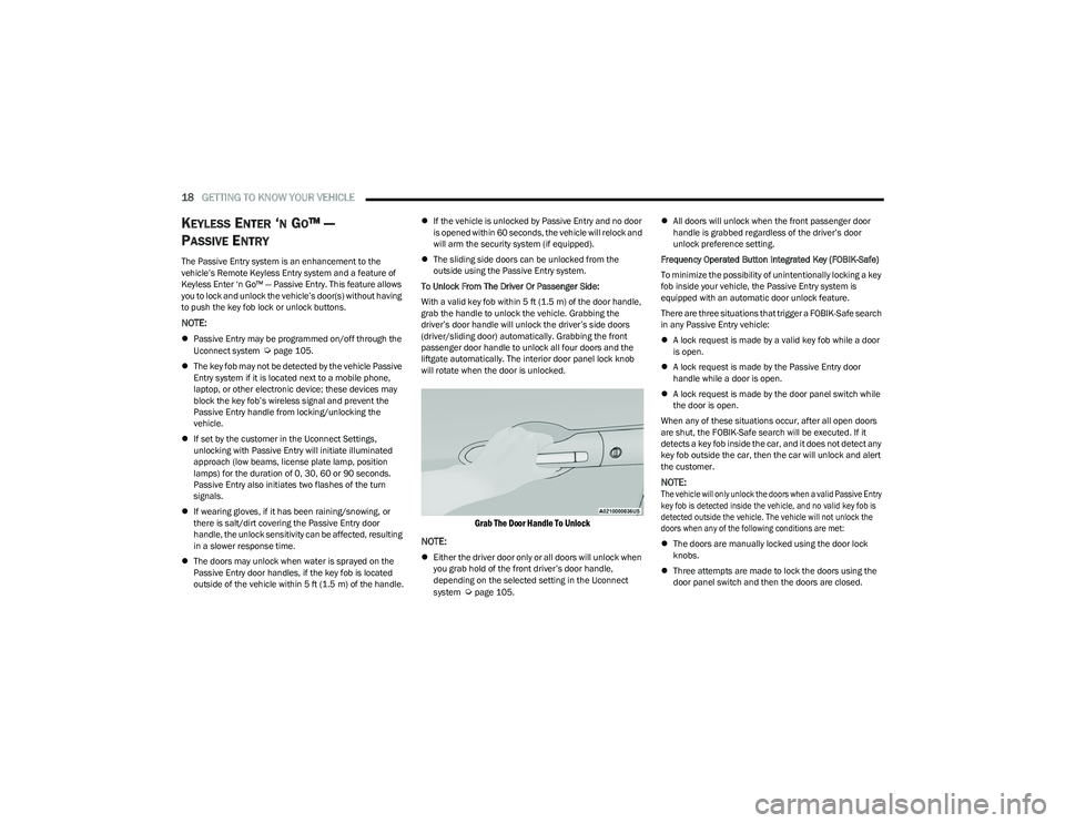
To Unlock From The Driver Or Passenger Side:
With a valid key fob within 5 ft (1.5 m) of the door handle,
grab the handle to unlock the vehicle. Grabbing the
driver’s door handle will unlock the driver’s side doors
(driver/sliding door) automatically. Grabbing the front
passenger door handle to unlock all four doors and the
liftgate automatically. The interior door panel lock knob
will rotate when the door is unlocked.
Grab The Door Handle To Unlock
NOTE:
Either the driver door only or all doors will unlock when
you grab hold of the front driver’s door handle,
depending on the selected setting in the Uconnect
system
Úpage 105.
All doors will unlock when the front passenger door
handle is grabbed regardless of the driver’s door
unlock preference setting.
Frequency Operated Button Integrated Key (FOBIK-Safe)
To minimize the possibility of unintentionally locking a key
fob inside your vehicle, the Passive Entry system is
equipped with an automatic door unlock feature.
There are three situations that trigger a FOBIK-Safe search
in any Passive Entry vehicle:
A lock request is made by a valid key fob while a door
is open.
A lock request is made by the Passive Entry door
handle while a door is open.
A lock request is made by the door panel switch while
the door is open.
When any of these situations occur, after all open doors
are shut, the FOBIK-Safe search will be executed. If it
detects a key fob inside the car, and it does not detect any
key fob outside the car, then the car will unlock and alert
the customer.
NOTE:
The vehicle will only unlock the doors when a valid Passive Entry
key fob is detected inside the vehicle, and no valid key fob is
detected outside the vehicle. The vehicle will not unlock the
doors when any of the following conditions are met:
The doors are manually locked using the door lock
knobs.
Three attempts are made to lock the doors using the
door panel switch and then the doors are closed.
23_RUV_OM_EN_US_t.book Page 18
Page 22 of 256
20GETTING TO KNOW YOUR VEHICLE
MANUAL SLIDING SIDE DOOR
The sliding door may be opened from the inside or the
outside. Pull outward on the exterior handle to open the
sliding door. The sliding door inside handle functions by
rocking forward and back. Rocking the handle backwards
opens the door and rocking forward releases the hold
open latch in order to close the door.
NOTE:If equipped with power sliding doors, using the manual
door handle will activate the power opening/closing
function. Allow the door to open or close fully on its own,
without forcing it.
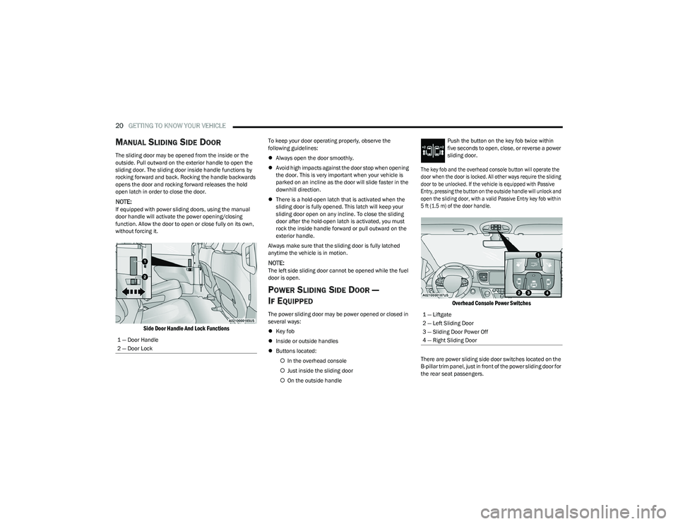
Side Door Handle And Lock Functions
To keep your door operating properly, observe the
following guidelines:
Always open the door smoothly.
Avoid high impacts against the door stop when opening
the door. This is very important when your vehicle is
parked on an incline as the door will slide faster in the
downhill direction.
There is a hold-open latch that is activated when the
sliding door is fully opened. This latch will keep your
sliding door open on any incline. To close the sliding
door after the hold-open latch is activated, you must
rock the inside handle forward or pull outward on the
exterior handle.
Always make sure that the sliding door is fully latched
anytime the vehicle is in motion.
NOTE:The left side sliding door cannot be opened while the fuel
door is open.
POWER SLIDING SIDE DOOR —
I
F EQUIPPED
The power sliding door may be power opened or closed in
several ways:
Key fob
Inside or outside handles
Buttons located:
In the overhead console
Just inside the sliding door
On the outside handle Push the button on the key fob twice within
five seconds to open, close, or reverse a power
sliding door.
The key fob and the overhead console button will operate the
door when the door is locked. All other ways require the sliding
door to be unlocked. If the vehicle is equipped with Passive
Entry, pressing the button on the outside handle will unlock and
open the sliding door, with a valid Passive Entry key fob within
5 ft (1.5 m) of the door handle.
Overhead Console Power Switches
There are power sliding side door switches located on the
B-pillar trim panel, just in front of the power sliding door for
the rear seat passengers.
1 — Door Handle
2 — Door Lock
1 — Liftgate
2 — Left Sliding Door
3 — Sliding Door Power Off
4 — Right Sliding Door
23_RUV_OM_EN_US_t.book Page 20
Page 23 of 256
GETTING TO KNOW YOUR VEHICLE21
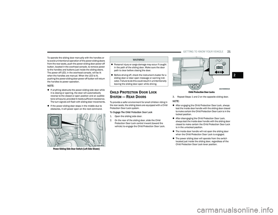
To operate the sliding door manually with the handles or
to avoid unintentional operation of the power sliding doors
from the rear seats, push the power sliding door power off
button, located in the overhead console, to remove power
to the handles and buttons just inside the sliding doors.
The power off LED, in the overhead console, will be lit
when the handles are manual. When the LED is lit,
pushing the power sliding door power off button will return
the handles to power operation.
NOTE:
If anything obstructs the power sliding side door while
it is closing or opening, the door will automatically
reverse to the closed or open position and an audible
tone will sound, provided it meets sufficient resistance.
The turn signals will flash with sliding door movements.
If the power sliding door stops in the middle due to
obstacles, it will power open on the next command.
Power Sliding Side Door Switch (Left Side Shown)
CHILD PROTECTION DOOR LOCK
S
YSTEM — REAR DOORS
To provide a safer environment for small children riding in
the rear seats, the sliding doors are equipped with a Child
Protection Door Lock system.
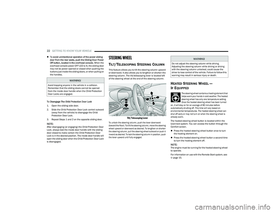
To Engage The Child Protection Door Lock
1. Open the sliding side door.
2. On the rear of the sliding door, slide the Child
Protection Door Lock control inward (toward the
vehicle) to engage the Child Protection Door Lock.
Child Protection Door Locks
3. Repeat Steps 1 and 2 on the opposite sliding door.
NOTE:
After engaging the Child Protection Door Lock, always
test the inside door handle with the sliding door closed
to make certain the Child Protection Door Lock is in the
locked position.
After disengaging the Child Protection Door Lock,
always test the inside door handle with the sliding door
closed to make certain the Child Protection Door Lock
is in the unlocked position.
The inside door handle will not open the sliding door
when the Child Protection Door Lock is engaged.
The power sliding door will operate from the switch
located just inside the sliding door, regardless of the
Child Protection Door Lock lever position.
WARNING!
Personal injury or cargo damage may occur if caught
in the path of the sliding door. Make sure the door
path is clear before closing the door.
Before driving off, check the instrument cluster for a
sliding door or door open message or warning indi -
cator. Failure to do this could result in unintentionally
leaving the sliding door open while driving.
2
23_RUV_OM_EN_US_t.book Page 21
Page 24 of 256
22GETTING TO KNOW YOUR VEHICLE
To avoid unintentional operation of the power sliding
door from the rear seats, push the Sliding Door Power
Off button, located in the overhead console. When the
overhead console power OFF LED is lit, the sliding door
may not be power opened or closed when pushing the
buttons just inside the sliding doors, or when pulling on
the handles.
To Disengage The Child Protection Door Lock
1. Open the sliding side door.
2. Slide the Child Protection Door Lock control outward (away from the vehicle) to disengage the Child
Protection Door Lock.
3. Repeat Steps 1 and 2 on the opposite sliding door.
NOTE:After disengaging (or engaging) the Child Protection Door
Lock, always test the inside door handle with the sliding
door closed to make certain the Child Protection Door
Lock is in the desired position. The inside door handle will
open the sliding door when the Child Protection Door Lock
is disengaged.
STEERING WHEEL
TILT/TELESCOPING STEERING COLUMN
This feature allows you to tilt the steering column upward
or downward. It also allows you to lengthen or shorten the
steering column. The tilt/telescoping lever is located left
of the steering wheel at the end of the steering column.
Tilt/Telescoping Lever
To unlock the steering column, push the lever downward
(toward the floor). To tilt the steering column, move the steering
wheel upward or downward as desired. To lengthen or shorten
the steering column, pull the steering wheel outward or push it
inward as desired. To lock the steering column in position, push
the lever upward until fully engaged.
HEATED STEERING WHEEL —
I
F EQUIPPED
The steering wheel contains a heating element that
helps warm your hands in cold weather. The heated
steering wheel has only one temperature setting.
Once the heated steering wheel has been turned
on, it will stay on for an average of 80 minutes before
automatically shutting off. This time will vary based on
environmental temperatures. The heated steering wheel can
shut off early or may not turn on when the steering wheel is
already warm.
The heated steering wheel button is located within the
Uconnect system. You can access the button through the
Comfort screen.
Press the heated steering wheel button once to turn
the heating element on.
Press the heated steering wheel button a second time
to turn the heating element off.
NOTE:The engine must be running for the heated steering wheel
to operate.
For information on use with the Remote Start system, see
Úpage 15.
WARNING!
Avoid trapping anyone in the vehicle in a collision.
Remember that the sliding doors cannot be opened
from the inside door handle when the Child Protection
Door Locks are engaged.
WARNING!
Do not adjust the steering column while driving.
Adjusting the steering column while driving or driving
with the steering column unlocked, could cause the
driver to lose control of the vehicle. Failure to follow this
warning may result in serious injury or death.
23_RUV_OM_EN_US_t.book Page 22
Page 36 of 256

34GETTING TO KNOW YOUR VEHICLE
Tilting The Seat Up Or Down
The angle of the seat cushion can be adjusted in two
directions. Pull upward or push downward on the front of
the seat switch, the front of the seat cushion will move in
the direction of the switch. Release the switch when the
desired position has been reached.
Reclining The Seatback
The angle of the seatback can be adjusted forward or
rearward. Push the seatback switch forward or rearward,
the seat will move in the direction of the switch. Release
the switch when the desired position is reached.
Power Lumbar — If Equipped
Power Lumbar Switch Location
The front driver’s seat may be equipped with a four-way
lumbar adjustment. The power lumbar switch is located on
the outboard side of the equipped power seat. Push the
switch forward or rearward to increase or decrease the
lumbar support. Push the switch upward or downward to
raise or lower the lumbar support.
HEATED SEATS
Front Heated Seats — If Equipped
The front heated seats control buttons are
located in the touchscreen.
You can choose from HI, LO or off heat settings.
The indicator lights in each switch indicate the level of
heat in use. Two indicator lights will illuminate for HI, one
for LO and none for off.
Press the heated seat button once to turn the HI setting on.
Press the heated seat button a second time to turn the
LO setting on.
Press the heated seat button a third time to turn the
heating elements off.
The level of heat selected will stay on until the operator
changes it.
NOTE:
Once a heat setting is selected, heat will be felt within
two to five minutes.
The engine must be running for the heated seats to
operate.
For information on use with the Remote Start system, see
Úpage 15.
WARNING!
Adjusting a seat while driving may be dangerous.
Moving a seat while driving could result in loss of
control which could cause a collision and serious
injury or death.
Seats should be adjusted before fastening the seat belts
and while the vehicle is parked. Serious injury or death
could result from a poorly adjusted seat belt.
Do not ride with the seatback reclined so that the
shoulder belt is no longer resting against your chest.
In a collision you could slide under the seat belt,
which could result in serious injury or death.
CAUTION!
Do not place any article under a power seat or impede
its ability to move as it may cause damage to the seat
controls. Seat travel may become limited if movement
is stopped by an obstruction in the seat's path.
WARNING!
Persons who are unable to feel pain to the skin
because of advanced age, chronic illness, diabetes,
spinal cord injury, medication, alcohol use, exhaus -
tion or other physical condition must exercise care
when using the seat heater. It may cause burns even
at low temperatures, especially if used for long
periods of time.
Do not place anything on the seat or seatback that
insulates against heat, such as a blanket or cushion.
This may cause the seat heater to overheat. Sitting in
a seat that has been overheated could cause serious
burns due to the increased surface temperature of
the seat.
23_RUV_OM_EN_US_t.book Page 34
Page 39 of 256
GETTING TO KNOW YOUR VEHICLE37
UCONNECT VOICE RECOGNITION —
IF EQUIPPED
INTRODUCING VOICE RECOGNITION
Start using Uconnect Voice Recognition (VR) with these
helpful quick tips. It provides the key Voice Commands
and tips you need to know to control your system.
BASIC VOICE COMMANDS
The following basic Voice Commands can be given at any
point while using your Uconnect system.
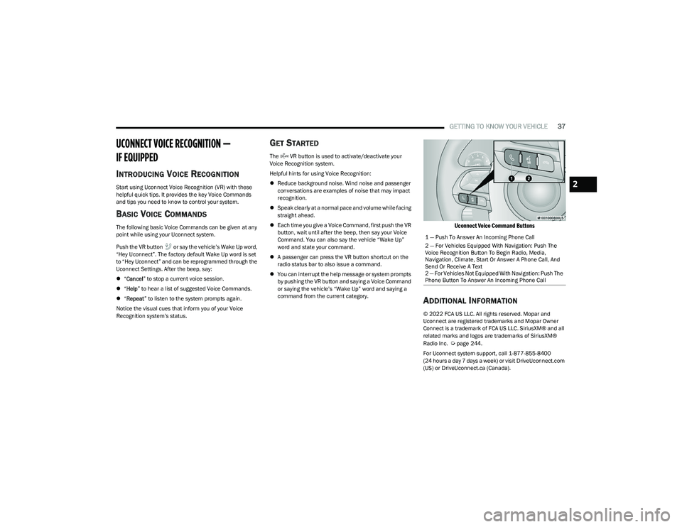
Push the VR button or say the vehicle’s Wake Up word,
“Hey Uconnect”. The factory default Wake Up word is set
to “Hey Uconnect” and can be reprogrammed through the
Uconnect Settings. After the beep, say:
“Cancel ” to stop a current voice session.
“Help ” to hear a list of suggested Voice Commands.
“Repeat ” to listen to the system prompts again.
Notice the visual cues that inform you of your Voice
Recognition system’s status.
GET STARTED
The VR button is used to activate/deactivate your
Voice Recognition system.
Helpful hints for using Voice Recognition:
Reduce background noise. Wind noise and passenger
conversations are examples of noise that may impact
recognition.
Speak clearly at a normal pace and volume while facing
straight ahead.
Each time you give a Voice Command, first push the VR
button, wait until after the beep, then say your Voice
Command. You can also say the vehicle “Wake Up”
word and state your command.
A passenger can press the VR button shortcut on the
radio status bar to also issue a command.
You can interrupt the help message or system prompts
by pushing the VR button and saying a Voice Command
or saying the vehicle’s “Wake Up” word and saying a
command from the current category.
Uconnect Voice Command Buttons
ADDITIONAL INFORMATION
© 2022 FCA US LLC. All rights reserved. Mopar and
Uconnect are registered trademarks and Mopar Owner
Connect is a trademark of FCA US LLC. SiriusXM® and all
related marks and logos are trademarks of SiriusXM®
Radio Inc.
Úpage 244.
For Uconnect system support, call 1-877-855-8400
(24 hours a day 7 days a week) or visit DriveUconnect.com
(US) or DriveUconnect.ca (Canada).
1 — Push To Answer An Incoming Phone Call
2 — For Vehicles Equipped With Navigation: Push The
Voice Recognition Button To Begin Radio, Media,
Navigation, Climate, Start Or Answer A Phone Call, And
Send Or Receive A Text
2 — For Vehicles Not Equipped With Navigation: Push The
Phone Button To Answer An Incoming Phone Call
2
23_RUV_OM_EN_US_t.book Page 37
Page 41 of 256
GETTING TO KNOW YOUR VEHICLE39
POWER MIRRORS — IF EQUIPPED
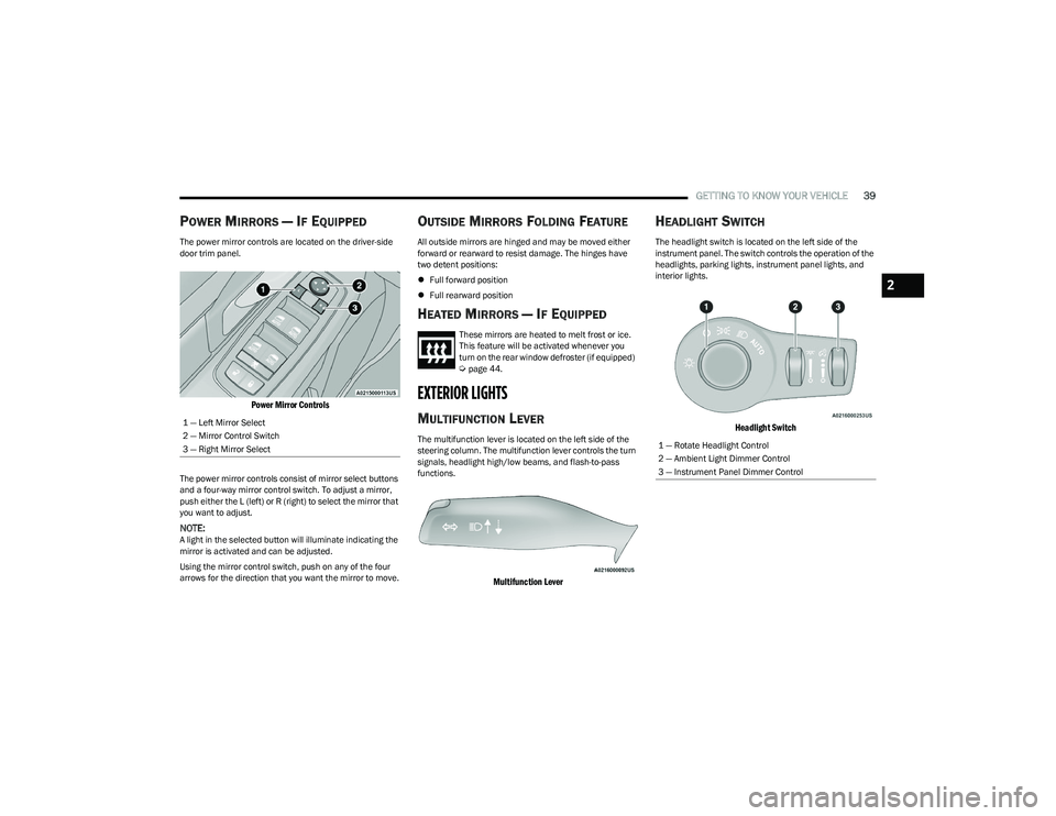
The power mirror controls are located on the driver-side
door trim panel.
Power Mirror Controls
The power mirror controls consist of mirror select buttons
and a four-way mirror control switch. To adjust a mirror,
push either the L (left) or R (right) to select the mirror that
you want to adjust.
NOTE:A light in the selected button will illuminate indicating the
mirror is activated and can be adjusted.
Using the mirror control switch, push on any of the four
arrows for the direction that you want the mirror to move.
OUTSIDE MIRRORS FOLDING FEATURE
All outside mirrors are hinged and may be moved either
forward or rearward to resist damage. The hinges have
two detent positions:
Full forward position
Full rearward position
HEATED MIRRORS — IF EQUIPPED
These mirrors are heated to melt frost or ice.
This feature will be activated whenever you
turn on the rear window defroster (if equipped)
Úpage 44.
EXTERIOR LIGHTS
MULTIFUNCTION LEVER
The multifunction lever is located on the left side of the
steering column. The multifunction lever controls the turn
signals, headlight high/low beams, and flash-to-pass
functions.
Multifunction Lever
HEADLIGHT SWITCH
The headlight switch is located on the left side of the
instrument panel. The switch controls the operation of the
headlights, parking lights, instrument panel lights, and
interior lights.
Headlight Switch
1 — Left Mirror Select
2 — Mirror Control Switch
3 — Right Mirror Select
1 — Rotate Headlight Control
2 — Ambient Light Dimmer Control
3 — Instrument Panel Dimmer Control
2
23_RUV_OM_EN_US_t.book Page 39
Page 47 of 256
GETTING TO KNOW YOUR VEHICLE45
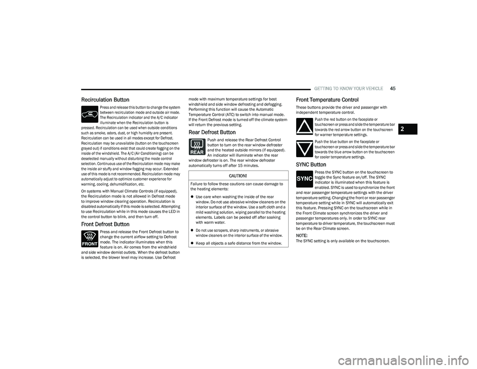
Recirculation Button
Press and release this button to change the system
between recirculation mode and outside air mode.
The Recirculation indicator and the A/C indicator
illuminate when the Recirculation button is
pressed. Recirculation can be used when outside conditions
such as smoke, odors, dust, or high humidity are present.
Recirculation can be used in all modes except for Defrost.
Recirculation may be unavailable (button on the touchscreen
grayed out) if conditions exist that could create fogging on the
inside of the windshield. The A/C (Air Conditioning) can be
deselected manually without disturbing the mode control
selection. Continuous use of the Recirculation mode may make
the inside air stuffy and window fogging may occur. Extended
use of this mode is not recommended. Recirculation mode may
automatically adjust to optimize customer experience for
warming, cooling, dehumidification, etc.
On systems with Manual Climate Controls (if equipped),
the Recirculation mode is not allowed in Defrost mode
to improve window clearing operation. Recirculation is
disabled automatically if this mode is selected. Attempting
to use Recirculation while in this mode causes the LED in
the control button to blink, and then turn off.
Front Defrost Button
Press and release the Front Defrost button to
change the current airflow setting to Defrost
mode. The indicator illuminates when this
feature is on. Air comes from the windshield
and side window demist outlets. When the defrost button
is selected, the blower level may increase. Use Defrost mode with maximum temperature settings for best
windshield and side window defrosting and defogging.
Performing this function will cause the Automatic
Temperature Control (ATC) to switch into manual mode.
If the Front Defrost mode is turned off the climate system
will return the previous setting.
Rear Defrost Button
Push and release the Rear Defrost Control
button to turn on the rear window defroster
and the heated outside mirrors (if equipped).
An indicator will illuminate when the rear
window defroster is on. The rear window defroster
automatically turns off after 15 minutes.
Front Temperature Control
These buttons provide the driver and passenger with
independent temperature control.
Push the red button on the faceplate or
touchscreen or press and slide the temperature bar
towards the red arrow button on the touchscreen
for warmer temperature settings.
Push the blue button on the faceplate or
touchscreen or press and slide the temperature bar
towards the blue arrow button on the touchscreen
for cooler temperature settings.
SYNC Button
Press the SYNC button on the touchscreen to
toggle the Sync feature on/off. The SYNC
indicator is illuminated when this feature is
enabled. SYNC is used to synchronize the front
and rear passenger temperature settings with the driver
temperature setting. Changing the front or rear passenger
temperature setting while in SYNC will automatically exit
this feature. Pressing SYNC on the touchscreen while in
the Front Climate screen synchronizes the driver and
passenger temperatures only. In order to SYNC rear
temperature to driver temperature, the touchscreen must
be on the Rear Climate screen.
NOTE:The SYNC setting is only available on the touchscreen.
CAUTION!
Failure to follow these cautions can cause damage to
the heating elements:
Use care when washing the inside of the rear
window. Do not use abrasive window cleaners on the
interior surface of the window. Use a soft cloth and a
mild washing solution, wiping parallel to the heating
elements. Labels can be peeled off after soaking
with warm water.
Do not use scrapers, sharp instruments, or abrasive
window cleaners on the interior surface of the window.
Keep all objects a safe distance from the window.
2
23_RUV_OM_EN_US_t.book Page 45
Page 48 of 256
46GETTING TO KNOW YOUR VEHICLE
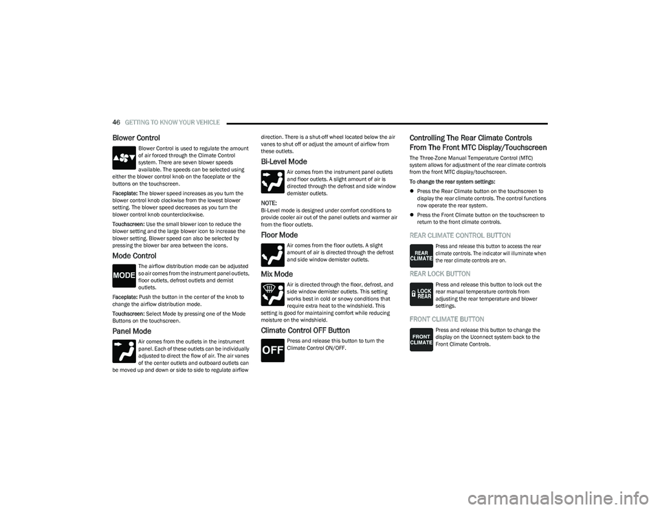
Blower Control
Blower Control is used to regulate the amount
of air forced through the Climate Control
system. There are seven blower speeds
available. The speeds can be selected using
either the blower control knob on the faceplate or the
buttons on the touchscreen.
Faceplate: The blower speed increases as you turn the
blower control knob clockwise from the lowest blower
setting. The blower speed decreases as you turn the
blower control knob counterclockwise.
Touchscreen: Use the small blower icon to reduce the
blower setting and the large blower icon to increase the
blower setting. Blower speed can also be selected by
pressing the blower bar area between the icons.
Mode Control
The airflow distribution mode can be adjusted
so air comes from the instrument panel outlets,
floor outlets, defrost outlets and demist
outlets.
Faceplate: Push the button in the center of the knob to
change the airflow distribution mode.
Touchscreen: Select Mode by pressing one of the Mode
Buttons on the touchscreen.
Panel Mode
Air comes from the outlets in the instrument
panel. Each of these outlets can be individually
adjusted to direct the flow of air. The air vanes
of the center outlets and outboard outlets can
be moved up and down or side to side to regulate airflow direction. There is a shut-off wheel located below the air
vanes to shut off or adjust the amount of airflow from
these outlets.
Bi-Level Mode
Air comes from the instrument panel outlets
and floor outlets. A slight amount of air is
directed through the defrost and side window
demister outlets.
NOTE:Bi-Level mode is designed under comfort conditions to
provide cooler air out of the panel outlets and warmer air
from the floor outlets.
Floor Mode
Air comes from the floor outlets. A slight
amount of air is directed through the defrost
and side window demister outlets.
Mix Mode
Air is directed through the floor, defrost, and
side window demister outlets. This setting
works best in cold or snowy conditions that
require extra heat to the windshield. This
setting is good for maintaining comfort while reducing
moisture on the windshield.
Climate Control OFF Button
Press and release this button to turn the
Climate Control ON/OFF.
Controlling The Rear Climate Controls
From The Front MTC Display/Touchscreen
The Three-Zone Manual Temperature Control (MTC)
system allows for adjustment of the rear climate controls
from the front MTC display/touchscreen.
To change the rear system settings:
Press the Rear Climate button on the touchscreen to
display the rear climate controls. The control functions
now operate the rear system.
Press the Front Climate button on the touchscreen to
return to the front climate controls.
REAR CLIMATE CONTROL BUTTON
Press and release this button to access the rear
climate controls. The indicator will illuminate when
the rear climate controls are on.
REAR LOCK BUTTON
Press and release this button to lock out the
rear manual temperature controls from
adjusting the rear temperature and blower
settings.
FRONT CLIMATE BUTTON
Press and release this button to change the
display on the Uconnect system back to the
Front Climate Controls.
23_RUV_OM_EN_US_t.book Page 46
Page 49 of 256

GETTING TO KNOW YOUR VEHICLE47
REAR TEMPERATURE CONTROL
These buttons provide the rear passengers with
independent temperature control.
Push the up arrow button on the touchscreen
to increase the temperature.
Push the down arrow button on the
touchscreen to decrease the temperature.
NOTE:
When the SYNC feature is active, the passenger’s temperature
moves up and down with the driver’s temperature.
SYNC BUTTON
Press the SYNC button on the touchscreen to
toggle the SYNC feature on/off. The SYNC
indicator is illuminated when this feature is
enabled. SYNC is used to synchronize the front
and rear passenger temperature settings with the driver
temperature setting. Changing the front or rear passenger
temperature setting while in SYNC exits this feature.
NOTE:The SYNC setting is only available on the touchscreen.
BLOWER CONTROL
Blower Control is used to regulate the amount of air
forced through the Climate Control system. There
are seven blower speeds available. Adjusting the
blower causes automatic mode to switch to manual
operation. The speeds can be selected using the buttons on the
touchscreen.
PANEL MODE
Press this button on the touchscreen to change
the air distribution mode to Panel Mode.
In Panel Mode, air comes from the outlets in
the headliner. Each of these outlets can be
individually adjusted to direct the flow of air. Moving the
air vanes of the outlets to one side will shut off the airflow.
BI-LEVEL MODE
Press this button on the touchscreen to change
the air distribution mode to Bi-Level Mode. In
Bi-Level Mode, air comes from the headliner
outlets and floor outlets.
NOTE:Bi-Level Mode is designed under comfort conditions to
provide cooler air out of the panel outlets and warmer air
from the floor outlets.
FLOOR MODE
Press this button on the touchscreen to change
the air distribution mode to Floor Mode. In Floor
Mode, air comes from the floor outlets.
REAR PASSENGER CLIMATE CONTROL OFF
BUTTON
Press and release this button to turn the Rear
Climate Controls off.
Rear Manual Temperature Control (MTC)
The rear Manual Temperature Control (MTC) system has
floor air outlets at the rear right side of the third row seats
and overhead outlets at each outboard rear seating
position. The system provides heated air through the floor
outlets or cool, dehumidified air through the headliner
outlets.
The rear system temperature control buttons are located
on the headliner on the passenger side of the vehicle.
Rear Manual Climate Controls
CAUTION!
Interior air enters the Rear Automatic Temperature
Control system through an intake grille, located in the
floor under the passengers’ seats. Do not block or
place objects directly in front of the inlet grille or heater
outlets. The electrical system could overload causing
damage to the blower motor.
2
23_RUV_OM_EN_US_t.book Page 47