clutch CHRYSLER VOYAGER 2023 Owners Manual
[x] Cancel search | Manufacturer: CHRYSLER, Model Year: 2023, Model line: VOYAGER, Model: CHRYSLER VOYAGER 2023Pages: 256, PDF Size: 13.97 MB
Page 85 of 256
STARTING AND OPERATING83
The following indicators should be used to ensure that you
have properly engaged the transmission into the PARK
position:
Look at the transmission gear position display and
verify that it indicates the PARK position (P), and is not
blinking.
With the brake pedal released, verify that the gear
selector will not move out of PARK.
REVERSE (R)
This range is for moving the vehicle backward. Shift into
REVERSE only after the vehicle has come to a complete stop.
NEUTRAL (N)
Use this range when the vehicle is standing for prolonged
periods with the engine running. The engine may be
started in this range. Apply the parking brake and shift the
transmission into PARK if you must exit the vehicle.
DRIVE (D)
This range should be used for most city and highway driving. It
provides the smoothest upshifts and downshifts, and the best
fuel economy. The transmission automatically upshifts through
all forward gears. The DRIVE position provides optimum driving
characteristics under all normal operating conditions.
If the transmission temperature exceeds normal operating
limits, the transmission controller may modify the transmission
shift schedule, reduce engine torque, and/or expand the range
of torque converter clutch engagement. This is done to prevent
transmission damage due to overheating.
If the transmission becomes extremely hot, the
Transmission Temperature Warning Light will illuminate, a
warning message will appear in the instrument cluster,
and the transmission may operate differently until the
transmission cools down.
During cold temperatures, transmission operation may be
modified depending on engine and transmission temperature
as well as vehicle speed. This feature improves warm-up time
of the engine and transmission to achieve maximum efficiency.
Engagement of the torque converter clutch, and shifts into
EIGHTH or NINTH gear, are inhibited until the transmission fluid
is warm
Ú
page 84. Normal operation will resume once the
transmission temperature has risen to a suitable level.
LOW (L)
Use this range for engine braking when descending
very steep grades. In this range, the transmission will
downshift for increased engine braking. To access the
LOW position, push down on the gear selector and rotate
it fully clockwise.
Transmission Limp Home Mode
Transmission function is monitored electronically for
abnormal conditions. If a condition is detected that could
result in transmission damage, Transmission Limp Home
Mode is activated. In this mode, the transmission may
operate only in a fixed gear, or may remain in NEUTRAL.
The Malfunction Indicator Light (MIL) may be illuminated.
Limp Home Mode may allow the vehicle to be driven to an
authorized dealer for service without damaging the
transmission.
CAUTION!
Before moving the transmission gear selector out of
PARK, you must start the engine, and also press the
brake pedal. Otherwise, damage to the gear selector
could result.
DO NOT race the engine when shifting from PARK
or NEUTRAL into another gear range, as this can
damage the drivetrain.
WARNING!
Do not coast in NEUTRAL and never turn off the ignition to
coast down a hill. These are unsafe practices that limit your
response to changing traffic or road conditions. You might
lose control of the vehicle and have a collision.
CAUTION!
Towing the vehicle, coasting, or driving for any other
reason with the transmission in NEUTRAL can cause
severe transmission damage.
If Recreational Towing
Úpage 101.
If Towing A Disabled Vehicle
Úpage 190.
4
23_RUV_OM_EN_US_t.book Page 83
Page 86 of 256
84STARTING AND OPERATING
In the event of a momentary problem, the transmission
can be reset to regain all forward gears by performing the
following steps:
1. Stop the vehicle.
2. Shift the transmission into PARK, if possible. If not,
shift the transmission to NEUTRAL.
3. Push and hold the ignition switch until the engine turns off.
4. Wait approximately 30 seconds.
5. Restart the engine.
6. Shift into the desired gear range. If the problem is no longer detected, the transmission will return to
normal operation.
NOTE:
Even if the transmission can be reset, we recommend that you
visit an authorized dealer at your earliest possible convenience.
An authorized dealer has diagnostic equipment to assess the
condition of your transmission. If the transmission cannot be
reset, authorized dealer service is required.
Torque Converter Clutch
A feature designed to improve fuel economy has been
included in the automatic transmission on your vehicle.
A clutch within the torque converter engages
automatically at calibrated speeds. This may result in a
slightly different feeling or response during normal
operation in the upper gears. When the vehicle speed
drops or during some accelerations, the clutch
automatically disengages.
NOTE:The torque converter clutch will not engage until the
engine and/or transmission is warm (usually after 1 to
3 miles [2 to 5 km] of driving). Because the engine speed
is higher when the torque converter clutch is not engaged,
it may seem as if the transmission is not shifting properly
when the vehicle is cold. This is normal. The torque
converter clutch will function normally once the powertrain
is sufficiently warm.
ACTIVE NOISE CANCELLATION
Your vehicle is equipped with an Active Noise Cancellation
system. This system is designed to address exhaust and engine
noise. The system relies on four microphones embedded in the
headliner, which monitor exhaust and engine noise, and assists
an onboard frequency generator, which creates counteracting
sound waves in the audio system’s speakers. This helps keep
the vehicle quiet at idle and during drive.
POWER STEERING
The electric power steering system will provide increased
vehicle response and ease of maneuverability. The power
steering system adapts to different driving conditions.
If the Steering icon is displayed and the “POWER STEERING
SYSTEM OVER TEMP” message is displayed on the instrument
cluster screen, this indicates an over temperature condition in
the power steering system. Once driving conditions are safe,
pull over and let the vehicle idle for a few moments until the
icon and message turn off
Ú
page 67.
If the “SERVICE POWER STEERING" or "POWER
STEERING ASSIST OFF - SERVICE SYSTEM”
message and a steering wheel icon are displayed
on the instrument cluster screen, it indicates that
the vehicle needs to be taken to an authorized dealer for
service. It is likely the vehicle has lost power steering
assistance
Ú
page 67.
NOTE:
Even if the power steering assistance is no longer oper -
ational, it is still possible to steer the vehicle. Under
these conditions there will be a substantial increase in
steering effort, especially at low speeds and during
parking maneuvers.
The power steering system is fully electric; it requires
no power steering fluid.
If the condition persists, see an authorized dealer for
service.
WARNING!
Continued operation with reduced assist could pose a
safety risk to yourself and others. Service should be
obtained as soon as possible.
23_RUV_OM_EN_US_t.book Page 84
Page 169 of 256
SAFETY167
SAFETY TIPS
TRANSPORTING PASSENGERS
NEVER TRANSPORT PASSENGERS IN THE CARGO AREA.
TRANSPORTING PETS
Air Bags deploying in the front seat could harm your pet.
An unrestrained pet will be thrown about and possibly
injured, or injure a passenger during panic braking or in a
collision.
Pets should be restrained in the rear seat (if equipped) in pet
harnesses or pet carriers that are secured by seat belts.
CONNECTED VEHICLES
Privacy of any wireless and wired communications cannot
be assured. Third parties may unlawfully intercept
information and private communications without your
consent. For further information, refer to “Data Collection
& Privacy” in your Uconnect Owner’s Manual Supplement
or “Onboard Diagnostic System (OBD II) Cybersecurity”
Úpage 73.
SAFETY CHECKS YOU SHOULD MAKE
I
NSIDE THE VEHICLE
Seat Belts
Inspect the seat belt system periodically, checking for
cuts, frays, and loose parts. Damaged parts must be
replaced immediately. Do not disassemble or modify the
system.
If your vehicle is involved in a collision, or if you have
questions regarding seat belt or retractor conditions, take
your vehicle to an authorized FCA dealer or authorized FCA
Certified Collision Care Program facility for inspection.
Air Bag Warning Light
The Air Bag Warning Light will turn on for
four to eight seconds as a bulb check when the
ignition switch is first placed in the ON/RUN
mode. If the light is either not on during
starting, stays on, or turns on while driving, have the
system inspected at an authorized dealer as soon as
possible. After the bulb check, this light will illuminate with
a single chime when a fault with the Air Bag System has
been detected. It will stay on until the fault is removed.
If the light comes on intermittently or remains on while
driving, have an authorized dealer service the vehicle
immediately
Úpage 134.
Defroster
Check operation by selecting the defrost mode and place the
blower control on high speed. You should be able to feel the air
directed against the windshield. See an authorized dealer for
service if your defroster is inoperable.
Floor Mat Safety Information
Always use floor mats designed to fit your vehicle. Only use
a floor mat that does not interfere with the operation of the
accelerator, brake or clutch pedals. Only use a floor mat
that is securely attached using the floor mat fasteners
so it cannot slip out of position and interfere with the
accelerator, brake or clutch pedals or impair safe
operation of your vehicle in other ways.
WARNING!
Do not leave children or animals inside parked vehi -
cles in hot weather. Interior heat buildup may cause
serious injury or death.
It is extremely dangerous to ride in a cargo area,
inside or outside of a vehicle. In a collision, people
riding in these areas are more likely to be seriously
injured or killed.
Do not allow people to ride in any area of your vehicle
that is not equipped with seats and seat belts.
Be sure everyone in your vehicle is in a seat and
using a seat belt properly.
WARNING!
It is not possible to know or to predict all of the possible
outcomes if your vehicle’s systems are breached. It may
be possible that vehicle systems, including safety
related systems, could be impaired or a loss of vehicle
control could occur that may result in an accident
involving serious injury or death.
6
23_RUV_OM_EN_US_t.book Page 167
Page 170 of 256
168SAFETY
(Continued)
PERIODIC SAFETY CHECKS YOU SHOULD
M
AKE OUTSIDE THE VEHICLE
Tires
Examine tires for excessive tread wear and uneven wear
patterns. Check for stones, nails, glass, or other objects
lodged in the tread or sidewall. Inspect the tread for cuts
and cracks. Inspect sidewalls for cuts, cracks, and bulges.
Check the lug nut/bolt torque for tightness. Check the
tires (including spare) for proper cold inflation pressure.
Lights
Have someone observe the operation of brake lights and
exterior lights while you work the controls. Check turn
signal and high beam indicator lights on the instrument
panel.
Door Latches
Check for proper closing, latching, and locking.
Fluid Leaks
Check area under the vehicle after overnight parking for
fuel, coolant, oil, or other fluid leaks. Also, if gasoline
fumes are detected or if fuel or brake fluid leaks are
suspected, the cause should be located and corrected
immediately.
WARNING!
An improperly attached, damaged, folded, or stacked
floor mat, or damaged floor mat fasteners may cause
your floor mat to interfere with the accelerator, brake, or
clutch pedals and cause a loss of vehicle control. To
prevent SERIOUS INJURY or DEATH:
ALWAYS securely attach your floor mat
using the floor mat fasteners. DO NOT
install your floor mat upside down or turn
your floor mat over. Lightly pull to confirm
mat is secured using the floor mat fasteners on a
regular basis.
ALWAYS REMOVE THE EXISTING FLOOR
MAT FROM THE VEHICLE before installing
any other floor mat. NEVER install or stack
an additional floor mat on top of an
existing floor mat.
ONLY install floor mats designed to fit your vehicle.
NEVER install a floor mat that cannot be properly
attached and secured to your vehicle. If a floor mat needs
to be replaced, only use a FCA approved floor mat for the
specific make, model, and year of your vehicle.
ONLY use the driver’s side floor mat on the driver’s side
floor area. To check for interference, with the vehicle
properly parked with the engine off, fully depress the
accelerator, the brake, and the clutch pedal (if present) to
check for interference. If your floor mat interferes with the
operation of any pedal, or is not secure to the floor,
remove the floor mat from the vehicle and place the floor
mat in your trunk.
ONLY use the passenger’s side floor mat on the
passenger’s side floor area.
ALWAYS make sure objects cannot fall or slide into
the driver’s side floor area when the vehicle is
moving. Objects can become trapped under acceler -
ator, brake, or clutch pedals and could cause a loss
of vehicle control.
NEVER place any objects under the floor mat (e.g.,
towels, keys, etc.). These objects could change the
position of the floor mat and may cause interference
with the accelerator, brake, or clutch pedals.
If the vehicle carpet has been removed and
re-installed, always properly attach carpet to the floor
and check the floor mat fasteners are secure to the
vehicle carpet. Fully depress each pedal to check for
interference with the accelerator, brake, or clutch
pedals then re-install the floor mats.
It is recommended to only use mild soap and water
to clean your floor mats. After cleaning, always check
your floor mat has been properly installed and is
secured to your vehicle using the floor mat fasteners
by lightly pulling mat.
WARNING!
23_RUV_OM_EN_US_t.book Page 168
Page 212 of 256
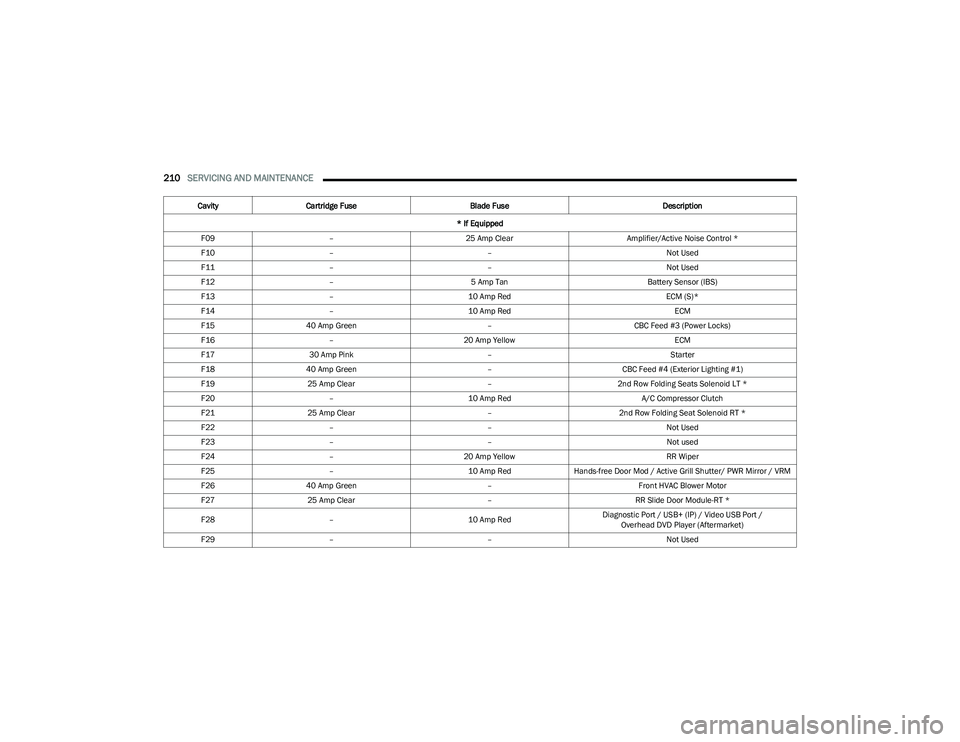
210SERVICING AND MAINTENANCE
F09 – 25 Amp Clear Amplifier/Active Noise Control *
F10 – – Not Used
F11 – – Not Used
F12 – 5 Amp Tan Battery Sensor (IBS)
F13 – 10 Amp Red ECM (S)*
F14 – 10 Amp Red ECM
F15 40 Amp Green –CBC Feed #3 (Power Locks)
F16 – 20 Amp Yellow ECM
F17 30 Amp Pink – Starter
F18 40 Amp Green –CBC Feed #4 (Exterior Lighting #1)
F19 25 Amp Clear –2nd Row Folding Seats Solenoid LT *
F20 – 10 Amp Red A/C Compressor Clutch
F21 25 Amp Clear –2nd Row Folding Seat Solenoid RT *
F22 – – Not Used
F23 – – Not used
F24 – 20 Amp Yellow RR Wiper
F25 – 10 Amp RedHands-free Door Mod / Active Grill Shutter/ PWR Mirror / VRM
F26 40 Amp Green –Front HVAC Blower Motor
F27 25 Amp Clear –RR Slide Door Module-RT *
F28 – 10 Amp RedDiagnostic Port / USB+ (IP) / Video USB Port /
Overhead DVD Player (Aftermarket)
F29 – – Not Used
Cavity
Cartridge Fuse Blade Fuse Description
* If Equipped
23_RUV_OM_EN_US_t.book Page 210