Switch Citroen BERLINGO 2005 1.G User Guide
[x] Cancel search | Manufacturer: CITROEN, Model Year: 2005, Model line: BERLINGO, Model: Citroen BERLINGO 2005 1.GPages: 462, PDF Size: 10.48 MB
Page 291 of 462
![Citroen BERLINGO 2005 1.G User Guide Downloaded from www.Manualslib.com manuals search engine 285
INJECTION
CHECKS: LOW PRESSURE FUEL SUPPLY CIRCUIT
Tools.
[1] Ø 10 mm low pressure connector: 4215-T
[2] Pressure gauge for testing boost Citroen BERLINGO 2005 1.G User Guide Downloaded from www.Manualslib.com manuals search engine 285
INJECTION
CHECKS: LOW PRESSURE FUEL SUPPLY CIRCUIT
Tools.
[1] Ø 10 mm low pressure connector: 4215-T
[2] Pressure gauge for testing boost](/img/9/4138/w960_4138-290.png)
Downloaded from www.Manualslib.com manuals search engine 285
INJECTION
CHECKS: LOW PRESSURE FUEL SUPPLY CIRCUIT
Tools.
[1] Ø 10 mm low pressure connector: 4215-T
[2] Pressure gauge for testing boost pressure: 4073-T.A Toolkit 4073-T
IMPERATIVE: Respect the safety and cleanliness specific to high pressure diesel injection
engines.
Remove the air filter duct.
Link tool [1]in series, downstream of the injectors, between the fuel high pressure pump and the
fuel filter at «a»and «b».
WARNING: Any checking of pressure downstream of the fuel filter is prohibited.
Switch on the ignition.
ESSENTIAL: Check that the tool [2] is clean.
Check the negative pressure according to the table below:
Vacuum Observations
10 ± 05 cmhgEngine driven by the starter motor
20 ± 20 cmhgEngine running under full load
60 ± 05 cmhgSupply circuit obstructed
(full tank strainer, piping, fuel filter
B1BP2PHC
Engines: 9HZ - 9HY
XSARA PICASSO
Angl.-t2-page283-305-2005 9/01/06 10:18 Page 285
Page 294 of 462
![Citroen BERLINGO 2005 1.G User Guide Downloaded from www.Manualslib.com manuals search engine 288
INJECTION
CHECKS: LOW PRESSURE FUEL SUPPLY CIRCUIT
Tools.
[1] Ø 10 mm low pressure connector: 4215-T
[2] Ø 8 mmlow pressure connector: 42 Citroen BERLINGO 2005 1.G User Guide Downloaded from www.Manualslib.com manuals search engine 288
INJECTION
CHECKS: LOW PRESSURE FUEL SUPPLY CIRCUIT
Tools.
[1] Ø 10 mm low pressure connector: 4215-T
[2] Ø 8 mmlow pressure connector: 42](/img/9/4138/w960_4138-293.png)
Downloaded from www.Manualslib.com manuals search engine 288
INJECTION
CHECKS: LOW PRESSURE FUEL SUPPLY CIRCUIT
Tools.
[1] Ø 10 mm low pressure connector: 4215-T
[2] Ø 8 mmlow pressure connector: 4218-T
[3]Pressure gauge for testing boost pressure: 4073-T Kit 4073-T
Connect the tool [1]between the booster pump and the fuel filter
(white mark at "a" on the fuel
supply pipe).
Connect the tool [2]downstream of the diesel injectors, between the high pressure fuel pump and
the fuel filter
(green mark at "b" on the fuel return pipe).
WARNING: Any check of pressure downstream of the fuel filter is PROHIBITED.
Checks on pressure: static.
- Switch on ignition.
For 3 seconds
(normal functioning):
- Fuel supply pressure shown by the pressure gauge [3] = 1.8 ± 0.4 bar.
- Fuel return pressure shown by the pressure gauge [3] = 0.5 ± 0.4 bar.
B1BP1TWD
Engines: RHY - RHZ
XSARA PICASSO
Angl.-t2-page283-305-2005 9/01/06 10:18 Page 288
Page 305 of 462
![Citroen BERLINGO 2005 1.G User Guide Downloaded from www.Manualslib.com manuals search engine 299
INJECTION
CHECKING THE AIR SUPPLY CIRCUIT
B1BP33ZC
B1BP340C
Engine: RHR
B1BP341C
B1BP342C
Tool.
[1]Manual pressure-vacuum pump: FACOM DA 16 Citroen BERLINGO 2005 1.G User Guide Downloaded from www.Manualslib.com manuals search engine 299
INJECTION
CHECKING THE AIR SUPPLY CIRCUIT
B1BP33ZC
B1BP340C
Engine: RHR
B1BP341C
B1BP342C
Tool.
[1]Manual pressure-vacuum pump: FACOM DA 16](/img/9/4138/w960_4138-304.png)
Downloaded from www.Manualslib.com manuals search engine 299
INJECTION
CHECKING THE AIR SUPPLY CIRCUIT
B1BP33ZC
B1BP340C
Engine: RHR
B1BP341C
B1BP342C
Tool.
[1]Manual pressure-vacuum pump: FACOM DA 16
IMPERATIVE: Respect the safety and cleanliness specific to high pressure diesel
injection engines.
WARNING: After switching off the ignition, wait 15 minutes before disconnecting
the battery
(to guarantee memorisation of the initialisations of the different ECUS).
Checking the vacuum source
(vacuum pump).
Connect the tool [1] on the take-off «a».
Start the engine.
The value should be: 1 ± 0,2.
Turbocharging pressure electrovalve.
Connect the tool [1]on the vacuum supply «b»of the electrovalve (1).
Start the engine.
The value should be: 1 ± 0,2.
Cold air circuit electrovalve.
Connect the tool [1]on the vacuum supply «c»of the electrovalve (2).
Start the engine.
The value should be: 1 ± 0,2.
Warm air circuit electrovalve.
Connect the tool [1]on the vacuum supply «d»of the electrovalve (3).
Start the engine.
The value should be: 1 ± 0,2.
C4
Angl.-t2-page283-305-2005 9/01/06 10:18 Page 299
Page 325 of 462
Downloaded from www.Manualslib.com manuals search engine 319
CLUTCH
GEARBOX
TRANSMISSION
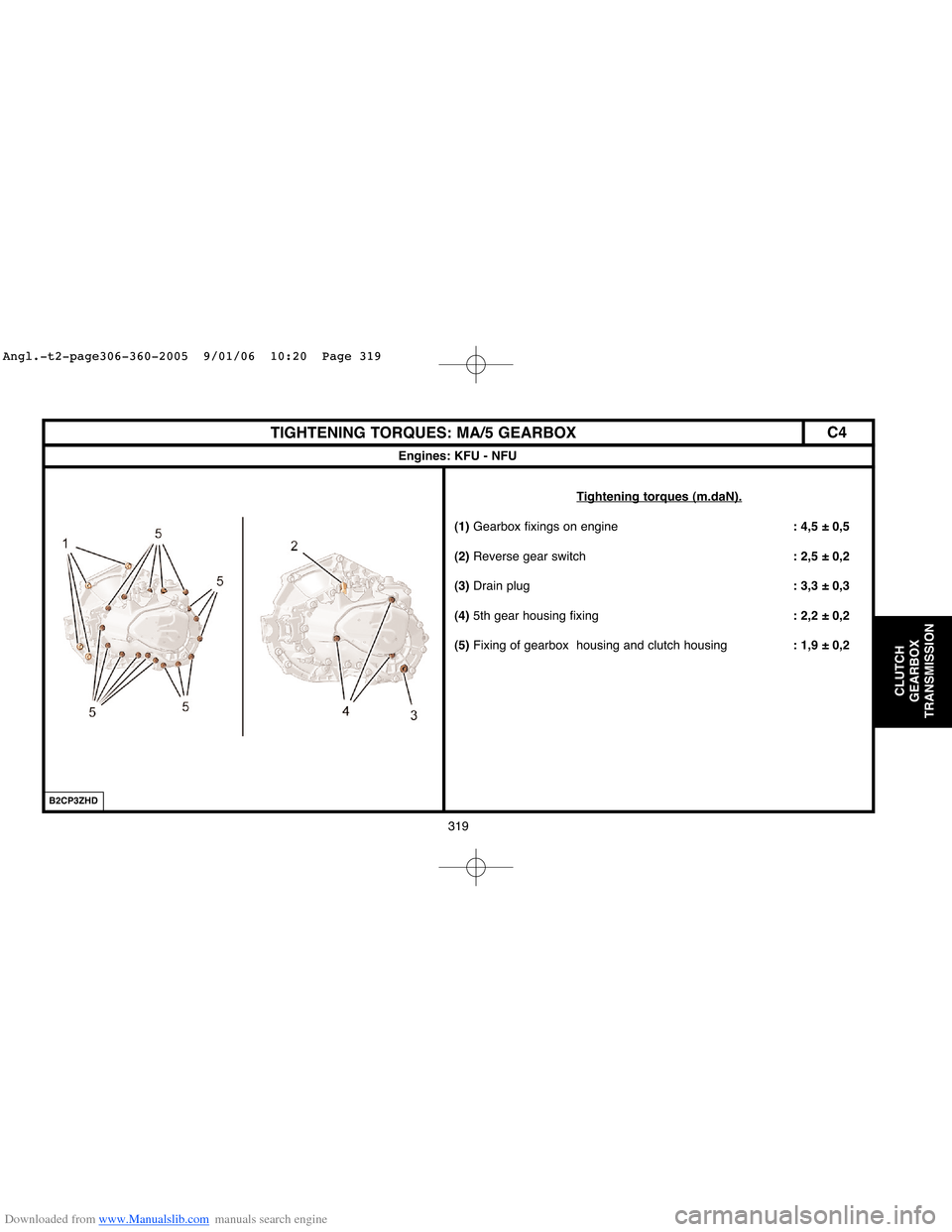
TIGHTENING TORQUES: MA/5 GEARBOX
Engines: KFU - NFU
Tightening torques (m.daN).
(1)Gearbox fixings on engine: 4,5 ± 0,5
(2)Reverse gear switch: 2,5 ± 0,2
(3)Drain plug: 3,3 ± 0,3
(4)5th gear housing fixing: 2,2 ± 0,2
(5)Fixing of gearbox housing and clutch housing: 1,9 ± 0,2
B2CP3ZHD
C4
Angl.-t2-page306-360-2005 9/01/06 10:20 Page 319
Page 329 of 462
Downloaded from www.Manualslib.com manuals search engine 323
CLUTCH
GEARBOX
TRANSMISSION
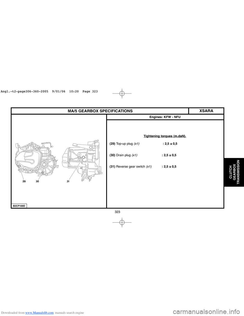
MA/5 GEARBOX SPECIFICATIONS
Engines: KFW - NFU
Tightening torques (m.daN).
(29) Top-up plug (x1): 2,5 ± 0,5
(30)Drain plug
(x1): 2,5 ± 0,5
(31)Reverse gear switch
(x1): 2,5 ± 0,5
B2CP169D
XSARA
Angl.-t2-page306-360-2005 9/01/06 10:20 Page 323
Page 330 of 462
Downloaded from www.Manualslib.com manuals search engine 324
CLUTCH
GEARBOX
TRANSMISSION
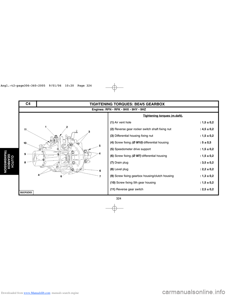
TIGHTENING TORQUES: BE4/5 GEARBOX
Engines: RFN - RFK - 9HX - 9HY - 9HZ
Tightening torques (m.daN).
(1)Air vent hole : 1,5 ± 0,2
(2)Reverse gear rocker switch shaft fixing nut: 4,5 ± 0,2
(3) Differential housing fixing nut: 1,5 ± 0,2
(4)Screw fixing
(Ø M10)differential housing: 5 ± 0,5
(5)Speedometer drive support: 1,5 ± 0,2
(6)Screw fixing
(Ø M7)differential housing: 1,5 ± 0,2
(7)Drain plug : 3,5 ± 0,2
(8)Level plug: 2,2 ± 0,2
(9)Screw fixing gearbox housing/clutch housing: 1,3 ± 0,2
(10) Screw fixing 5th gear housing: 1,5 ± 0,2
(11)Reverse gear switch: 2,5 ± 0,2
B2CP3ZXD
C4
Angl.-t2-page306-360-2005 9/01/06 10:20 Page 324
Page 333 of 462
Downloaded from www.Manualslib.com manuals search engine 327
CLUTCH
GEARBOX
TRANSMISSION
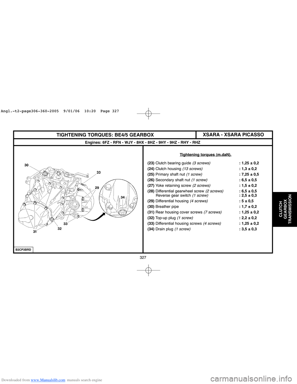
TIGHTENING TORQUES: BE4/5 GEARBOX
Engines: 6FZ - RFN - WJY - 8HX - 8HZ - 9HY - 9HZ - RHY - RHZ
T
ightening torques (m.daN).
(23)Clutch bearing guide (3 screws): 1,25 ± 0,2
(24)Clutch housing
(13 screws): 1,3 ± 0,2
(25)Primary shaft nut
(1 screw): 7,25 ± 0,5
(26)Secondary shaft nut
(1 screw): 6,5 ± 0,5
(27)Yoke retaining screw
(2 screws): 1,5 ± 0,2
(28)Differential gearwheel screw
(2 screws): 6,5 ± 0,5
Reverse gear switch (1 screw): 2,5 ± 0,3
(29)Differential housing
(4 screws): 5 ± 0,5
(30)Breather pipe: 1,7 ± 0,2
(31)Rear housing cover screws
(7 screws): 1,25 ± 0,2
(32)Top-up plug
(1 screw): 2,2 ± 0,2
(33) Differential housing screws
(4 screws): 1,25 ± 0,2
(34)Drain plug
(1 screw): 3,5 ± 0,3
B2CP3BRD
XSARA - XSARA PICASSO
Angl.-t2-page306-360-2005 9/01/06 10:20 Page 327
Page 335 of 462
Downloaded from www.Manualslib.com manuals search engine 329
CLUTCH
GEARBOX
TRANSMISSION
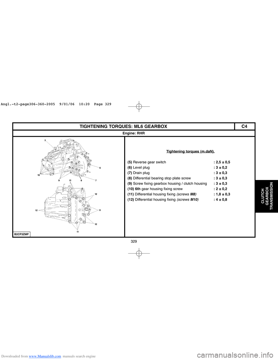
TIGHTENING TORQUES: ML6 GEARBOX
Engine: RHR
Tightening torques (m.daN).
(5)Reverse gear switch: 2,5 ± 0,5
(6)Level plug: 3 ± 0,2
(7)Drain plug: 3 ± 0,3
(8)Differential bearing stop plate screw: 3 ± 0,3
(9)Screw fixing gearbox housing / clutch housing: 3 ± 0,3
(10) 6thgear housing fixing screw: 2 ± 0,2
(11)Differential housing fixing
(screws M8): 1,8 ± 0,3
(12)Differential housing fixing
(screws M10): 4 ± 0,8
B2CP3ZMP
C4
Angl.-t2-page306-360-2005 9/01/06 10:20 Page 329
Page 355 of 462
Downloaded from www.Manualslib.com manuals search engine 349
CLUTCH
GEARBOX
TRANSMISSION
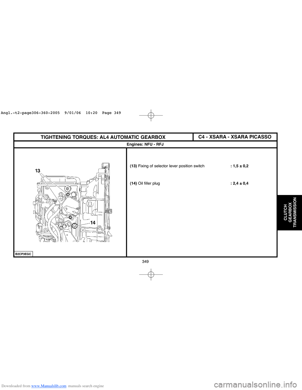
Engines: NFU - RFJ
B2CP3EGC
(13)Fixing of selector lever position switch: 1,5 ± 0,2
(14)Oil filler plug: 2,4 ± 0,4
TIGHTENING TORQUES: AL4 AUTOMATIC GEARBOXC4 - XSARA - XSARA PICASSO
Angl.-t2-page306-360-2005 9/01/06 10:20 Page 349
Page 357 of 462
Downloaded from www.Manualslib.com manuals search engine 351
CLUTCH
GEARBOX
TRANSMISSION
RECOMMENDATIONS/PRECAUTIONS: AL4 AUTOMATIC GEARBOX (SHIFT LOCK)
Engines: NFU - RFJ
C5FP0NZC
C5FP0P0C
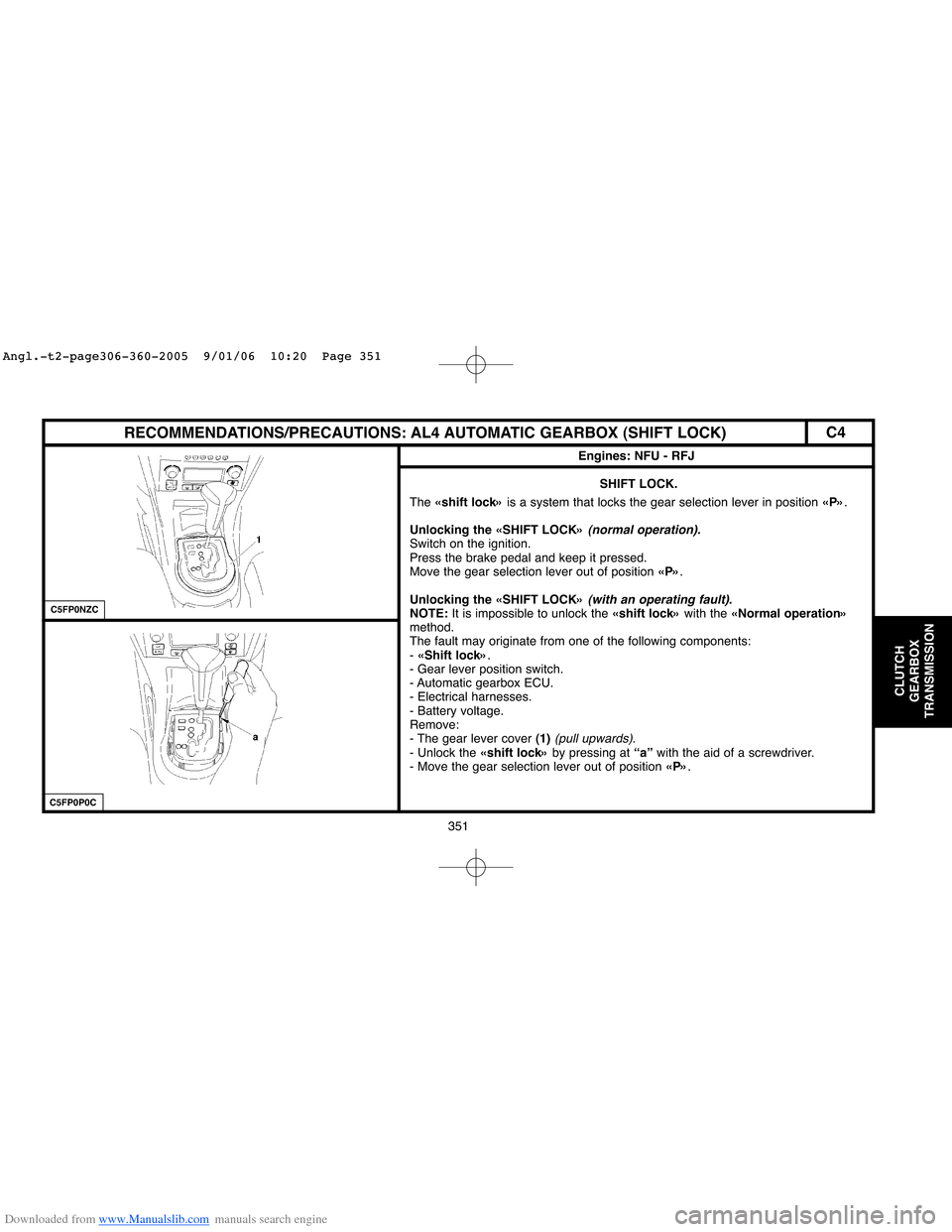
SHIFT LOCK.
The «shift lock»is a system that locks the gear selection lever in position «P».
Unlocking the «SHIFT LOCK»
(normal operation).Switch on the ignition.
Press the brake pedal and keep it pressed.
Move the gear selection lever out of position «P».
Unlocking the «SHIFT LOCK»
(with an operating fault).
NOTE:It is impossible to unlock the «shift lock»with the «Normal operation»
method.
The fault may originate from one of the following components:
- «Shift lock».
- Gear lever position switch.
- Automatic gearbox ECU.
- Electrical harnesses.
- Battery voltage.
Remove:
- The gear lever cover (1)
(pull upwards).
- Unlock the «shift lock»by pressing at “a”with the aid of a screwdriver.
- Move the gear selection lever out of position «P».
C4
Angl.-t2-page306-360-2005 9/01/06 10:20 Page 351