change wheel CITROEN C-ELYSÉE 2018 Handbook (in English)
[x] Cancel search | Manufacturer: CITROEN, Model Year: 2018, Model line: C-ELYSÉE, Model: CITROEN C-ELYSÉE 2018Pages: 260, PDF Size: 8.4 MB
Page 9 of 260

7
Limit the causes of excess
consumption
Spread loads throughout the vehicle; place
the heaviest items in the bottom of the boot,
as close as possible to the rear seats.
Limit the loads carried in the vehicle and
reduce wind resistance (roof bars, roof rack,
bicycle carrier, trailer, etc.). Use a roof box in
preference.
Remove roof bars and roof racks after use.
At the end of winter, remove snow tyres and
refit your summer tyres.
Observe the recommendations
on maintenance
Check the tyre pressures regularly, when cold,
referring to the label in the door aperture,
driver's side.
Carry out this check in particular:
-
b
efore a long journey,
-
a
t each change of season,
-
a
fter a long period out of use. Have your vehicle ser viced regularly (engine
oil, oil filter, air filter, passenger compartment
filter, etc.) and obser ve the schedule of
operations in the manufacturer's service
schedule. Don't forget the spare wheel and the tyres on
any trailer or caravan.
With a BlueHDi diesel engine, if the SCR
system is faulty, your vehicle becomes
polluting. Visit a CITROËN or a qualified
workshop as soon as possible to bring your
vehicle’s nitrogen oxide emissions back in line
with regulations.
When filling the tank, do not continue after the
3
rd cut-off of the nozzle to avoid over flow.
At the wheel of your new vehicle, it is only
after the first 1,800
miles (3,000 kilometres)
that you will see the fuel consumption settle
down to a consistent average.
.
Eco-driving
Page 43 of 260

41
Electric model
Adjustment
F Move the control A to the right or to the left to select the corresponding mirror.
F
M
ove the control in all four directions to
adjust.
F
R
eturn the control to the central position.
Manual folding
You can manually fold the mirrors (parking
obstruction, narrow garage, etc.)
F
T
urn the mirror towards the vehicle.
Rear view mirror
Equipped with an anti-dazzle system, which
darkens the mirror glass and reduces the
nuisance to the driver caused by the sun,
headlamps of other vehicles, etc.
Adjustment
F Adjust the mirror so that the mirror is directed correctly in the "day" position.
Day / night position
F Pull the lever to change to the "night" anti-dazzle position.
F
P
ush the lever to change to the normal
"day" position.
Heating / Ventilation
This system operates only with the engine
running.
1 Temperature.
2 A ir f low.
3 Air distribution.
4 Air intake / Air recirculation.
Temperature
F Turn the thumb wheel from
blue (cold) to red (hot) to adjust
the temperature to your liking.
Air flow
F Turn the thumb wheel to obtain a comfortable air flow.
3
Ease of use and comfort
Page 56 of 260

54
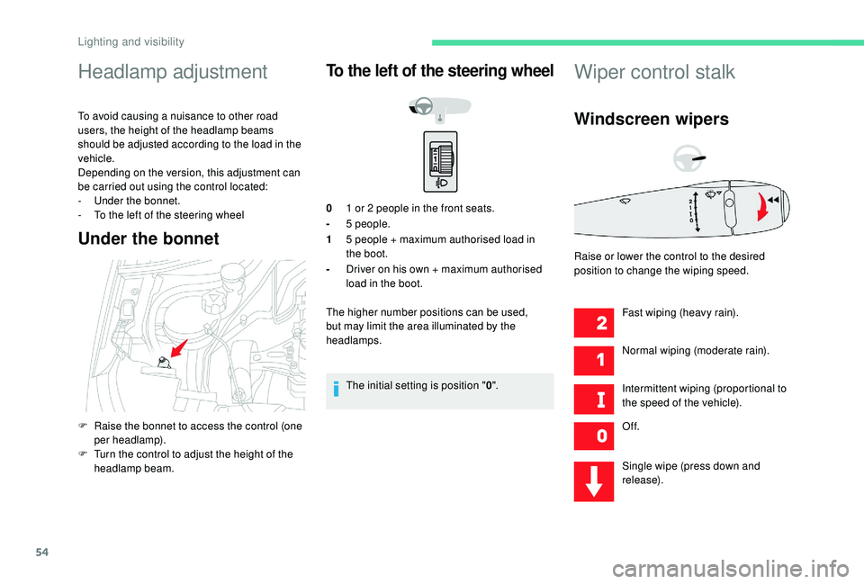
Headlamp adjustment
To avoid causing a nuisance to other road
users, the height of the headlamp beams
should be adjusted according to the load in the
vehicle.
Depending on the version, this adjustment can
be carried out using the control located:
-
U
nder the bonnet.
-
T
o the left of the steering wheel
Under the bonnet
To the left of the steering wheel
01 or 2 people in the front seats.
- 5
people.
1 5
people + maximum authorised load in
the boot.
- Driver on his own + maximum authorised
load in the boot.
The higher number positions can be used,
but may limit the area illuminated by the
headlamps.
The initial setting is position " 0".
Wiper control stalk
Windscreen wipers
Fast wiping (heavy rain).
Normal wiping (moderate rain).
Intermittent wiping (proportional to
the speed of the vehicle).
Of f.
Single wipe (press down and
release).
F
R
aise the bonnet to access the control (one
per headlamp).
F
T
urn the control to adjust the height of the
headlamp beam. Raise or lower the control to the desired
position to change the wiping speed.
Lighting and visibility
Page 62 of 260

60
If you purchased your vehicle outside the
Brand network, we invite you to check
the configuration of these ser vices and,
if desired, have a dealer change it to suit
your wishes. In a multilingual country,
configuration is possible in the official
national language of your choice.
For technical reasons and, in particular,
to improve the quality of the "telematic
services" services for customers, the
manufacturer reser ves the right to carry
out updates to the vehicle's on-board
communication system.Electronic stability control
(ESC)
A set of the following Electronic Stability
systems:
-
a
nti-lock braking system (ABS) and
electronic brake force distribution (EBFD),
-
em
ergency braking assistance (EBA),
-
w
heel anti-slip regulation (ASR) or traction
control,
-
d
ynamic stability control (DSC).
Definitions
Anti-lock braking system (ABS)
and electronic brake force
distribution (EBFD)
These systems improve the stability and
manoeuvrability of your vehicle when braking
and contribute towards improved control in
corners, in particular on poor or slippery road
surfaces.
The ABS prevents wheel lock in the event of
emergency braking.
The electronic brake force distribution system
manages the braking pressure wheel by wheel.
Emergency braking assistance
(EBA)
In an emergency, this system enables you to
reach the optimum braking pressure more
quickly and therefore reduce the stopping
distance.
Anti-slip regulation (ASR)
This system optimises traction in order to
avoid wheel slip by acting on the brakes of
the driving wheels and on the engine. It also
improves the directional stability of the vehicle
on acceleration.
Dynamic stability control (DSC)
If there is a difference between the path
followed by the vehicle and that required by the
driver, this system monitors each wheel and
automatically acts on the brake of one or more
wheels and on the engine to return the vehicle
to the required path, within the limits of the laws
of physics. It is triggered in relation to the speed at which
the brake pedal is pressed. This is felt by a
reduction in the resistance of the pedal and an
increase in braking efficiency.
Safety
Page 63 of 260

61
Anti-lock braking system
(ABS) and electronic brake
force distribution (EBFD)
The fixed illumination of this warning
lamp signals that there is a fault with
the ABS.
Illumination of this warning lamp,
coupled with the STOP and ABS
warning lamps, accompanied by
the display of a message and an
audible signal, signals that there is a
fault with the electronic brake force
distribution (EBFD).
Normal operation of the ABS may make
itself felt by slight vibration of the brake
pedal.
When braking in an emergency, press
firmly without ever releasing the
pressure. When changing wheels (tyres and rims),
ensure that these are approved for your
vehicle.Anti-slip regulation (ASR)
/ Dynamic stability control
(DSC)
Operation
These systems are activated automatically
every time the vehicle is started.
They come into operation in the event of a
problem of grip or trajectory.
Deactivation
In exceptional conditions (starting a vehicle
which is bogged down, stuck in snow, on soft
ground, etc.), it may be advisable to deactivate
these systems, so that the wheels can turn
freely and regain grip.
Reactivate the systems as soon as the level of
grip permits.
The vehicle retains conventional braking. Drive
carefully at moderate speed.
Contact a CITROËN dealer or a qualified
workshop as soon as possible.
You must stop as soon as it is safe to do so.
Call a CITROËN dealer or a qualified
workshop. This is indicated by this warning
lamp flashing in the instrument
panel.F
P
ress this button until the
corresponding symbol appears
in the instrument panel.
The button indicator lamp comes on.
The ASR and DSC systems will no longer have
an effect on engine operation or the brakes in
the event of an involuntary change of trajectory.
Reactivation
The ASR system is reactivated automatically
every time the ignition is switched back on or
from 30
mph (50 km/h).
Below 30
mph (50 km/h), you can reactivate it
manually.
F
P
ress this button again to
reactivate the system manually.
The button indicator lamp goes off.
5
Safety
Page 93 of 260

91
Under-inflation detection
System which automatically checks the
pressures of the tyres while driving.
The system monitors the pressure in all four
tyres, as soon as the vehicle is moving.
It compares the information given by the wheel
speed sensors with reference values, which
must be reinitialised ever y time the tyre
pressures are adjusted or a wheel changed.
The system triggers an alert as soon as it
detects a drop in the pressure of one or more
tyres.
The under-inflation detection system does
not replace the need for vigilance on the
part of the driver.
This system does not avoid the need to
check the tyre pressures (including the
spare wheel) every month as well as
before a long journey.
Driving with under-inflated tyres worsens
road-holding, lengthens braking distances,
causes premature wear of the tyres,
particularly in adverse conditions (heavy
loads, high speeds, long journeys). Driving with under-inflated tyres
increases fuel consumption.
The inflation pressures defined for your
vehicle can be found on the tyre pressure
label.
For more information on the
Identification markings , refer to the
corresponding section.
Checking tyre pressures
This check should be done when the tyres
are "cold" (vehicle stopped for 1
hour or
after a journey of less than 6
miles (10 km)
at moderate speeds).
Other wise, add 0.3
bar to the pressures
shown on the label.
Under-inflation alert
This warning is indicated by
continuous illumination of the
warning lamp, an audible signal and
a message displayed on the screen. F
R
educe speed immediately, avoid excessive
steering movements and sudden braking.
F
S
top as soon as it is safe to do so.
The loss of pressure detected does not
always cause visible bulging of the tyre.
Do not rely on a simple visual check.
F
I
f you have a compressor (such as the one
in the temporary puncture repair kit), check
the pressures of the four tyres when cold.
If it is not possible to carry out this check
immediately, drive carefully at reduced
speed.
or
F
I
n the event of a puncture, use the
temporary puncture repair kit or the spare
wheel (depending on equipment).
The warning remains active until the
system is reinitialised.Reinitialisation
The system must be reinitialised after any
adjustment to the pressures of one or more
tyres, and after changing one or more wheels.
6
Driving
Page 96 of 260

94
Programming
You do not have to switch the speed limiter on
in order to set the speed.
F
T
urn thumb wheel 1 to the "LIMIT" position:
the speed limiter mode is selected but is not
switched on (PAUSE).
F
S
et the speed value by pressing button 2 or
3
(e.g. 55 mph (90 km/h)).
You can change the programmed speed further
using buttons 2
and 3:
-
B
y +/- 1 mph (1 km/h) = short press.
-
B
y +/- 5 mph (5 km/h) = long press.
-
I
n steps of +/- 5 mph (5 km/h) = press and
hold.
F
S
witch the speed limiter on by pressing
button 4 .
Pause
F Switch the speed limiter off by pressing
button 4: a message on the screen confirms
the stop (PAUSE).
F
S
witch the speed limiter back on by
pressing button 4
again.
Temporarily exceeding the
programmed speed
Pressing the accelerator pedal in order to
exceed the programmed speed will have
no effect unless you press the pedal firmly
beyond the point of resistance .
The speed limiter is deactivated temporarily
and the programmed speed, which is still
displayed, flashes, accompanied by an audible
signal. Returning to the programmed speed, by means
of intentional or unintentional deceleration of
the vehicle, automatically cancels the flashing
of the programmed speed and the audible
signal stops.
Exiting the limiter mode
F Turn thumb wheel 1
to the 0 position:
the speed limiter mode is deselected.
The display returns to the total distance
recorder.
Operating fault
In the event of a speed limiter fault, the speed
is cleared resulting in flashing of the dashes.
Have it checked by a CITROËN dealer or a
qualified workshop.
Driving
Page 98 of 260

96
5Cruise control off/resume indication.
6 Cruise control selection indication.
7 Programmed speed value.
Programming
F Turn thumb wheel 1 to the "CRUISE"
position: the cruise control mode is selected
but is not switched on (PAUSE).
F
S
et the programmed speed by
accelerating to the required
speed, then press button 2
or 3
(e.g. 65 mph (110 km/h)).
Pause
F Switch off the cruise control by pressing button 4: a confirmation message appears
on the screen (PAUSE).
You can change the programmed speed further
using buttons 2
and 3
:
-
B
y +/- 1 mph (1 km/h) = short press.
-
B
y +/- 5 mph (5 km/h) = long press.
-
I
n steps of +/- 5 mph (5 km/h) = press and
hold. F
S
witch the cruise control back on by
pressing button 4 again.
Exceeding the programmed
speed
Intentional or unintentional exceeding of the
programmed speed results in flashing of this
speed on the display.
Returning to the programmed speed, by means
of intentional or unintentional deceleration of
the vehicle, automatically cancels the flashing
of the programmed speed.
Leaving cruise control
mode
F Turn thumb wheel 1
to the 0 position:
the cruise control mode is deselected.
The display returns to the total distance
recorder.
Displays on the instrument panel
The programmed information is grouped
together in the instrument panel screen.
Driving
Page 124 of 260

122
Spare wheel
Procedure for changing a damaged wheel with
the spare wheel using the tools provided with
the vehicle.
Access to tooling
List of tools
1Wheelbrace.
For removing the hub cap and removing
the wheel bolts.
2 Jack with integrated crank.
Used to raise the vehicle.
3 Wheel bolt cover removal tool.
Removes the wheel bolt covers on alloy
wheels.
4 Towing eye.
For more information on Towing the vehicle ,
refer to the corresponding section. All of these tools are specific to your
vehicle and may vary according to the
level of equipment.
Do not use them for any other purposes.
The jack must only be used to change a
wheel with a damaged or punctured tyre.
Do not use any jack other than the one
supplied with this vehicle.
If the vehicle does not have its original jack,
contact a CITROËN dealer or a qualified
workshop to obtain the correct jack for it.
The jack meets European standards,
as defined in the Machinery Directive
2006/42/EC.
The jack does not require any
maintenance.
The tools are installed in the boot under the
f l o o r.
F
O
pen the boot.
F
L
ift the floor and remove it.
F
R
emove the storage box containing the
tools. These tools are specific to your vehicle and
may vary according to the equipment. Do not
use them for purposes other than those listed
below.
In the event of a breakdown
Page 126 of 260

124
Removing a wheel
Parking the vehicle
* Position P for the automatic gearbox
Park the vehicle where it does not block
traffic: the ground must be level, stable
and non-slippery.
Apply the parking brake, switch off the
ignition and engage first gear* so as to
block the wheels.
Check that the parking brake warning
lamp comes on fixed in the instrument
panel.
The occupants must get out of the vehicle
and wait where they are safe.
Make sure that the jack is correctly
positioned at one of the vehicle's jacking
points.
Incorrect use of the jack could cause the
vehicle to collapse.
Never go underneath a vehicle raised
using a jack; use an axle stand.
Do not use a jack other than the one
supplied by the manufacturer.
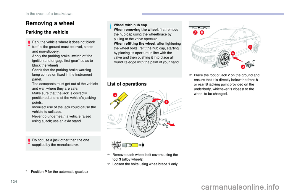
Wheel with hub cap
When removing the wheel
, first remove
the hub cap using the wheelbrace by
pulling at the valve aperture.
When refitting the wheel , after tightening
the wheel bolts, refit the hub cap, starting
by placing its aperture in line with the
valve and then pushing it into place all
round its edge with the palm of your hand.
List of operations
F Remove each wheel bolt covers using the tool 3 (alloy wheels).
F
L
oosen the bolts using wheelbrace 1 o n l y.F
P
lace the foot of jack 2 on the ground and
ensure that it is directly below the front A
or rear B jacking point provided on the
underbody, whichever is closest to the
wheel to be changed.
In the event of a breakdown