instrument panel CITROEN C-ZERO 2017 Handbook (in English)
[x] Cancel search | Manufacturer: CITROEN, Model Year: 2017, Model line: C-ZERO, Model: CITROEN C-ZERO 2017Pages: 174, PDF Size: 4.15 MB
Page 4 of 174
.
.
Instrument panel 10
Indicator and warning lamps
1
1
Main battery state of charge indicator
1
9
Energy consumption / generation indicator
2
0
Distance recorder
2
1
Trip distance recorder
2
1
Lighting dimmer
2
2
Service indicator
2
2
Range indicator
2
4Remote control key
2
5
Doors
2
8
Boot
2
9
Electric windows
3
0
Charging flaps
3
1
Front seats 3 2
Rear seats
3
4
Mirrors
36
I
nterior fittings
3
8
Ventilation
4
1
Heating
4
3
Air conditioning
4
3
Front demist - defrost
4
6
Rear screen demist - defrost
4
6
Remote control
4
7Lighting controls
5
3
Automatic illumination of headlamps
5
5
Headlamp adjustment
5
6
Wiper control
5
6
Courtesy lamp
5
7
General safety recommendations 5 8
Hazard warning lamps
5
9
Automatic operation of brake lamps
5
9
Horn
5
9
Pedestrian horn
6
0
Emergency or assistance
6
1
Braking assistance systems
6
3
Trajectory control systems
6
5
Engine brake reduction indicator lamp
6
6
Front seat belts
6
7
Airbags
7
0
Child seats
7
4
Deactivating the passenger front airbag
7
7
ISOFIX child seats
8
3
Child lock
8
6
Over view
Eco-driving
Instruments Access
Ease of use and comfort Lighting and visibility
Safety
Contents
Page 9 of 174
7
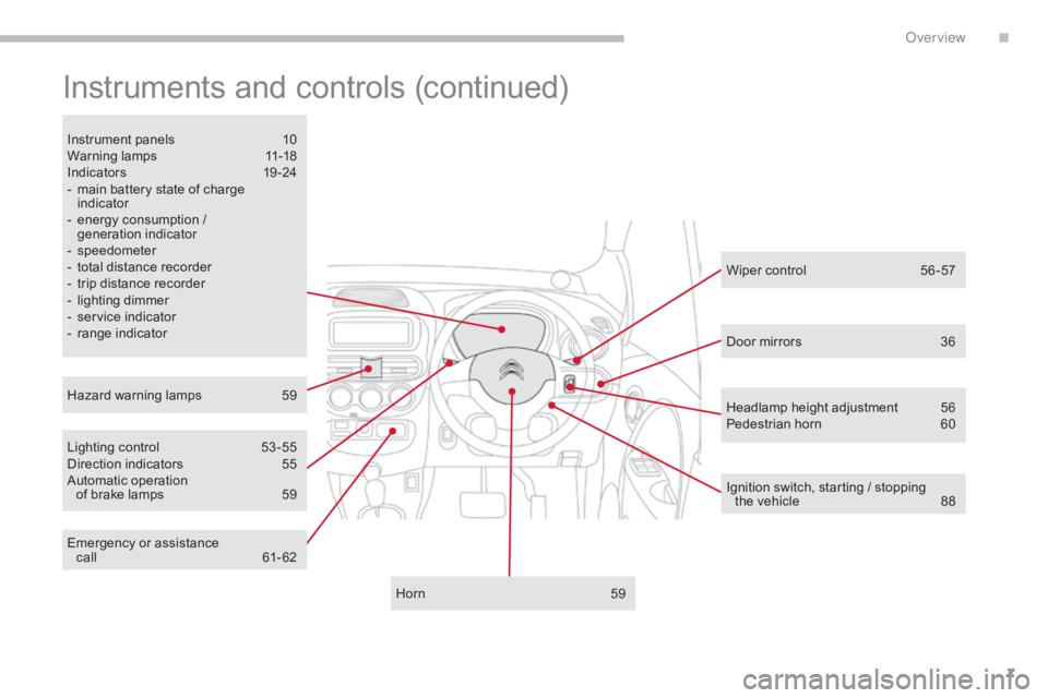
Instruments and controls (continued)
Lighting control 53 -55
Direction indicators 5 5
Automatic operation
of brake lamps
5
9
Instrument panels
1
0
Warning lamps
1
1-18
Indicators
19
-24
-
m
ain battery state of charge
indicator
-
e
nergy consumption /
generation indicator
-
s
peedometer
-
t
otal distance recorder
-
t
rip distance recorder
-
l
ighting dimmer
-
s
ervice indicator
-
r
ange indicator
Horn
5
9
Hazard warning lamps
5
9 Wiper control
5
6 -57
Ignition switch, starting / stopping the
vehicle
8
8
Door mirrors
3
6
Emergency or assistance call
61
- 62 Headlamp height adjustment
5
6
Pedestrian horn
6
0
.
Over view
Page 12 of 174
10
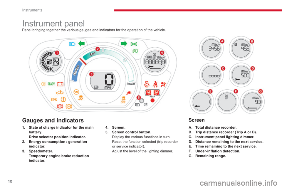
Instrument panelPanel bringing together the various gauges and indicators for the operation of the vehicle.
1.
S
tate of charge indicator for the main
battery.
D
rive selector position indicator.
2.
E
nergy consumption / generation
indicator.
3.
S
peedometer.
T
emporary engine brake reduction
indicator. A.
T
otal distance recorder.
B.
T
rip distance recorder (Trip A or B).
C.
I
nstrument panel lighting dimmer.
D.
D
istance remaining to the next service.
E.
T
ime remaining to the next ser vice.
F.
U
nder-inflation detection.
G.
R
emaining range.
4.
S
creen.
5.
S
creen control button.
D
isplay the various functions in turn.
R
eset the function selected (trip recorder
or service indicator).
A
djust the level of the lighting dimmer.
Gauges and indicatorsScreen
Instruments
Page 14 of 174

12
Operation indicator lamps
Warning / indicator lamp State Cause Action / Observations
Left-hand
direction
indicato r Flashing with audible
signal.
The lighting stalk is pushed down.
Right-hand
direction
indicator Flashing with audible
signal.
The lighting stalk is pushed up.
Hazard warning
lamps Flashing with audible
signal. The hazard warning lamps switch,
located on the dashboard, has been
operated. The left-hand and right-hand direction indicators and
their associated indicator lamps flash simultaneously.
Sidelamps and/
or dipped beam
headlamps On fixed.
The sidelamps and/or dipped beam
headlamps are on.
Front foglamps On fixed. The front foglamps are switched on. Turn the ring on the stalk rear wards twice to switch off
the front foglamps.
Rear foglamp On fixed. The rear foglamp is switched on. Turn the ring on the stalk rear wards to switch off the
rear foglamp.
Main beam
headlamps
On fixed.
The lighting stalk is pulled towards you. Pull the stalk to return to dipped beam headlamps.
If one of the following indicator lamps comes on in the instrument panel, this confirms that the corresponding system has come into operation.
Instruments
Page 21 of 174
19
Main battery state of charge indicator
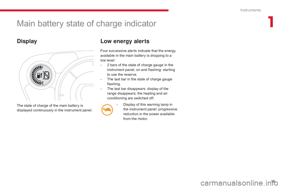
Display
Four successive alerts indicate that the energy
available in the main battery is dropping to a
low level:
-
2 b
ars of the state of charge gauge in the
instrument panel, on and flashing: starting
to use the reserve.
-
T
he last bar in the state of charge gauge
flashing.
-
T
he last bar disappears: display of the
range disappears; the heating and air
conditioning are switched off.
Low energy alerts
- Display of this warning lamp in the instrument panel: progressive
reduction in the power available
from the motor.
The state of charge of the main battery is
displayed continuously in the instrument panel.
1
Instruments
Page 23 of 174

21
Instrument panel screenWhen the ignition switch is in the "ON" position, press button A repeatedly to display the following information in turn.
Distance recorder
System for measuring the total distance
travelled by the vehicle during its life.
Press button A .
The total distance appears in the screen.Reset to zero
With the ignition on and either trip A or B
displayed, press the button for more than
2
seconds.
Trip distance recorder (Trip A or B)
Each of these trip recorders indicates the
distance travelled since the last reset.
Press button A to display the desired trip.
Changing the speedometer units
With the total distance recorder displayed,
press and hold button A for a few seconds to
change the speedometer units (mph or km/h).
The range indicator is displayed in the units
(miles or km) corresponding to those of the
speedometer (mph or km/h).
1
Instruments
Page 26 of 174
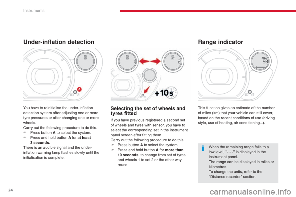
24
This function gives an estimate of the number
of miles (km) that your vehicle can still cover,
based on the recent conditions of use (driving
style, use of heating, air conditioning...).
Range indicator
When the remaining range falls to a
low level, "- - -" is displayed in the
instrument panel.
The range can be displayed in miles or
kilometres.
To change the units, refer to the
"Distance recorder" section.
Under-inflation detection
Selecting the set of wheels and
tyres fitted
If you have previous registered a second set
of wheels and tyres with sensor, you have to
select the corresponding set in the instrument
panel screen after fitting them.
Carry out the following procedure to do this.
F
P
ress button A to select the system.
F
P
ress and hold button A for more than
10
seconds , to change from set of tyres
and wheels 1 to set 2 or the other way
round.
You have to reinitialise the under-inflation
detection system after adjusting one or more
tyre pressures or after changing one or more
wheels.
Carry out the following procedure to do this.
F
P
ress button A to select the system.
F
P
ress and hold button A for at least
3
seconds .
There is an audible signal and the under-
inflation warning lamp flashes slowly until the
initialisation is complete.
Instruments
Page 30 of 174
28
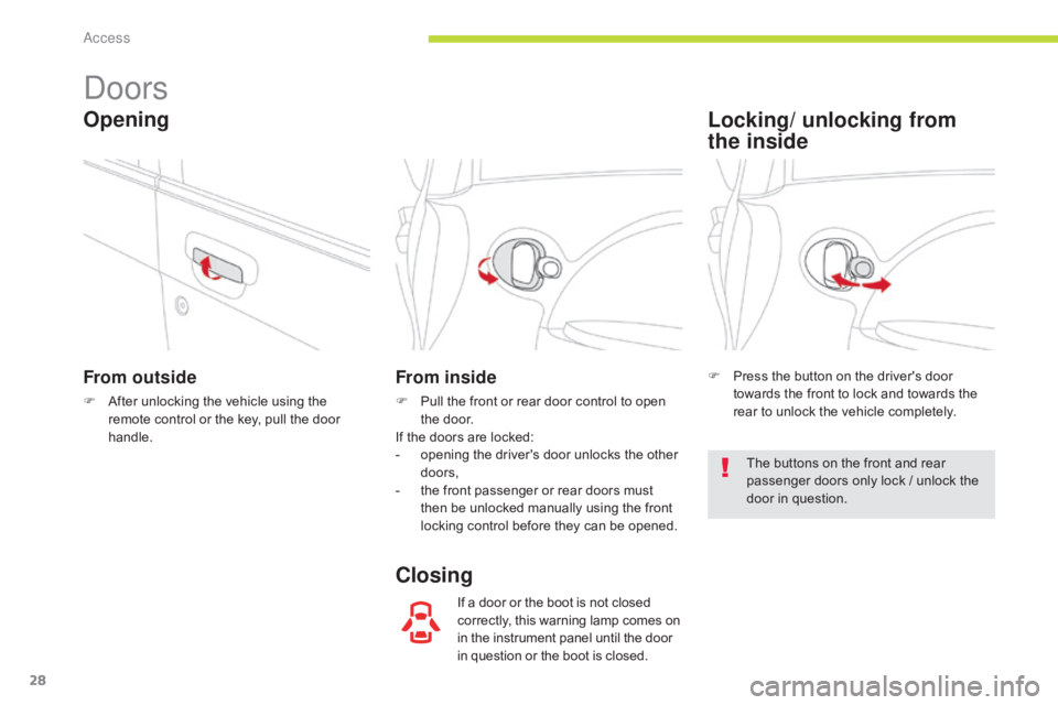
Doors
From outside
F After unlocking the vehicle using the remote control or the key, pull the door
handle.
From inside
F Pull the front or rear door control to open the door.
If the doors are locked:
-
o
pening the driver's door unlocks the other
doors,
-
t
he front passenger or rear doors must
then be unlocked manually using the front
locking control before they can be opened.
If a door or the boot is not closed
correctly, this warning lamp comes on
in the instrument panel until the door
in question or the boot is closed.
Opening
ClosingLocking/ unlocking from
the
inside
F Press the button on the driver's door
towards the front to lock and towards the
rear to unlock the vehicle completely.
The buttons on the front and rear
passenger doors only lock / unlock the
door in question.
Access
Page 55 of 174
53
Lighting controls
Main lighting
The various front and rear lamps of the vehicle
are designed to adapt the lighting progressively
in relation to the climatic conditions and so
ensure the best visibility for the driver:
-
s
idelamps, to be seen,
-
d
ipped beam headlamps to see without
dazzling other drivers,
-
m
ain beam headlamps to see clearly when
the road is clear.
Additional lighting
Other lamps are provided to fulfil the
requirements of particular driving conditions:
-
a r
ear foglamp to be seen from a distance,
-
f
ront foglamps for even better visibility,
-
d
aytime running lamps to be seen during
the day.
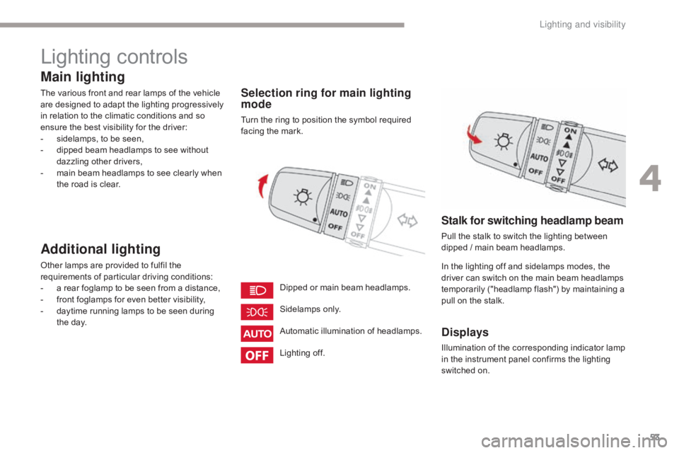
Selection ring for main lighting
mode
Turn the ring to position the symbol required
facing the mark.
Automatic illumination of headlamps. Sidelamps only.
Dipped or main beam headlamps.
Stalk for switching headlamp beam
Pull the stalk to switch the lighting between
dipped / main beam headlamps.
In the lighting off and sidelamps modes, the
driver can switch on the main beam headlamps
temporarily ("headlamp flash") by maintaining a
pull on the stalk.
Displays
Illumination of the corresponding indicator lamp
in the instrument panel confirms the lighting
switched on.
Lighting off.
4
Lighting and visibility
Page 67 of 174

65
Anti-slip regulation (ASR)
and electronic stability
programme (ESP)
Trajectory control systems
Deactivation
In exceptional conditions (starting a vehicle
which is bogged down, stuck in snow, on soft
ground, ...), it may be advisable to deactivate
the ASR and ESP systems to regain grip.
F
P
ress this button button, located on the
dashboard to the right of the steering
wheel, until the corresponding symbol
appears in the instrument panel screen.
Activation
These systems are activated automatically
each time the vehicle is started.
They come into operation in the event of a grip
or trajectory problem. The display of this symbol indicates
that the ASR and ESP systems are
deactivated.
Reactivation
These systems are not reactivated
automatically.
F
P
ress this button again to reactivate them
manually.
The symbol going off in the instrument panel
indicates the reactivation of the ASR and ESP
systems.
The anti-slip regulation (also known as Traction
Control) optimises traction to limit wheel spin,
by acting on the brakes of the driving wheels
and on the engine.
The electronic stability programme acts on the
brake of one or more wheels and on the engine
to keep the vehicle on the trajectory required
by the driver, within the limits of the laws of
physics.
This is indicated by flashing of this
symbol in the instrument panel. The ASR /ESP systems offer should not
encourage the driver to take extra risks
or drive at high speed.
The correct functioning of these
systems depends on observation of
the manufacturer's recommendations
regarding the wheels (tyres and rims),
the braking components, the electronic
components and the assembly
and repair procedures used by the
CITROËN dealer network.
After an impact, have these systems
checked by a CITROËN dealer or a
qualified workshop.
Operating fault
The display of this message
in the instrument panel
indicates a malfunction of
these systems.
Contact a CITROËN dealer or a qualified
workshop to have the ASR /ESP systems
checked.
Excessive wheel spin may damage your
vehicle's differential.
5
Safety