boot Citroen C3 2014 2.G User Guide
[x] Cancel search | Manufacturer: CITROEN, Model Year: 2014, Model line: C3, Model: Citroen C3 2014 2.GPages: 284, PDF Size: 9.01 MB
Page 63 of 284
61
C3_en_Chap04_ouvertures_ed01-2014
Emergency control
Locking the driver's door
F Insert the key in the lock, then turn it to
the right.
Unlocking the driver's door
F Insert the key in the lock, then turn it to the left.
Locking the front and rear
passenger doors
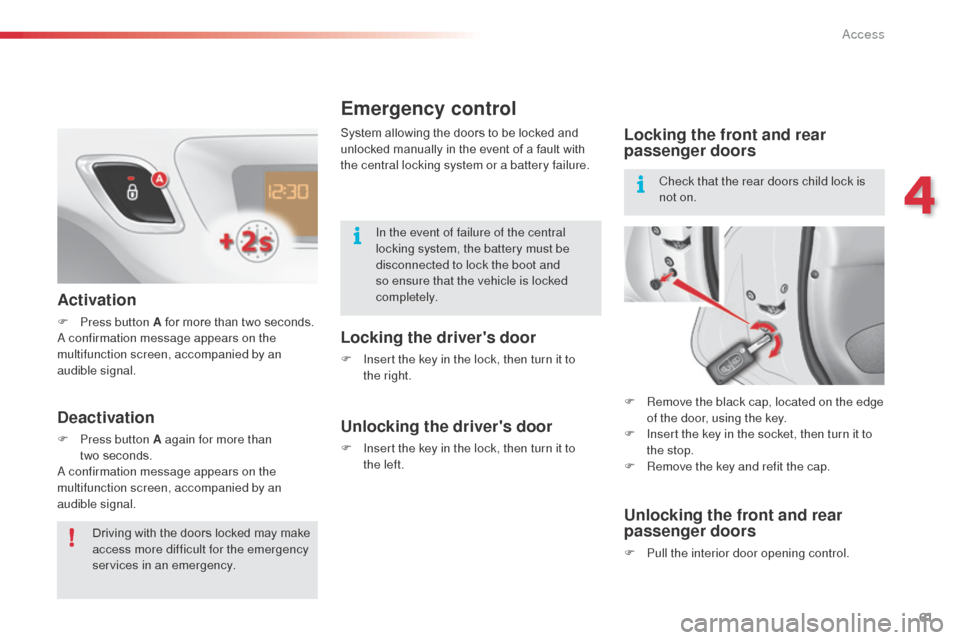
F Remove the black cap, located on the edge of the door, using the key.
F
I
nsert the key in the socket, then turn it to
the stop.
F
R
emove the key and refit the cap.
Unlocking the front and rear
passenger doors
F Pull the interior door opening control.
In the event of failure of the central
locking system, the battery must be
disconnected to lock the boot and
so ensure that the vehicle is locked
completely.
Check that the rear doors child lock is
not on.
System allowing the doors to be locked and
unlocked manually in the event of a fault with
the central locking system or a battery failure.
Activation
F Press button A for more than two seconds.a
confirmation message appears on the
multifunction screen, accompanied by an
audible signal.
Deactivation
F Press button A again for more than two seconds.
a
confirmation message appears on the
multifunction screen, accompanied by an
audible signal.
Driving with the doors locked may make
access more difficult for the emergency
services in an emergency.
4
access
Page 64 of 284
62
C3_en_Chap04_ouvertures_ed01-2014
boot
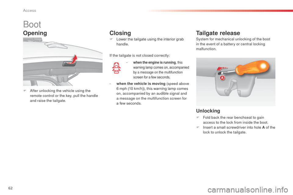
F after unlocking the vehicle using the
remote control or the key, pull the handle
and raise the tailgate. F
L
ower the tailgate using the interior grab
handle.
-
when the engine is running
, this
warning lamp comes on, accompanied
by a message on the multifunction
screen for a few seconds,
Tailgate release
Unlocking
F Fold back the rear benchseat to gain access to the lock from inside the boot.
F
I
nsert a small screwdriver into hole A of the
lock to unlock the tailgate.
If the tailgate is not closed correctly:
Opening
Closing
- when the vehicle is moving (speed above
6 mph (10 km/h)), this warning lamp comes
on, accompanied by an audible signal and
a message on the multifunction screen for
a few seconds. System for mechanical unlocking of the boot
in the event of a battery or central locking
malfunction.
access
Page 72 of 284
70
C3_en_Chap05_Visibilite_ed01-2014
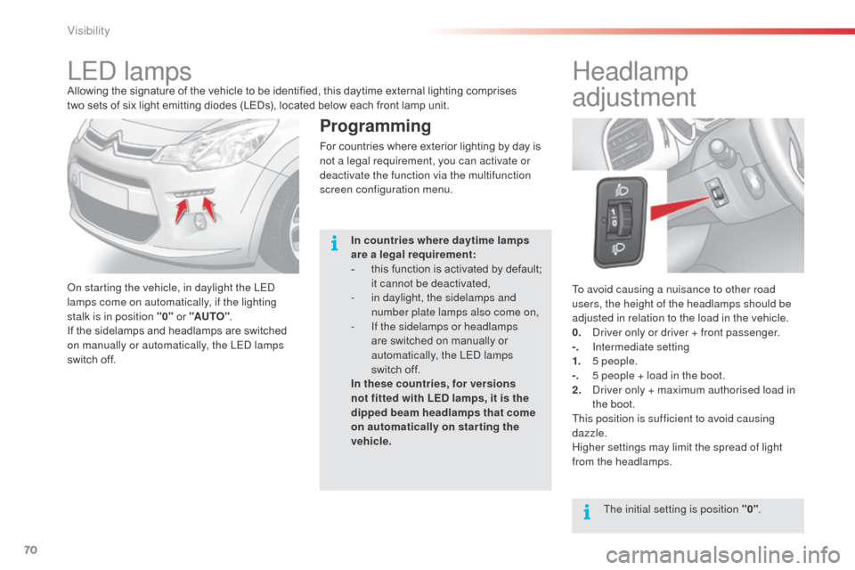
To avoid causing a nuisance to other road
users, the height of the headlamps should be
adjusted in relation to the load in the vehicle.
0. d
r
iver only or driver + front passenger.
-.
I
ntermediate setting
1.
5
people.
-.
5 p
eople + load in the boot.
2.
d
r
iver only + maximum authorised load in
the boot.
This position is sufficient to avoid causing
dazzle.
Higher settings may limit the spread of light
from the headlamps.
Headlamp
adjustment
The initial setting is position "0" .
LEd lampsAllowing the signature of the vehicle to be identified, this daytime external lighting comprises
two
sets of six light emitting diodes (LEDs), located below each front lamp unit.
on s
tarting the vehicle, in daylight the LE
d
lamps come on automatically, if the lighting
stalk is in position "0" or "AUTO".
If the sidelamps and headlamps are switched
on manually or automatically, the LE
d
lamps
switch off.
Programming
For countries where exterior lighting by day is
not a legal requirement, you can activate or
deactivate the function via the multifunction
screen configuration menu.
In countries where daytime lamps
are a legal requirement:
-
t
his function is activated by default;
it cannot be deactivated,
-
i
n daylight, the sidelamps and
number plate lamps also come on,
-
I
f the sidelamps or headlamps
are switched on manually or
automatically, the LE
d
lamps
switch off.
In these countries, for versions
not fitted with LED lamps, it is the
dipped beam headlamps that come
on automatically on starting the
vehicle.
Visibility
Page 77 of 284
75
C3_en_Chap05_Visibilite_ed01-2014
Interior mood lighting
Switching on
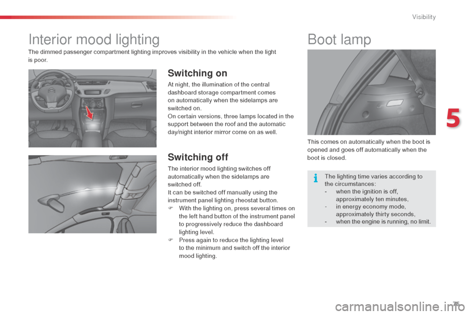
at night, the illumination of the central
dashboard storage compartment comes
on automatically when the sidelamps are
switched on.
on c
ertain versions, three lamps located in the
support between the roof and the automatic
day/night interior mirror come on as well.
Switching off
The interior mood lighting switches off
automatically when the sidelamps are
switched
off.
It can be switched off manually using the
instrument panel lighting rheostat button.
F
W
ith the lighting on, press several times on
the left hand button of the instrument panel
to progressively reduce the dashboard
lighting level.
F
P
ress again to reduce the lighting level
to the minimum and switch off the interior
mood lighting. This comes on automatically when the boot is
opened and goes off automatically when the
boot is closed.
boot lamp
The dimmed passenger compartment lighting improves visibility in the vehicle when the light
i s
p o o r.
The lighting time varies according to
the
circumstances:
-
w
hen the ignition is off,
approximately ten minutes,
-
i
n energy economy mode,
approximately thirty seconds,
-
w
hen the engine is running, no limit.
5
Visibility
Page 83 of 284
81
C3_en_Chap06_amenagement_ed01-2014
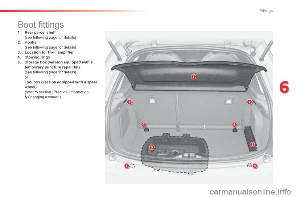
Boot fittings
1. Rear parcel shelf (
see following page for details)
2.
Hoo
ks
(
see following page for details)
3.
L
ocation for Hi-Fi amplifier
4.
S
towing rings
5.
S
torage box (version equipped with a
temporary puncture repair kit)
(
see following page for details)
or
T
ool box (version equipped with a spare
wheel)
(
refer to section "Practical Information -
§ Changing a wheel")
6
Fittings
Page 84 of 284

82
C3_en_Chap06_amenagement_ed01-2014
Rear parcel shelf
To remove the shelf:
F
u nhook the two cords,
F
r
aise the shelf slightly, then unclip it on
each side.
Hooks
The hooks can be used to hold shopping bags.
Storage box
F Raise the boot carpet by pulling the strap upwards to gain access to the storage box.
This has areas for storing a temporary puncture
repair kit, a box of spare bulbs, a first aid kit,
two warning triangles, ...
F
r
efit the boot floor carpet by folding it
slightly in the middle.
Fittings
Page 143 of 284
141
C3_en_Chap11_Info-pratiques_ed01-2014
Temporary puncture repair kit
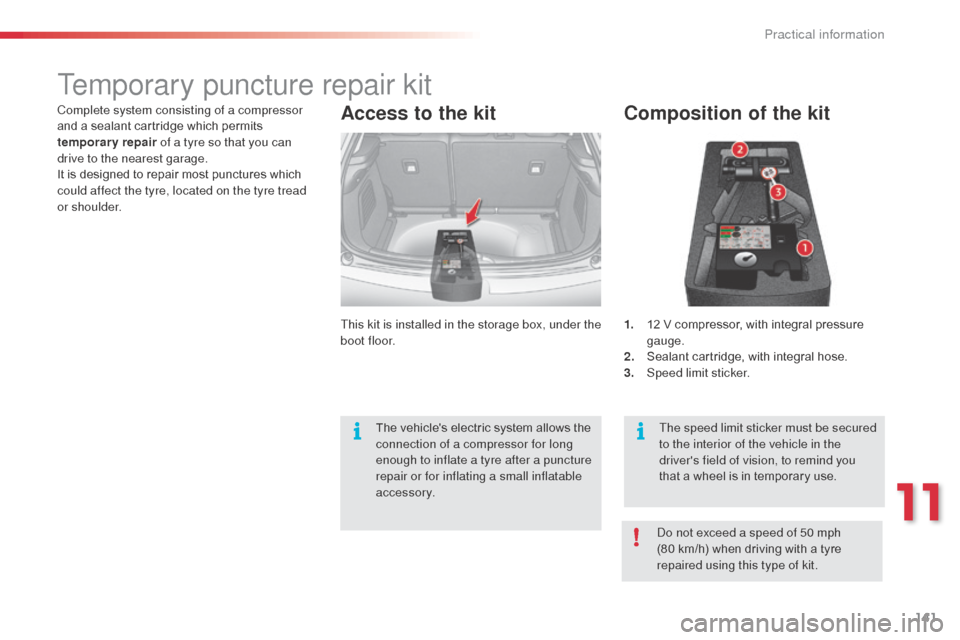
Composition of the kit
1. 12 V compressor, with integral pressure gauge.
2.
S
ealant cartridge, with integral hose.
3.
Spe
ed limit sticker.
Access to the kit
This kit is installed in the storage box, under the
boot floor.
The speed limit sticker must be secured
to the interior of the vehicle in the
driver's field of vision, to remind you
that a wheel is in temporary use.
Complete system consisting of a compressor
and a sealant cartridge which permits
temporary repair
of a tyre so that you can
drive to the nearest garage.
It is designed to repair most punctures which
could affect the tyre, located on the tyre tread
or shoulder.
do n
ot exceed a speed of 50 mph
(80
km/h) when driving with a tyre
repaired using this type of kit.
The vehicle's electric system allows the
connection of a compressor for long
enough to inflate a tyre after a puncture
repair or for inflating a small inflatable
accessory.
11
Practical information
Page 148 of 284
146
C3_en_Chap11_Info-pratiques_ed01-2014
Changing a wheel
The tools are installed in the boot under the
f l o o r.
To gain access to them:
F
o
pen the boot,
F
r
aise the floor,
F
r
emove the polystyrene storage box,
F
u
nclip and remove the box containing the
tools.
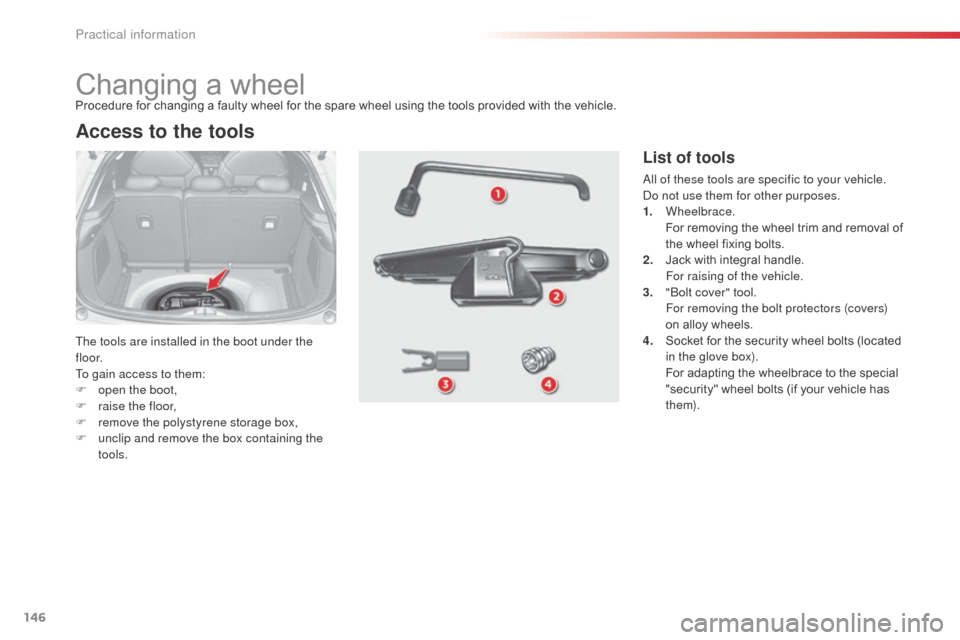
Access to the tools
Procedure for changing a faulty wheel for the spare wheel using the tools provided with the vehicle.
List of tools
all of these tools are specific to your vehicle. do n ot use them for other purposes.
1.
Wheelbrace.
F
or removing the wheel trim and removal of
the wheel fixing bolts.
2.
J
ack with integral handle.
F
or raising of the vehicle.
3.
"bo
lt cover" tool.
F
or removing the bolt protectors (covers)
on alloy wheels.
4.
S
ocket for the security wheel bolts (located
in the glove box).
F
or adapting the wheelbrace to the special
"security" wheel bolts (if your vehicle has
them).
Practical information
Page 149 of 284
147
C3_en_Chap11_Info-pratiques_ed01-2014
Wheel with trim
When removing the wheel, first
detach the trim using the wheelbrace 1
pulling at the valve passage hole.
When refitting the wheel , refit the
trim starting by placing its cut-out at the
valve and press around its edge with
the palm of your hand.
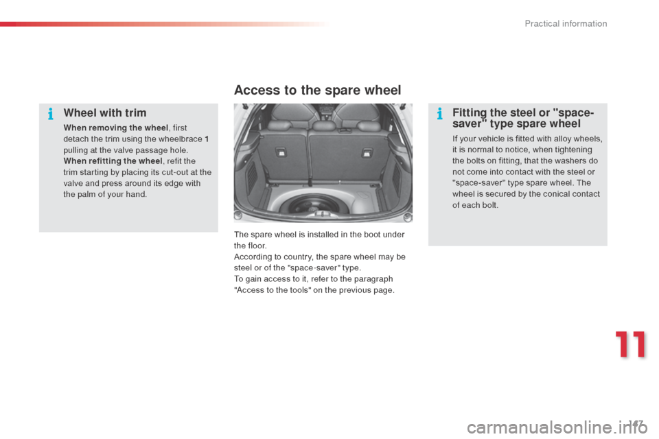
Access to the spare wheel
The spare wheel is installed in the boot under
t h e f l o o r.
According to country, the spare wheel may be
steel or of the "space-saver" type.
To gain access to it, refer to the paragraph
"
ac
cess to the tools" on the previous page.
Fitting the steel or "space-
saver" type spare wheel
If your vehicle is fitted with alloy wheels,
it is normal to notice, when tightening
the bolts on fitting, that the washers do
not come into contact with the steel or
"space-saver" type spare wheel. The
wheel is secured by the conical contact
of each bolt.
11
Practical information
Page 150 of 284
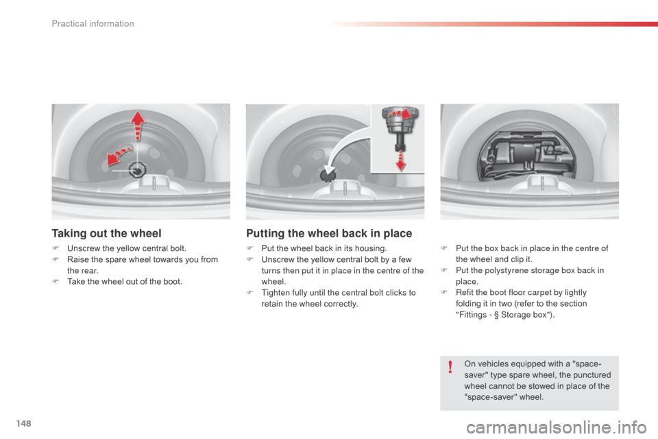
148
C3_en_Chap11_Info-pratiques_ed01-2014
Taking out the wheel
F Unscrew the yellow central bolt.
F R aise the spare wheel towards you from
the rear.
F
T
ake the wheel out of the boot.
Putting the wheel back in place
F Put the wheel back in its housing.
F U nscrew the yellow central bolt by a few
turns then put it in place in the centre of the
wheel.
F
T
ighten fully until the central bolt clicks to
retain the wheel correctly. F
P ut the box back in place in the centre of
the wheel and clip it.
F
P
ut the polystyrene storage box back in
place.
F
R
efit the boot floor carpet by lightly
folding it in two (refer to the section
"Fittings
- § Storage box").
On vehicles equipped with a "space-
saver" type spare wheel, the punctured
wheel cannot be stowed in place of the
"space-saver" wheel.
Practical information