wheel Citroen C4 2005 2.G Owners Manual
[x] Cancel search | Manufacturer: CITROEN, Model Year: 2005, Model line: C4, Model: Citroen C4 2005 2.GPages: 462, PDF Size: 10.48 MB
Page 380 of 462
Downloaded from www.Manualslib.com manuals search engine AXLES
SUSPENSION
STEERING
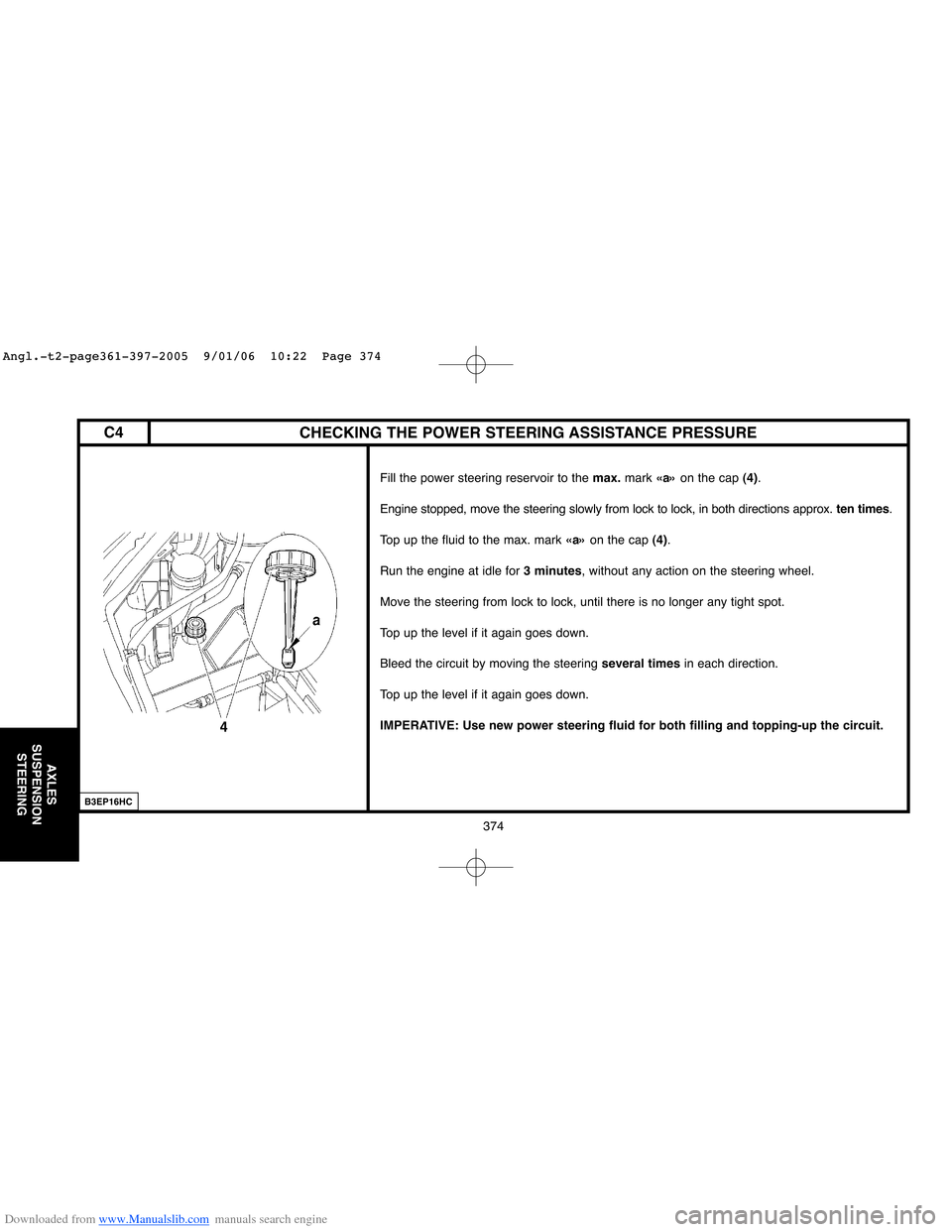
CHECKING THE POWER STEERING ASSISTANCE PRESSURE
Fill the power steering reservoir to the max.mark «a»on the cap (4).
Engine stopped, move the steering slowly from lock to lock, in both directions approx. ten times.
Top up the fluid to the max. mark «a»on the cap (4).
Run the engine at idle for 3 minutes, without any action on the steering wheel.
Move the steering from lock to lock, until there is no longer any tight spot.
Top up the level if it again goes down.
Bleed the circuit by moving the steering several timesin each direction.
Top up the level if it again goes down.
IMPERATIVE: Use new power steering fluid for both filling and topping-up the circuit.
B3EP16HC
374
C4
Angl.-t2-page361-397-2005 9/01/06 10:22 Page 374
Page 381 of 462
Downloaded from www.Manualslib.com manuals search engine 375
AXLES
SUSPENSION
STEERING
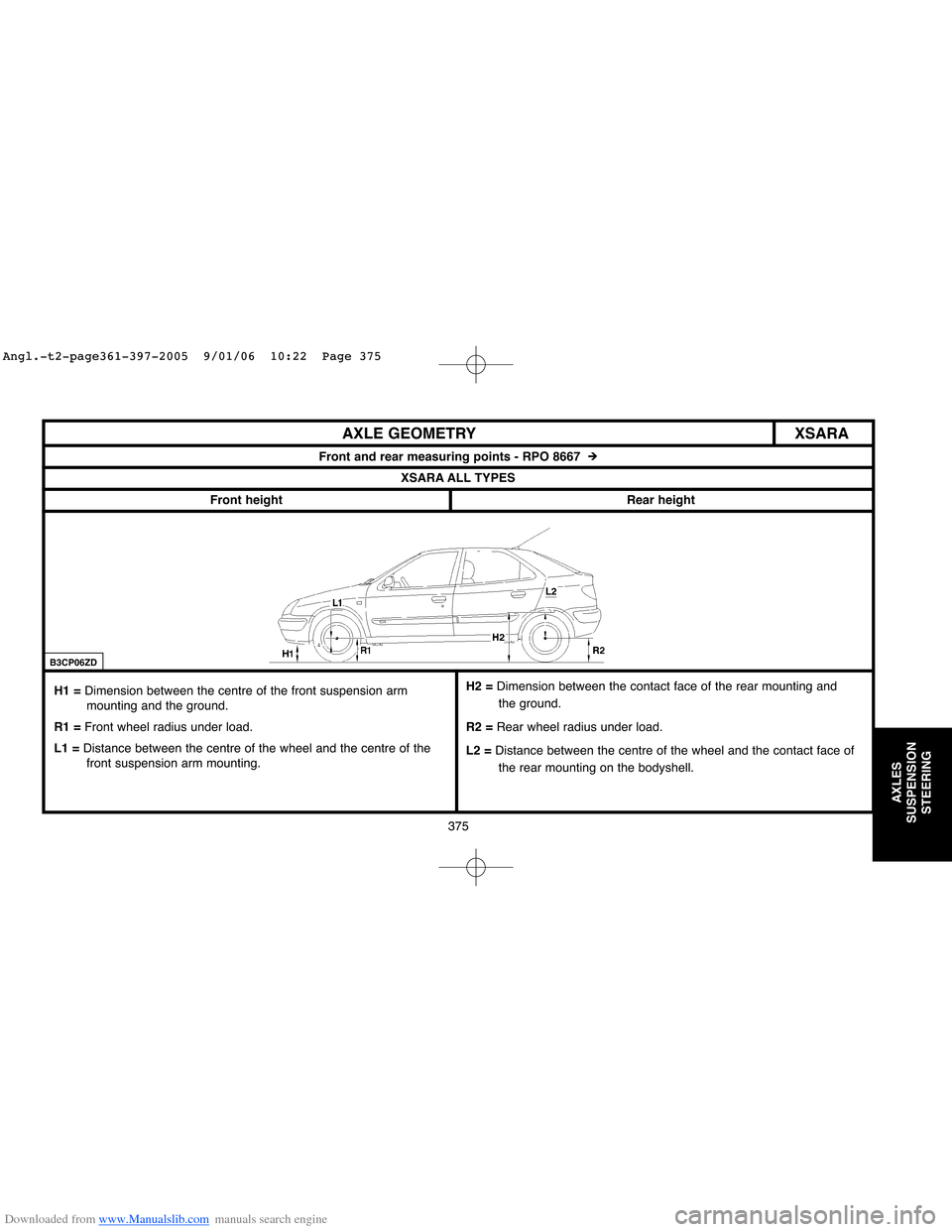
XSARA AXLE GEOMETRY
Front and rear measuring points - RPO 8667 #
XSARA ALL TYPES
Front height
Rear height
H1 = Dimension between the centre of the front suspension arm
mounting and the ground.
R1 =Front wheel radius under load.
L1 =Distance between the centre of the wheel and the centre of the
front suspension arm mounting.
B3CP06ZD
H2 = Dimension between the contact face of the rear mounting and
the ground.
R2 =Rear wheel radius under load.
L2 =Distance between the centre of the wheel and the contact face of
the rear mounting on the bodyshell.
Angl.-t2-page361-397-2005 9/01/06 10:22 Page 375
Page 382 of 462
Downloaded from www.Manualslib.com manuals search engine 376
AXLES
SUSPENSION
STEERING
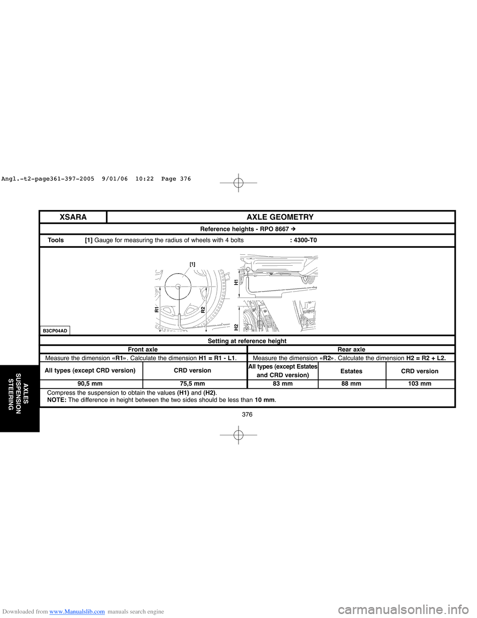
Setting at reference height
Front axle Rear axle
Measure the dimension «R1». Calculate the dimension H1 = R1 - L1. Measure the dimension «R2». Calculate the dimension H2 = R2 + L2.
All types (except CRD version) CRD versionAll types (except Estates
and CRD version) Estates CRD version
90,5 mm 75,5 mm 83 mm 88 mm 103 mm
Compress the suspension to obtain the values (H1)and (H2).
NOTE:The difference in height between the two sides should be less than 10 mm.
AXLE GEOMETRY
Reference heights - RPO 8667 #
Tools [1] Gauge for measuring the radius of wheels with 4 bolts: 4300-T0
XSARA
B3CP04AD
Angl.-t2-page361-397-2005 9/01/06 10:22 Page 376
Page 386 of 462
Downloaded from www.Manualslib.com manuals search engine 380
AXLES
SUSPENSION
STEERING
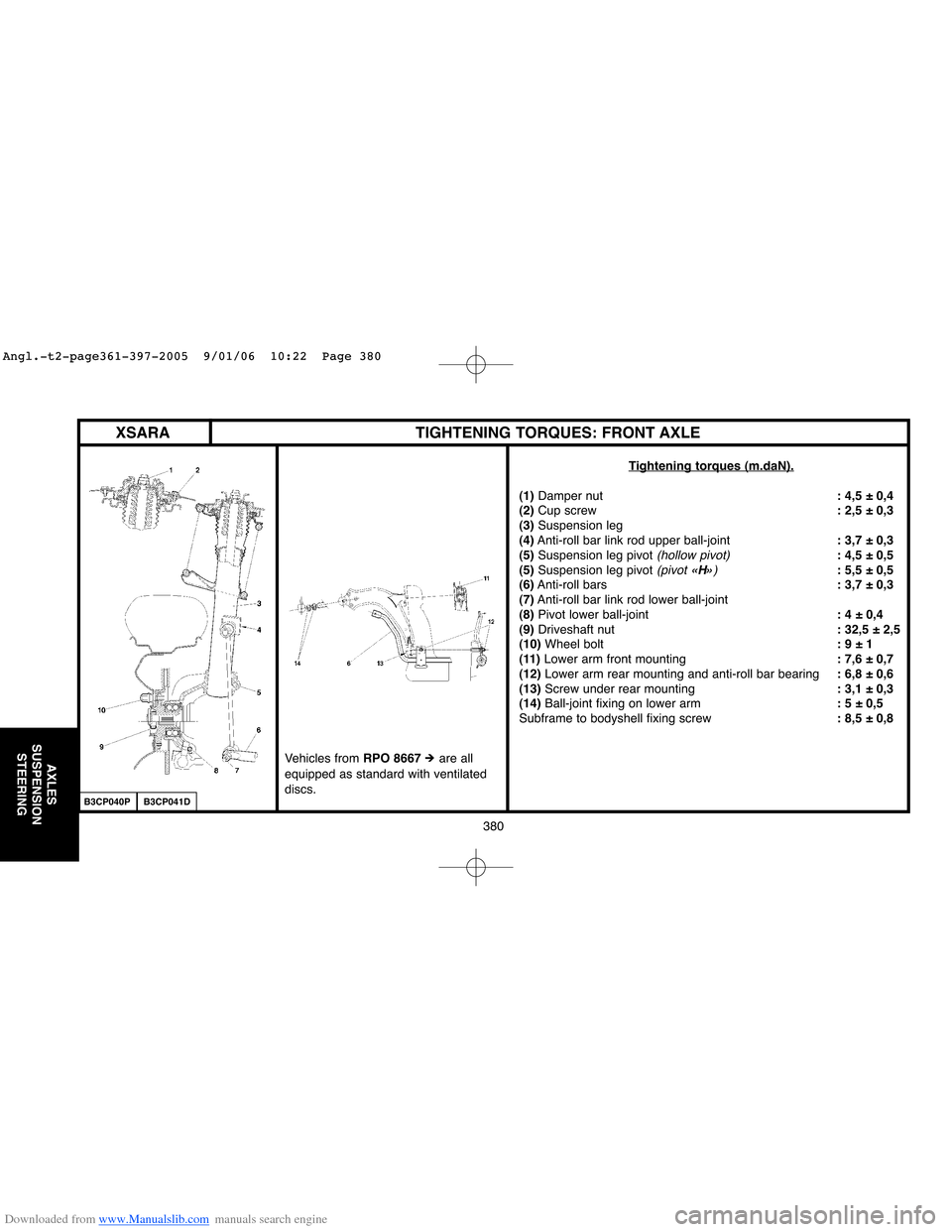
XSARA TIGHTENING TORQUES: FRONT AXLE
Tightening torques (m.daN).
(1)Damper nut: 4,5 ± 0,4
(2)Cup screw: 2,5 ± 0,3
(3)Suspension leg
(4)Anti-roll bar link rod upper ball-joint: 3,7 ± 0,3
(5)Suspension leg pivot
(hollow pivot): 4,5 ± 0,5
(5)Suspension leg pivot (pivot «H»): 5,5 ± 0,5
(6)Anti-roll bars: 3,7 ± 0,3
(7)Anti-roll bar link rod lower ball-joint
(8)Pivot lower ball-joint: 4 ± 0,4
(9) Driveshaft nut: 32,5 ± 2,5
(10)Wheel bolt: 9 ± 1
(11) Lower arm front mounting: 7,6 ± 0,7
(12)Lower arm rear mounting and anti-roll bar bearing: 6,8 ± 0,6
(13)Screw under rear mounting: 3,1 ± 0,3
(14) Ball-joint fixing on lower arm: 5 ± 0,5
Subframe to bodyshell fixing screw: 8,5 ± 0,8
B3CP040PB3CP041D
Vehicles from RPO 8667# are all
equipped as standard with ventilated
discs.
Angl.-t2-page361-397-2005 9/01/06 10:22 Page 380
Page 389 of 462
Downloaded from www.Manualslib.com manuals search engine 383
AXLES
SUSPENSION
STEERING
XSARA
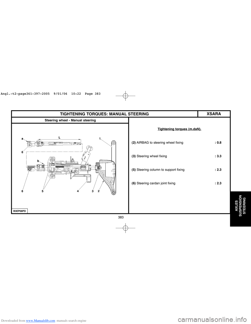
Steering wheel - Manual steering
TIGHTENING TORQUES: MANUAL STEERING
Tightening torques (m.daN).
(2)AIRBAG to steering wheel fixing: 0.8
(3)Steering wheel fixing: 3.3
(5)Steering column to support fixing: 2.3
(6)Steering cardan joint fixing: 2.3
B3EP08PD
Angl.-t2-page361-397-2005 9/01/06 10:22 Page 383
Page 391 of 462
Downloaded from www.Manualslib.com manuals search engine 385
AXLES
SUSPENSION
STEERING
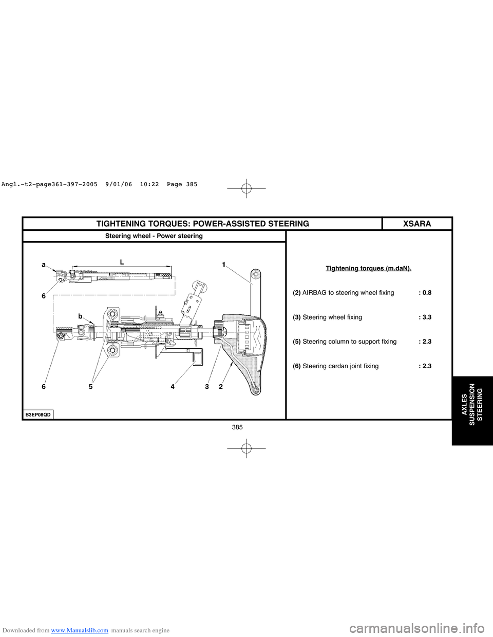
XSARA TIGHTENING TORQUES: POWER-ASSISTED STEERING
Steering wheel - Power steering
Tightening torques (m.daN).
(2)AIRBAG to steering wheel fixing: 0.8
(3) Steering wheel fixing: 3.3
(5)Steering column to support fixing: 2.3
(6)Steering cardan joint fixing: 2.3
B3EP08QD
Angl.-t2-page361-397-2005 9/01/06 10:22 Page 385
Page 394 of 462
Downloaded from www.Manualslib.com manuals search engine 388
AXLES
SUSPENSION
STEERING
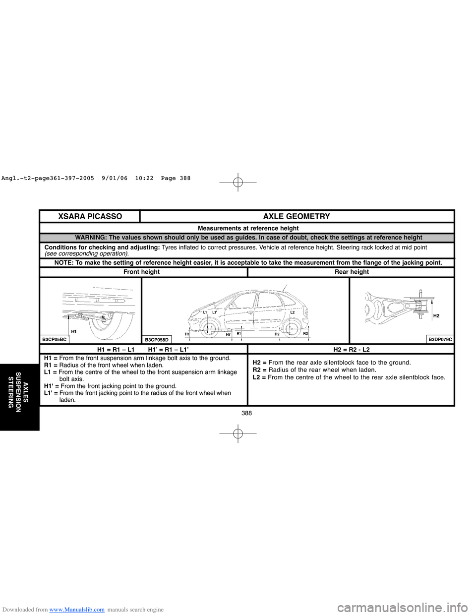
H1 = R1 – L1 H1’ = R1 – L1’
H1 = From the front suspension arm linkage bolt axis to the ground.
R1 =Radius of the front wheel when laden.
L1 =From the centre of the wheel to the front suspension arm linkage
bolt axis.
H1' =From the front jacking point to the ground.
L1' =From the front jacking point to the radius of the front wheel when
laden.H2 = R2 - L2
H2 = From the rear axle silentblock face to the ground.
R2 =Radius of the rear wheel when laden.
L2 =From the centre of the wheel to the rear axle silentblock face.
AXLE GEOMETRY
Measurements at reference height
NOTE: To make the setting of reference height easier, it is acceptable to take the measurement from the flange of the jacking point.
WARNING: The values shown should only be used as guides. In case of doubt, check the settings at reference height
Rear heightFront height
B3CP05BCB3CP058DB3DP079C
XSARA PICASSO
Conditions for checking and adjusting: Tyres inflated to correct pressures. Vehicle at reference height. Steering rack locked at mid point(see corresponding operation).
Angl.-t2-page361-397-2005 9/01/06 10:22 Page 388
Page 395 of 462
Downloaded from www.Manualslib.com manuals search engine 389
AXLES
SUSPENSION
STEERING
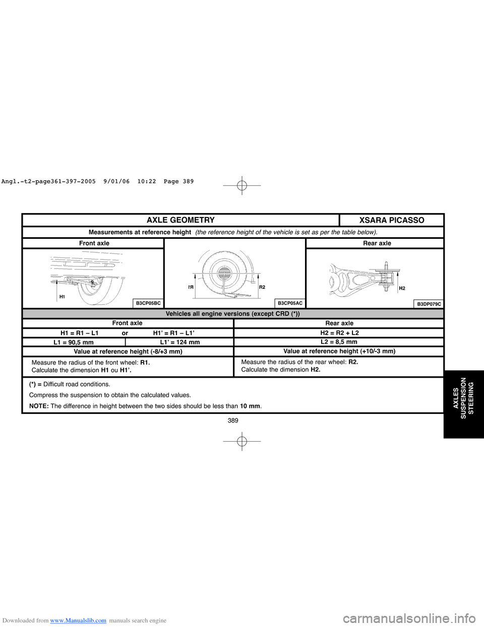
AXLE GEOMETRY
(*) = Difficult road conditions.
Compress the suspension to obtain the calculated values.
NOTE: The difference in height between the two sides should be less than10 mm. Measure the radius of the rear wheel: R2.
Calculate the dimensionH2. Measure the radius of the front wheel: R1.
Calculate the dimension H1 ouH1’.
Measurements at reference height (the reference height of the vehicle is set as per the table below).
B3CP05BCB3CP05AC
XSARA PICASSO
Front axleRear axle
Front axle
Rear axle Vehicles all engine versions (except CRD (*))
H1 = R1 – L1 or H1’ = R1 – L1’
L1 = 90,5 mmL1’ = 124 mmL2 = 8,5 mm H2 = R2 + L2
B3DP079C
Value at reference height (-8/+3 mm)Value at reference height (+10/-3 mm)
Angl.-t2-page361-397-2005 9/01/06 10:22 Page 389
Page 397 of 462
Downloaded from www.Manualslib.com manuals search engine 391
AXLES
SUSPENSION
STEERING
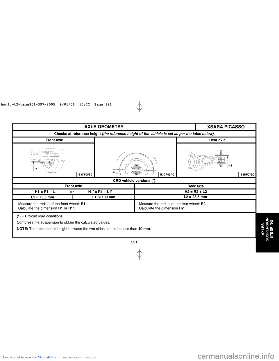
AXLE GEOMETRY
(*) = Difficult road conditions.
Compress the suspension to obtain the calculated values.
NOTE: The difference in height between the two sides should be less than10 mm. Measure the radius of the rear wheel: R2.
Calculate the dimensionH2. Measure the radius of the front wheel: R1.
Calculate the dimension H1 orH1’.
Checks at reference height (the reference height of the vehicle is set as per the table below).
B3CP05BCB3CP05AC
XSARA PICASSO
Front axleRear axle
Front axle
Rear axle CRD vehicle versions (*)
H1 = R1 – L1 or H1’ = R1 – L1’
L1 = 75,5 mmL1’ = 109 mmL2 = 23,5 mmH2 = R2 + L2
B3DP079C
Angl.-t2-page361-397-2005 9/01/06 10:22 Page 391
Page 399 of 462
Downloaded from www.Manualslib.com manuals search engine 393
AXLES
SUSPENSION
STEERING
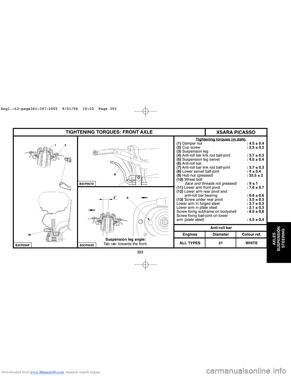
TIGHTENING TORQUES: FRONT AXLE
Tightening torques (m.daN).(1) Damper nut: 4.5 ± 0.4
(2)Cup screw: 2.5 ± 0.2
(3)Suspension leg
(4)Anti-roll bar link rod ball-joint: 3.7 ± 0.3
(5)Suspension leg swivel: 4.5 ± 0.4
(6)Anti-roll bar
(7)Anti-roll bar link rod ball-joint: 3.7 ± 0.3
(8)Lower swivel ball-joint: 4 ± 0.4
(9)Hub nut
(greased): 32.5 ± 2
(10)Wheel bolt
(face and threads not greased): 9 ± 1
(11) Lower arm front pivot: 7.6 ± 0.7
(12) Lower arm rear pivot and
anti-roll bar bearing: 6.8 ± 0.6
(13) Screw under rear pivot : 3.5 ± 0.3
Lower arm in forged steel : 3.7 ± 0,3
Lower arm in plate steel: 3.1 ± 0,3
Screw fixing subframe on bodyshell: 8.5 ± 0,8
Screw fixing ball-joint on lower
arm
(plate steel): 4.5 ± 0,4
Anti-roll bar
Engines
ALL TYPESDiameter
21Colour ref.
WHITE Suspension leg angle:
Ta b«a»towards the front.
B3CP056P
B3CP057D
B3CP043D
XSARA PICASSO
Angl.-t2-page361-397-2005 9/01/06 10:22 Page 393