Cooling Citroen C4 2005 2.G User Guide
[x] Cancel search | Manufacturer: CITROEN, Model Year: 2005, Model line: C4, Model: Citroen C4 2005 2.GPages: 462, PDF Size: 10.48 MB
Page 95 of 462
Downloaded from www.Manualslib.com manuals search engine 89
ENGINE
89
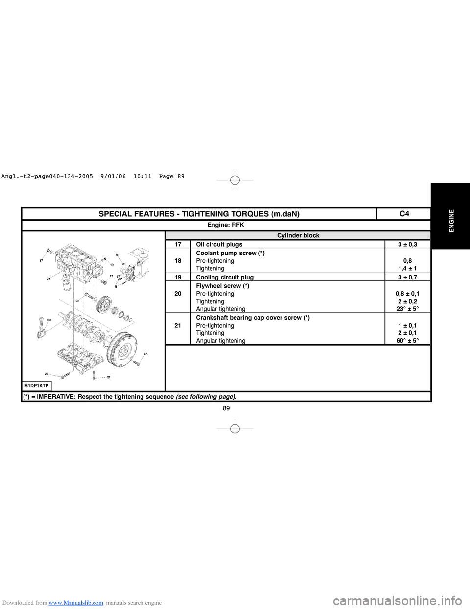
SPECIAL FEATURES - TIGHTENING TORQUES (m.daN)
Cylinder block
17 Oil circuit plugs 3 ± 0,3
Coolant pump screw (*)
18Pre-tightening0,8
Tightening1,4 ± 1
19 Cooling circuit plug 3 ± 0,7
Flywheel screw (*)
20Pre-tightening0,8 ± 0,1
Tightening2 ± 0,2
Angular tightening23°±5°
Crankshaft bearing cap cover screw (*)
21Pre-tightening1 ± 0,1
Tightening2 ± 0,1
Angular tightening60°±5°
Engine: RFK
B1DP1KTP
(*) = IMPERATIVE: Respect the tightening sequence (see following page).
C4
Angl.-t2-page040-134-2005 9/01/06 10:11 Page 89
Page 104 of 462
Downloaded from www.Manualslib.com manuals search engine 98
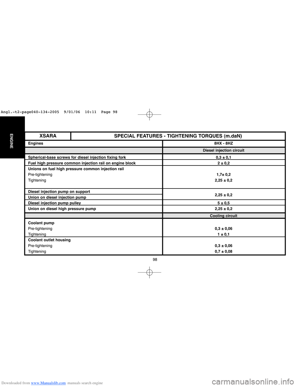
ENGINESPECIAL FEATURES - TIGHTENING TORQUES (m.daN)
Engines8HX - 8HZ
Diesel injection circuit
Spherical-base screws for diesel injection fixing fork 0,3 ± 0,1
Fuel high pressure common injection rail on engine block 2 ± 0,2
Unions on fuel high pressure common injection rail
Pre-tightening1,7± 0,2
Tightening2,25 ± 0,2
Diesel injection pump on support
Union on diesel injection pump2,25 ± 0,2
Diesel injection pump pulley5 ± 0,5
Union on diesel high pressure pump 2,25 ± 0,2
Cooling circuit
Coolant pump
Pre-tightening0,3 ± 0,06
Tightening1 ± 0,1
Coolant outlet housing
Pre-tightening0,3 ± 0,06
Tightening0,7 ± 0,08
XSARA
Angl.-t2-page040-134-2005 9/01/06 10:11 Page 98
Page 135 of 462
Downloaded from www.Manualslib.com manuals search engine 129
ENGINE
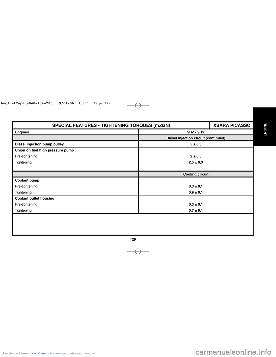
XSARA PICASSOSPECIAL FEATURES - TIGHTENING TORQUES (m.daN)
Engines9HZ - 9HY
Diesel injection circuit (continued)
Diesel injection pump pulley5 ± 0,5
Union on fuel high pressure pump
Pre-tightening2 ± 0,5
Tightening2,5 ± 0,3
Cooling circuit
Coolant pump
Pre-tightening0,3 ± 0,1
Tightening0,9 ± 0,1
Coolant outlet housing
Pre-tightening0,3 ± 0,1
Tightening0,7 ± 0,1
Angl.-t2-page040-134-2005 9/01/06 10:11 Page 129
Page 139 of 462
Downloaded from www.Manualslib.com manuals search engine 133
ENGINE
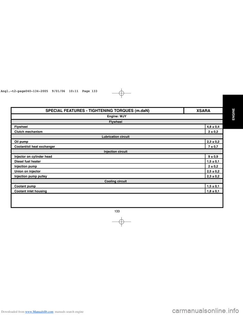
SPECIAL FEATURES - TIGHTENING TORQUES (m.daN)
Flywheel
Flywheel4,8 ± 0,4
Clutch mechanism2 ± 0,2
Lubrication circuit
Oil pump2,3 ± 0,2
Coolant/oil heat exchanger7 ± 0,7
Injection circuit
Injector on cylinder head9 ± 0,9
Diesel fuel heater1,5 ± 0,1
Injection pump2 ± 0,2
Union on injector2,5 ± 0,2
Injection pump pulley2,3 ± 0,2
Cooling circuit
Coolant pump1,5 ± 0,1
Coolant inlet housing1,8 ± 0,1 Engine: WJY
XSARA
Angl.-t2-page040-134-2005 9/01/06 10:11 Page 133
Page 142 of 462
Downloaded from www.Manualslib.com manuals search engine 136
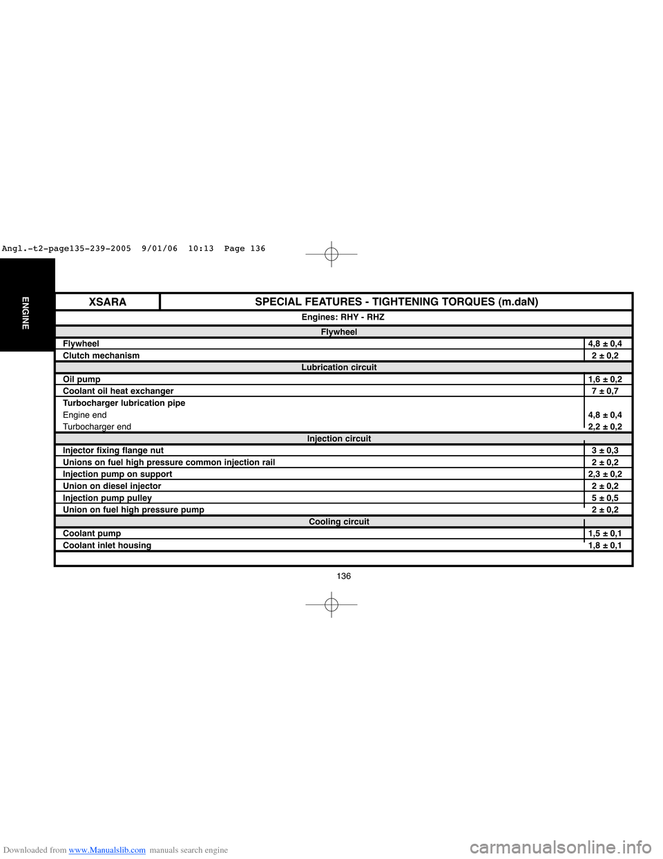
ENGINESPECIAL FEATURES - TIGHTENING TORQUES (m.daN)
Flywheel
Flywheel4,8 ± 0,4
Clutch mechanism2 ± 0,2
Lubrication circuit
Oil pump1,6 ± 0,2
Coolant oil heat exchanger7 ± 0,7
Turbocharger lubrication pipe
Engine end4,8 ± 0,4
Turbocharger end2,2 ± 0,2
Injection circuit
Injector fixing flange nut3 ± 0,3
Unions on fuel high pressure common injection rail2 ± 0,2
Injection pump on support2,3 ± 0,2
Union on diesel injector2 ± 0,2
Injection pump pulley5 ± 0,5
Union on fuel high pressure pump2 ± 0,2
Cooling circuit
Coolant pump1,5 ± 0,1
Coolant inlet housing1,8 ± 0,1 Engines: RHY - RHZ
XSARA
Angl.-t2-page135-239-2005 9/01/06 10:13 Page 136
Page 270 of 462
![Citroen C4 2005 2.G User Guide Downloaded from www.Manualslib.com manuals search engine 264
ENGINECHECKING AND SETTING THE VALVE TIMING
Tools.
[1]Belt tension measuring equipment : 4122-T
[2]Tension lever: (-).0188.J2
[3]Engine fly Citroen C4 2005 2.G User Guide Downloaded from www.Manualslib.com manuals search engine 264
ENGINECHECKING AND SETTING THE VALVE TIMING
Tools.
[1]Belt tension measuring equipment : 4122-T
[2]Tension lever: (-).0188.J2
[3]Engine fly](/img/9/4138/w960_4138-269.png)
Downloaded from www.Manualslib.com manuals search engine 264
ENGINECHECKING AND SETTING THE VALVE TIMING
Tools.
[1]Belt tension measuring equipment : 4122-T
[2]Tension lever: (-).0188.J2
[3]Engine flywheel peg: (-).0188.Y
[4] Belt clamp: (-).0188.AD
[5]Camshaft pulley peg: (-).0188.M
[6] Engine flywheel lock: (-).0188.F
[7] Set of blocking plugs: (-).0188.T
[8] Pulley extractor: (-).0188.P
[9] 2 mm Øpeg: (-).0188.Q2Removing.
IMPERATIVE: Respect the safety and cleanliness requirements
that are specific to high pressure diesel injection (HDi) engines.
Undo the front RH wheel bolts.
Raise and support the vehicle on the front RH side.
Disconnect the battery negative terminal.
Remove:
- The under-engine sound-deadening.
- The front RH wheel.
- The front RH splash-shield.
- The engine cover.
Unclip and move aside the cooling hose.
Remove the accessories drive belt
(see corresponding operation).
XSARA - XSARA PICASSO
Engines: RHY - RHZ
Angl.-t2-page240-282-2005 9/01/06 10:16 Page 264
Page 276 of 462
![Citroen C4 2005 2.G User Guide Downloaded from www.Manualslib.com manuals search engine 270
ENGINECHECKING AND SETTING THE VALVE TIMING
Engines: RHY - RHZ
Remove:
- Tools [3]and [5], Screw (7)and the spacer.
Refit:
- The lower, i Citroen C4 2005 2.G User Guide Downloaded from www.Manualslib.com manuals search engine 270
ENGINECHECKING AND SETTING THE VALVE TIMING
Engines: RHY - RHZ
Remove:
- Tools [3]and [5], Screw (7)and the spacer.
Refit:
- The lower, i](/img/9/4138/w960_4138-275.png)
Downloaded from www.Manualslib.com manuals search engine 270
ENGINECHECKING AND SETTING THE VALVE TIMING
Engines: RHY - RHZ
Remove:
- Tools [3]and [5], Screw (7)and the spacer.
Refit:
- The lower, intermediate and upper covers (5).
- Screw (7), tighten to 1,5 ± 0,1 m.daN.
- Screws (3), (4)and (6).
- The bracket (13).
Screws (11), tighten to 6,1 ± 0,5 m.daN.
The nut (12), tighten to 4,5 ± 0,5 m.daN.
Fit the bearing shell (10).
Take away the workshop hoist.
Clip the fuel delivery and return pipes.
Remove the tool [7].
Couple:
- The fuel delivery pipe (12).
- The fuel return pipe (1).
- Coat the screw (8)with loctite FRENETANCH.
Refit the tool [6]and the screw (8)with the washer (22), tighten to 7 ± 0,2 m.daN
and angular tighten to A= 60°±5°.
Refit the torque reaction rod on the lower engine support.
Remove the tool [6].
Reposition and reclip the cooling hose.
Complete the refitting of components in reverse order to removal.
B1EP1A7CB1BP2R4CB1EP1ADC
XSARA - XSARA PICASSO
Angl.-t2-page240-282-2005 9/01/06 10:16 Page 270
Page 441 of 462
![Citroen C4 2005 2.G User Guide Downloaded from www.Manualslib.com manuals search engine 435
AIR
CONDITIONING
SPECIAL FEATURES: AIR CONDITIONING SYSTEM (R 134.a)
Changing the filtering/drying cartridge
Tools.
[1]Charge station:
( Citroen C4 2005 2.G User Guide Downloaded from www.Manualslib.com manuals search engine 435
AIR
CONDITIONING
SPECIAL FEATURES: AIR CONDITIONING SYSTEM (R 134.a)
Changing the filtering/drying cartridge
Tools.
[1]Charge station:
(](/img/9/4138/w960_4138-440.png)
Downloaded from www.Manualslib.com manuals search engine 435
AIR
CONDITIONING
SPECIAL FEATURES: AIR CONDITIONING SYSTEM (R 134.a)
Changing the filtering/drying cartridge
Tools.
[1]Charge station:
(according to workshop equipment)[2]TORX adaptor: TORX 70 FACOM
Removing.
Depressurise the aircon circuit, using tool [1].
Uncouple the hose (2).
Remove:
- The air filter assembly (3).
- The nuts (1).
Protect the radiator harness with strong cardboard cut to the dimensions of the radiator.
Move aside the cooling fan.
Remove:
- The screws (4).
- The brackets (5).
B1BP23FCB1BP23GC
XSARA PICASSO
Angl.-t2-page428-456-2005 9/01/06 10:25 Page 435
Page 446 of 462
Downloaded from www.Manualslib.com manuals search engine 440
AIR
CONDITIONING
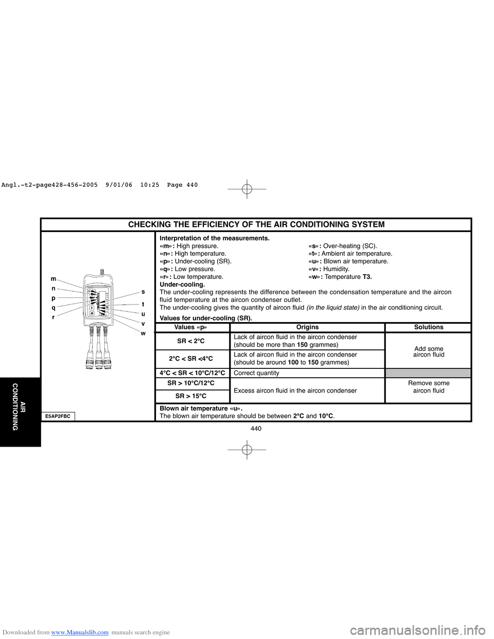
CHECKING THE EFFICIENCY OF THE AIR CONDITIONING SYSTEM
Interpretation of the measurements.
«m»:High pressure.«s»:Over-heating (SC).
«n»:High temperature.«t»:Ambient air temperature.
«p»:Under-cooling (SR).«u»:Blown air temperature.
«q»:Low pressure.«v»: Humidity.
«r»:Low temperature.«w»: Temperature T3.
Under-cooling.
The under-cooling represents the difference between the condensation temperature and the aircon
fluid temperature at the aircon condenser outlet.
The under-cooling gives the quantity of aircon fluid
(in the liquid state)in the air conditioning circuit.
Values for under-cooling (SR).
Values «p» Origins Solutions
SR < 2°CLack of aircon fluid in the aircon condenser
(should be more than 150grammes)
Add some
2°C < SR <4°CLack of aircon fluid in the aircon condenser aircon fluid
(should be around 100to 150grammes)
4°C < SR < 10°C/12°CCorrect quantity
SR > 10°C/12°CRemove some
Excess aircon fluid in the aircon condenser aircon fluid
SR > 15°C
Blown air temperature «u».
The blown air temperature should be between 2°Cand 10°C.
E5AP2FBC
Angl.-t2-page428-456-2005 9/01/06 10:25 Page 440
Page 447 of 462
Downloaded from www.Manualslib.com manuals search engine 441
AIR
CONDITIONING
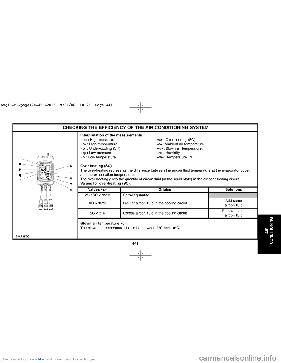
CHECKING THE EFFICIENCY OF THE AIR CONDITIONING SYSTEM
Interpretation of the measurements.
«m»:High pressure.«s»: Over-heating (SC).
«n»:High temperature.«t»:Ambient air temperature.
«p»:Under-cooling (SR).«u»:Blown air temperature.
«q»:Low pressure.«v»:Humidity.
«r»: Low temperature.«w»: Temperature T3.
Over-heating (SC).
The over-heating represents the difference between the aircon fluid temperature at the evaporator outlet
and the evaporation temperature.
The over-heating gives the quantity of aircon fluid (in the liquid state) in the air conditioning circuit
Values for over-heating (SC).
Values «s» Origins Solutions
2° < SC < 15°CCorrect quantity
SC > 15°CLack of aircon fluid in the cooling circuitAdd some
aircon fluid
SC < 2°CExcess aircon fluid in the cooling circuitRemove some
aircon fluid
Blown air temperature «u».
The blown air temperature should be between 2°Cand 10°C.
E5AP2FBC
Angl.-t2-page428-456-2005 9/01/06 10:25 Page 441