pipe Citroen C4 2005 2.G Owner's Guide
[x] Cancel search | Manufacturer: CITROEN, Model Year: 2005, Model line: C4, Model: Citroen C4 2005 2.GPages: 462, PDF Size: 10.48 MB
Page 393 of 462
Downloaded from www.Manualslib.com manuals search engine 387
AXLES
SUSPENSION
STEERING
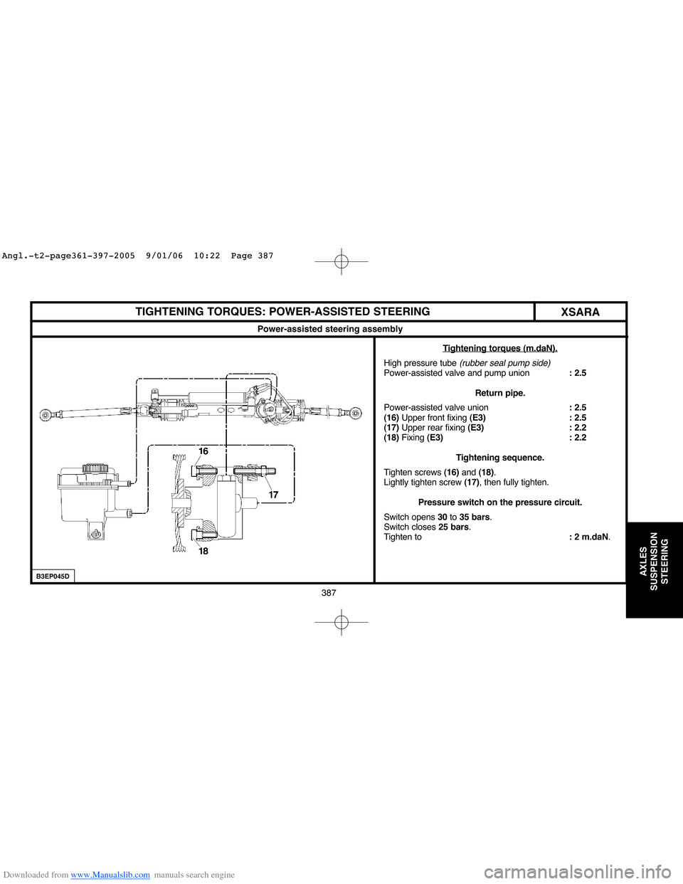
TIGHTENING TORQUES: POWER-ASSISTED STEERING
XSARA
Power-assisted steering assembly
T
ightening torques (m.daN).
High pressure tube (rubber seal pump side)Power-assisted valve and pump union: 2.5
Return pipe.
Power-assisted valve union: 2.5
(16)Upper front fixing (E3) : 2.5
(17)Upper rear fixing (E3) : 2.2
(18)Fixing (E3) : 2.2
Tightening sequence.
Tighten screws (16) and (18).
Lightly tighten screw (17), then fully tighten.
Pressure switch on the pressure circuit.
Switch opens 30to 35 bars.
Switch closes 25 bars.
Tighten to: 2 m.daN.
B3EP045D
Angl.-t2-page361-397-2005 9/01/06 10:22 Page 387
Page 402 of 462
Downloaded from www.Manualslib.com manuals search engine 396
AXLES
SUSPENSION
STEERING
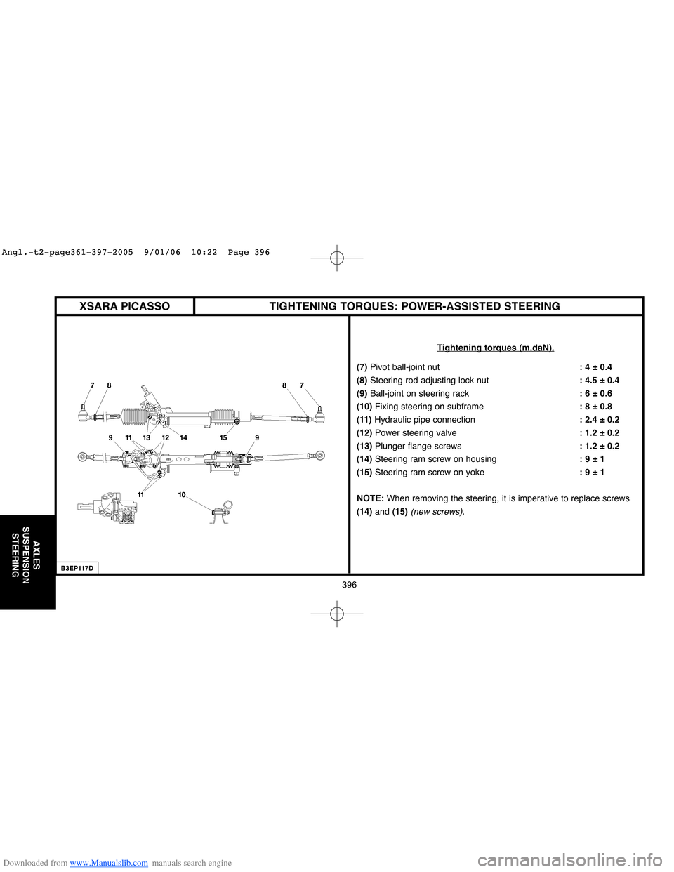
TIGHTENING TORQUES: POWER-ASSISTED STEERING
Tightening torques (m.daN).
(7) Pivot ball-joint nut: 4 ± 0.4
(8) Steering rod adjusting lock nut: 4.5 ± 0.4
(9)Ball-joint on steering rack: 6 ± 0.6
(10) Fixing steering on subframe: 8 ± 0.8
(11)Hydraulic pipe connection: 2.4 ± 0.2
(12)Power steering valve: 1.2 ± 0.2
(13)Plunger flange screws: 1.2 ± 0.2
(14)Steering ram screw on housing: 9 ± 1
(15) Steering ram screw on yoke: 9 ± 1
NOTE:When removing the steering, it is imperative to replace screws
(14)and (15)
(new screws).
B3EP117D
XSARA PICASSO
Angl.-t2-page361-397-2005 9/01/06 10:22 Page 396
Page 404 of 462
Downloaded from www.Manualslib.com manuals search engine 398
BRAKES
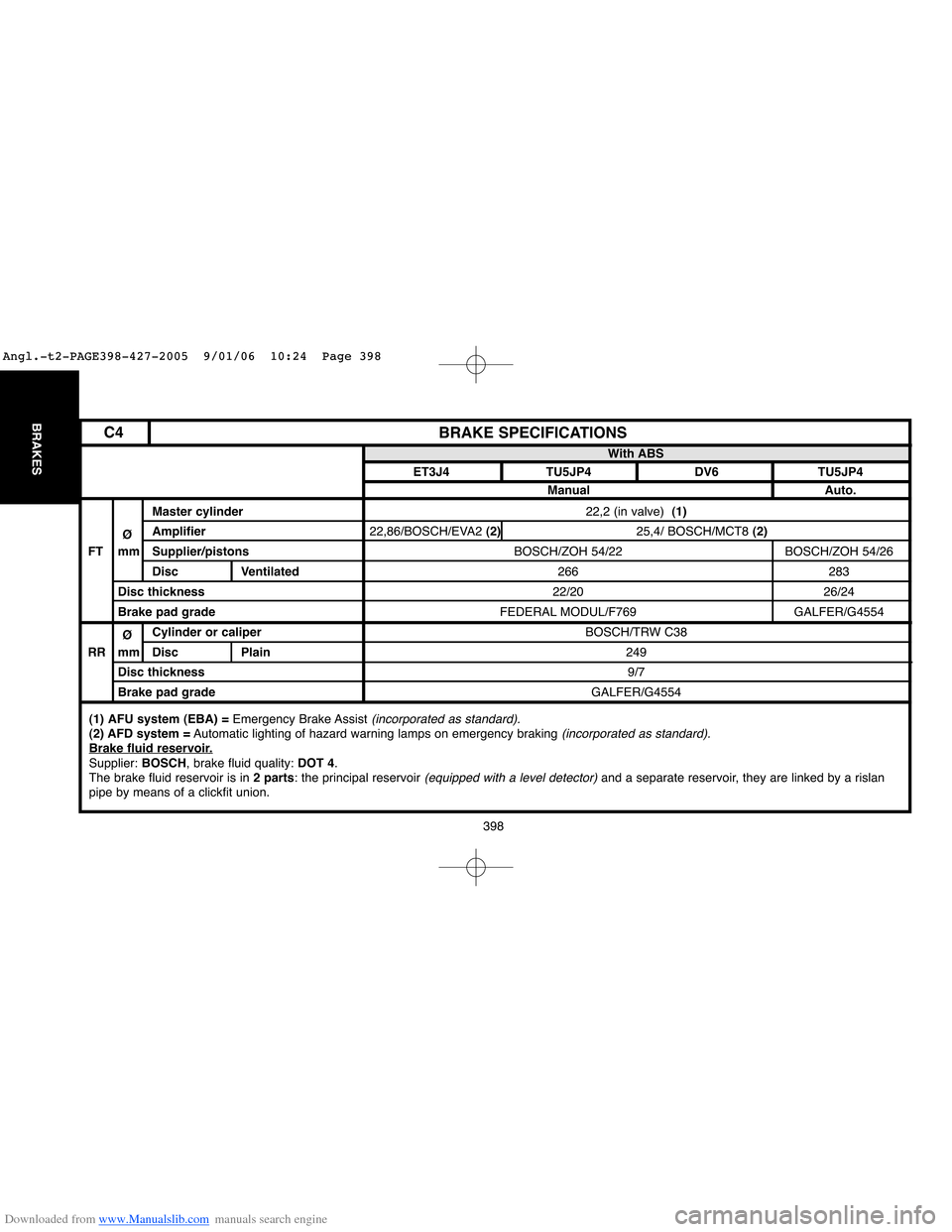
22,2 (in valve) (1)
22,86/BOSCH/EVA2 (2)25,4/ BOSCH/MCT8 (2)
BOSCH/ZOH 54/22 BOSCH/ZOH 54/26
266 283
22/20 26/24
FEDERAL MODUL/F769 GALFER/G4554
BOSCH/TRW C38
249
9/7
GALFER/G4554
BRAKE SPECIFICATIONS
Master cylinder
ØAmplifier
FT mm Supplier/pistons
Disc Ventilated
Disc thickness
Brake pad grade
ØCylinder or caliper
RR mm Disc Plain
Disc thickness
Brake pad gradeWith ABS
ET3J4 TU5JP4 DV6 TU5JP4
Manual Auto.
(1) AFU system (EBA) =Emergency Brake Assist (incorporated as standard).(2) AFD system =Automatic lighting of hazard warning lamps on emergency braking (incorporated as standard).Brake fluid reservoir.Supplier: BOSCH, brake fluid quality: DOT 4.
The brake fluid reservoir is in 2 parts: the principal reservoir (equipped with a level detector)and a separate reservoir, they are linked by a rislan
pipe by means of a clickfit union.
C4
Angl.-t2-PAGE398-427-2005 9/01/06 10:24 Page 398
Page 405 of 462
Downloaded from www.Manualslib.com manuals search engine 399
BRAKES
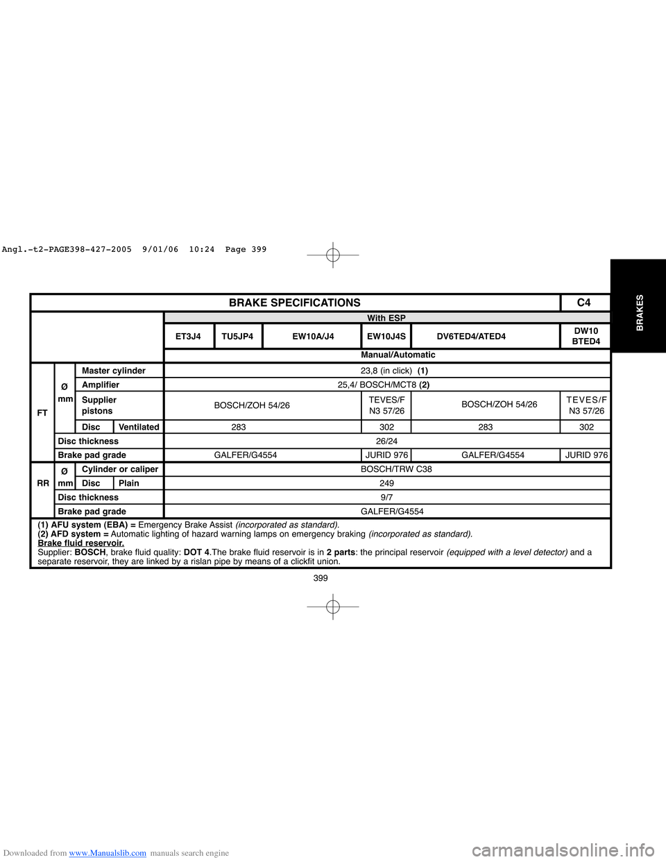
23,8 (in click) (1)
25,4/ BOSCH/MCT8 (2)
BOSCH/ZOH 54/26TEVES/F
BOSCH/ZOH 54/26TEVES/F
N3 57/26 N3 57/26
283 302 283 302
26/24
GALFER/G4554 JURID 976 GALFER/G4554 JURID 976
BOSCH/TRW C38
249
9/7
GALFER/G4554
BRAKE SPECIFICATIONS
Master cylinder
ØAmplifier
mm
Supplier
FTpistons
Disc Ventilated
Disc thickness
Brake pad grade
ØCylinder or caliper
RR mm Disc Plain
Disc thickness
Brake pad gradeWith ESP
ET3J4 TU5JP4 EW10A/J4 EW10J4S DV6TED4/ATED4DW10
BTED4
Manual/Automatic
(1) AFU system (EBA) =Emergency Brake Assist (incorporated as standard).(2) AFD system =Automatic lighting of hazard warning lamps on emergency braking (incorporated as standard).Brake fluid reservoir.Supplier: BOSCH, brake fluid quality: DOT 4.The brake fluid reservoir is in 2 parts: the principal reservoir (equipped with a level detector)and a
separate reservoir, they are linked by a rislan pipe by means of a clickfit union.
C4
Angl.-t2-PAGE398-427-2005 9/01/06 10:24 Page 399
Page 413 of 462
Downloaded from www.Manualslib.com manuals search engine 407
BRAKES
B3FP7ESD
BLEEDING AND FILLING THE BRAKING SYSTEM
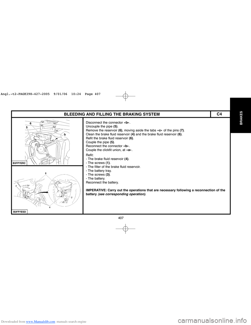
Disconnect the connector «b».
Uncouple the pipe (5).
Remove the reservoir (6), moving aside the tabs «c»of the pins (7).
Clean the brake fluid reservoir (4) and the brake fluid reservoir (6).
Refit the brake fluid reservoir (6).
Couple the pipe (5).
Reconnect the connector «b».
Couple the clickfit union, at «a».
Refit:
- The brake fluid reservoir (4).
- The screws (1).
- The filter of the brake fluid reservoir.
- The battery tray.
- The screws (3).
- The battery.
Reconnect the battery.
IMPERATIVE: Carry out the operations that are necessary following a reconnection of the
battery
(see corresponding operation).
B3FP7ERC
C4
Angl.-t2-PAGE398-427-2005 9/01/06 10:24 Page 407
Page 433 of 462
Downloaded from www.Manualslib.com manuals search engine 427
BRAKES
BLEEDING THE BRAKING SYSTEMXSARA PICASSO
Tools Bleeding equipment of type «LURO» or similar.
IMPERATIVE: For bleeding the secondary circuit, use ELIT, LEXIA or PROXIA diagnostic tools.
Draining.
Drain the brake fluid reservoir as empty as possible using a syringe.
Disconnect the brake fluid warning lamp connector.
Retrieve the brake fluid reservoir from its supply pipes by pulling upwards.
Finish emptying the reservoir of brake fluid.
Clean the brake fluid reservoir.
Refit the brake fluid reservoir.
Reconnect the brake fluid warning lamp connector.
Filling.
Refill the reservoir with brake fluid.
WARNING: Use only the recommended hydraulic fluids.
Bleeding.
NOTE:Two technicians are required.
IMPERATIVE: During bleed operations, ensure that the level of brake fluid is maintained
in the reservoir and top it up, use only new brake fluid.
Bleed each wheel cylinder, proceeding in the following order:
- Rear right hand wheel.
- Front left hand wheel.
- Rear left hand wheel.
- Front right hand wheel.
Angl.-t2-PAGE398-427-2005 9/01/06 10:24 Page 427
Page 436 of 462
Downloaded from www.Manualslib.com manuals search engine 430
AIR
CONDITIONING
Checking the compressor oil level (continued)
2/ Slow leak.
Slow leaks do not lead to oil loss, therefore the same procedure should be followed as if there was no leak at all.
3/ Fast leak.
This type of leak causes both oil loss as well as allowing air to enter the system.
It is therefore necessary to:
- Replace the dehydrator.
- Drain as much oil as possible
(when replacing the faulty component).
Either before or during filling of the system with R 134.afluid, introduce 80 ccof NEWoil into the circuit.
When changing one of the following components, add the quantity stated:
- A drying bottle : 15 ccof compressor oil.
- A condenser or an evaporator : 20 ccof compressor oil.
- High pressure or low pressure pipework : 5 ccof compressor oil.
- A drying cartridge : 15 ccof compressor oil.
SPECIAL FEATURES: AIR CONDITIONING SYSTEM (R 134.a)
Angl.-t2-page428-456-2005 9/01/06 10:25 Page 430
Page 458 of 462
Downloaded from www.Manualslib.com manuals search engine 452
AIR
CONDITIONING
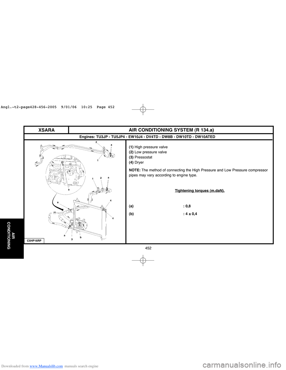
(1)High pressure valve
(2)Low pressure valve
(3)Pressostat
(4)Dryer
NOTE:The method of connecting the High Pressure and Low Pressure compressor
pipes may vary according to engine type.
T
ightening torques (m.daN).
(a) : 0,8
(b) : 4 ± 0,4
XSARAAIR CONDITIONING SYSTEM (R 134.a)
C5HP16RP
Engines: TU3JP - TU5JP4 - EW10J4 - DV4TD - DW8B - DW10TD - DW10ATED
Angl.-t2-page428-456-2005 9/01/06 10:25 Page 452