pipe Citroen C4 2005 2.G Owner's Manual
[x] Cancel search | Manufacturer: CITROEN, Model Year: 2005, Model line: C4, Model: Citroen C4 2005 2.GPages: 462, PDF Size: 10.48 MB
Page 294 of 462
![Citroen C4 2005 2.G Owners Manual Downloaded from www.Manualslib.com manuals search engine 288
INJECTION
CHECKS: LOW PRESSURE FUEL SUPPLY CIRCUIT
Tools.
[1] Ø 10 mm low pressure connector: 4215-T
[2] Ø 8 mmlow pressure connector: 42 Citroen C4 2005 2.G Owners Manual Downloaded from www.Manualslib.com manuals search engine 288
INJECTION
CHECKS: LOW PRESSURE FUEL SUPPLY CIRCUIT
Tools.
[1] Ø 10 mm low pressure connector: 4215-T
[2] Ø 8 mmlow pressure connector: 42](/img/9/4138/w960_4138-293.png)
Downloaded from www.Manualslib.com manuals search engine 288
INJECTION
CHECKS: LOW PRESSURE FUEL SUPPLY CIRCUIT
Tools.
[1] Ø 10 mm low pressure connector: 4215-T
[2] Ø 8 mmlow pressure connector: 4218-T
[3]Pressure gauge for testing boost pressure: 4073-T Kit 4073-T
Connect the tool [1]between the booster pump and the fuel filter
(white mark at "a" on the fuel
supply pipe).
Connect the tool [2]downstream of the diesel injectors, between the high pressure fuel pump and
the fuel filter
(green mark at "b" on the fuel return pipe).
WARNING: Any check of pressure downstream of the fuel filter is PROHIBITED.
Checks on pressure: static.
- Switch on ignition.
For 3 seconds
(normal functioning):
- Fuel supply pressure shown by the pressure gauge [3] = 1.8 ± 0.4 bar.
- Fuel return pressure shown by the pressure gauge [3] = 0.5 ± 0.4 bar.
B1BP1TWD
Engines: RHY - RHZ
XSARA PICASSO
Angl.-t2-page283-305-2005 9/01/06 10:18 Page 288
Page 295 of 462
Downloaded from www.Manualslib.com manuals search engine 289
INJECTION
CHECKS: LOW PRESSURE FUEL SUPPLY CIRCUIT
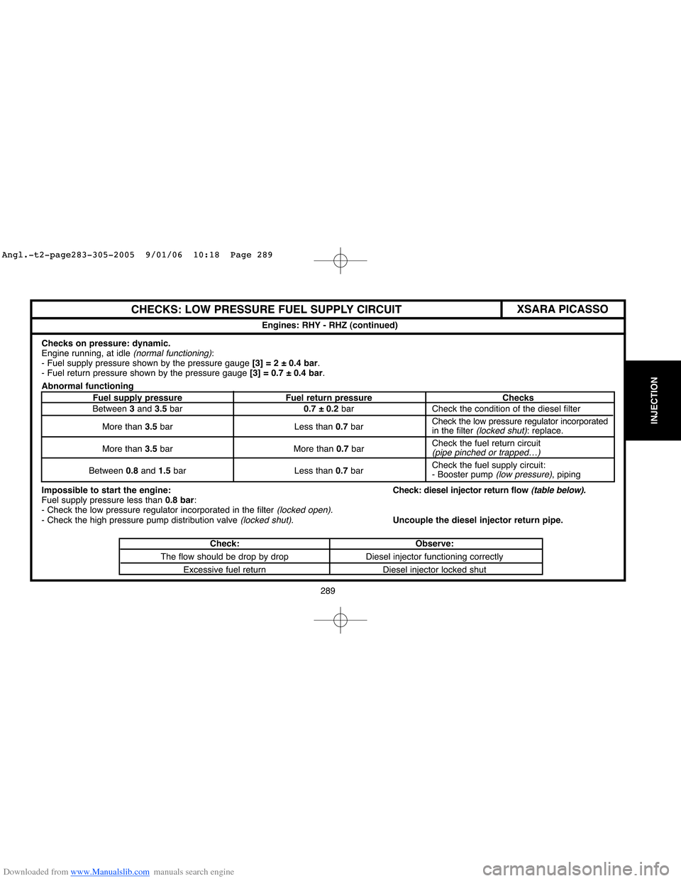
Checks on pressure: dynamic.
Engine running, at idle (normal functioning):
- Fuel supply pressure shown by the pressure gauge [3] = 2 ± 0.4 bar.
- Fuel return pressure shown by the pressure gauge [3] = 0.7 ± 0.4 bar.
Abnormal functioning
Fuel supply pressure Fuel return pressure Checks
Between 3and 3.5bar0.7 ± 0.2 bar Check the condition of the diesel filter
More than 3.5bar Less than 0.7barCheck the low pressure regulator incorporated
in the filter
(locked shut): replace.
More than 3.5bar More than 0.7barCheck the fuel return circuit
(pipe pinched or trapped…)
Between 0.8and 1.5bar Less than 0.7barCheck the fuel supply circuit:
- Booster pump (low pressure), piping
Impossible to start the engine:Check: diesel injector return flow
(table below).Fuel supply pressure less than 0.8 bar:
- Check the low pressure regulator incorporated in the filter (locked open).- Check the high pressure pump distribution valve (locked shut).Uncouple the diesel injector return pipe.
Check: Observe:
The flow should be drop by drop Diesel injector functioning correctly
Excessive fuel return Diesel injector locked shutEngines: RHY - RHZ (continued)
XSARA PICASSO
Angl.-t2-page283-305-2005 9/01/06 10:18 Page 289
Page 300 of 462
![Citroen C4 2005 2.G Owners Manual Downloaded from www.Manualslib.com manuals search engine 294
INJECTION
CHECKS: TURBO PRESSURE
Tools.
[1]Pressure gauge for checking boost pressure: 4073-T.A Kit 4073-T
[2]Sleeve for checking boost pre Citroen C4 2005 2.G Owners Manual Downloaded from www.Manualslib.com manuals search engine 294
INJECTION
CHECKS: TURBO PRESSURE
Tools.
[1]Pressure gauge for checking boost pressure: 4073-T.A Kit 4073-T
[2]Sleeve for checking boost pre](/img/9/4138/w960_4138-299.png)
Downloaded from www.Manualslib.com manuals search engine 294
INJECTION
CHECKS: TURBO PRESSURE
Tools.
[1]Pressure gauge for checking boost pressure: 4073-T.A Kit 4073-T
[2]Sleeve for checking boost pressure: 4185-T
Checks.
IMPERATIVE: respect the following checking requirements: Engine at running temperature.
Vehicle running at full load.
Preparation.
Remove the collar (3)and the sleeve.
Insert the tool [2]between the pipe (1)and the duct (2).
Position tool [1]in the vehicle.
Connect the pressure gauge [1]to the tool [2] with its tube «a»long enough for the gauge to be
positioned inside the vehicle.
Procedure.
Start the engine.
Engage first gearand start the engine.
Engage the gears up to third gear.
Decelerate to 2000 rpm.
Gradually accelerate.
Check the pressure: 0.95 ± 0.05 bar.
Remove the tools, refit the collars (3) and the sleeve.
B1BP1ZXD
Engine: RHY
XSARA PICASSO
Angl.-t2-page283-305-2005 9/01/06 10:18 Page 294
Page 301 of 462
![Citroen C4 2005 2.G Owners Manual Downloaded from www.Manualslib.com manuals search engine 295
INJECTION
CHECKS: TURBO PRESSURE
Tools.
[1]Pressure gauge for checking boost pressure: 4073-T.A Kit 4073-T
[2] Sleeve for checking boost pr Citroen C4 2005 2.G Owners Manual Downloaded from www.Manualslib.com manuals search engine 295
INJECTION
CHECKS: TURBO PRESSURE
Tools.
[1]Pressure gauge for checking boost pressure: 4073-T.A Kit 4073-T
[2] Sleeve for checking boost pr](/img/9/4138/w960_4138-300.png)
Downloaded from www.Manualslib.com manuals search engine 295
INJECTION
CHECKS: TURBO PRESSURE
Tools.
[1]Pressure gauge for checking boost pressure: 4073-T.A Kit 4073-T
[2] Sleeve for checking boost pressure: 4185-T
[3]Adaptor sleeve: 4229-T
Checks.
IMPERATIVE: respect the following checking requirements: Engine at running temperature.
Vehicle in running order at full load.
Preparation.
Remove the collar fixing (3).
Insert the tool [2]connected with tool [3], between the pipe (1)and the duct (2).
Position tool [1]in the vehicle.
Connect the sleeve [2]to the tool [1]with its tube «a».
Procedure.
Start the engine.
Engage first gear and start the engine.
Engage the gears up to third gear.
Decelerate to 1000 rpm.
Accelerate hard, and check the pressure: 0.6 ± 0.05 bar
(1500 rpm).
Accelerate freely in kick-down (changing from fourthto third gear).
Check the pressure: 0.95 ± 0.05 bar (between 2500and 3500rpm).
Remove the tools, reposition the pipe (1)and refit the collar (3).
B1HP12JD
Engine: RHZ
XSARA PICASSO
Angl.-t2-page283-305-2005 9/01/06 10:18 Page 295
Page 333 of 462
Downloaded from www.Manualslib.com manuals search engine 327
CLUTCH
GEARBOX
TRANSMISSION
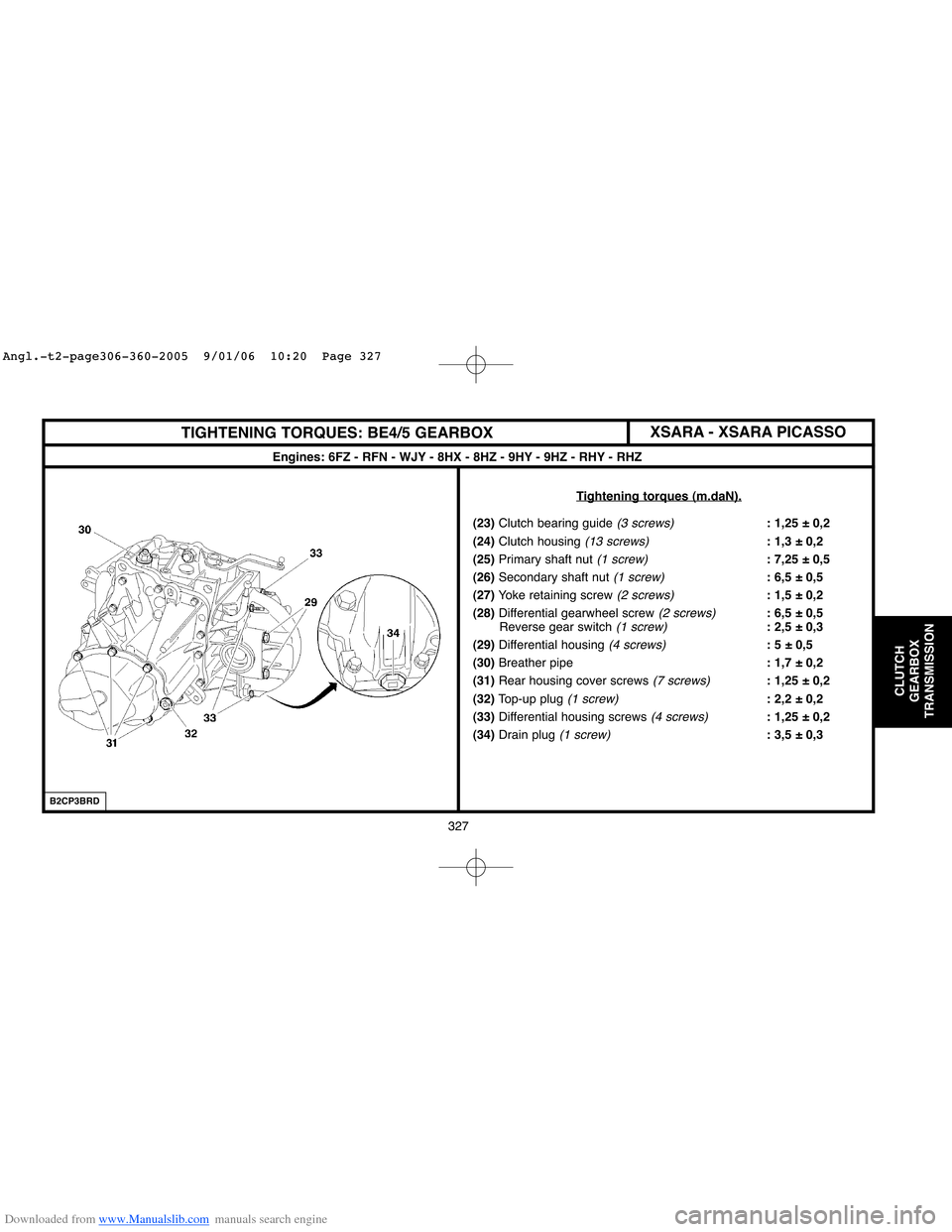
TIGHTENING TORQUES: BE4/5 GEARBOX
Engines: 6FZ - RFN - WJY - 8HX - 8HZ - 9HY - 9HZ - RHY - RHZ
T
ightening torques (m.daN).
(23)Clutch bearing guide (3 screws): 1,25 ± 0,2
(24)Clutch housing
(13 screws): 1,3 ± 0,2
(25)Primary shaft nut
(1 screw): 7,25 ± 0,5
(26)Secondary shaft nut
(1 screw): 6,5 ± 0,5
(27)Yoke retaining screw
(2 screws): 1,5 ± 0,2
(28)Differential gearwheel screw
(2 screws): 6,5 ± 0,5
Reverse gear switch (1 screw): 2,5 ± 0,3
(29)Differential housing
(4 screws): 5 ± 0,5
(30)Breather pipe: 1,7 ± 0,2
(31)Rear housing cover screws
(7 screws): 1,25 ± 0,2
(32)Top-up plug
(1 screw): 2,2 ± 0,2
(33) Differential housing screws
(4 screws): 1,25 ± 0,2
(34)Drain plug
(1 screw): 3,5 ± 0,3
B2CP3BRD
XSARA - XSARA PICASSO
Angl.-t2-page306-360-2005 9/01/06 10:20 Page 327
Page 374 of 462
Downloaded from www.Manualslib.com manuals search engine 368
AXLES
SUSPENSION
STEERING
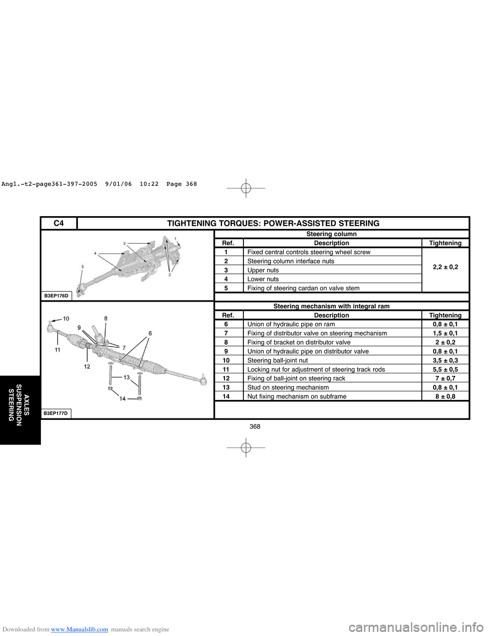
C4TIGHTENING TORQUES: POWER-ASSISTED STEERING
Steering column
Ref. Description Tightening
1Fixed central controls steering wheel screw2,2 ± 0,2
2Steering column interface nuts
3Upper nuts
4Lower nuts
5Fixing of steering cardan on valve stem
Steering mechanism with integral ram
Ref. Description Tightening
6Union of hydraulic pipe on ram0,8 ± 0,1
7Fixing of distributor valve on steering mechanism1,5 ± 0,1
8Fixing of bracket on distributor valve2 ± 0,2
9Union of hydraulic pipe on distributor valve0,8 ± 0,1
10Steering ball-joint nut3,5 ± 0,3
11Locking nut for adjustment of steering track rods5,5 ± 0,5
12Fixing of ball-joint on steering rack7 ± 0,7
13Stud on steering mechanism0,8 ± 0,1
14Nut fixing mechanism on subframe8 ± 0,8
B3EP177D
B3EP176D
2,2 ± 0,2
Angl.-t2-page361-397-2005 9/01/06 10:22 Page 368
Page 377 of 462
![Citroen C4 2005 2.G Owners Manual Downloaded from www.Manualslib.com manuals search engine 371
AXLES
SUSPENSION
STEERING
C4CHECKING THE POWER STEERING ASSISTANCE PRESSURE
Tools.
[1]Pressure gauge: (-).0710.AZ
[2]Checking tube: press Citroen C4 2005 2.G Owners Manual Downloaded from www.Manualslib.com manuals search engine 371
AXLES
SUSPENSION
STEERING
C4CHECKING THE POWER STEERING ASSISTANCE PRESSURE
Tools.
[1]Pressure gauge: (-).0710.AZ
[2]Checking tube: press](/img/9/4138/w960_4138-376.png)
Downloaded from www.Manualslib.com manuals search engine 371
AXLES
SUSPENSION
STEERING
C4CHECKING THE POWER STEERING ASSISTANCE PRESSURE
Tools.
[1]Pressure gauge: (-).0710.AZ
[2]Checking tube: pressure gauge to tap: (-).0710.B1
[3]Checking tube: high pressure pipe to tap: (-).0710.B2
[4]Checking tube: high pressure pump to tap: (-).0710.B3
[5]3-way tap: (-).0710.C
[6]Union: (-).0710.J
[7]Union: (-).0710.K
[8] Plugs for checking valve sealing: (-).0710.H
Precautions to be taken.
Work with care to avoid entry of polluting particles into the circuit.
NOTE:The correct operation of the system requires perfect cleanliness of the fluid and of the
hydraulic components.
Check:
- The level of the power steering fluid.
- The condition of the piping and unions.
Using the tools.
Prepare the checking assembly [1], [2], [3], [4], [5], [6]and [7].
Attach the tool [1].
Remove the front RH wheel, the splash-shield and the screen wash reservoir.
B3EP16CC
B3EP16DC
Angl.-t2-page361-397-2005 9/01/06 10:22 Page 371
Page 378 of 462
Downloaded from www.Manualslib.com manuals search engine 372
AXLES
SUSPENSION
STEERING
CHECKING THE POWER STEERING ASSISTANCE PRESSURE
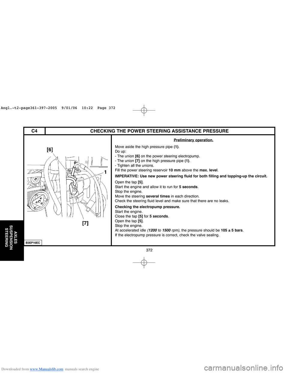
Preliminary operation.
Move aside the high pressure pipe (1).
Do up:
- The union [6]on the power steering electropump.
- The union [7]on the high pressure pipe (1).
- Tighten all the unions.
Fill the power steering reservoir 10 mmabove the max. level.
IMPERATIVE: Use new power steering fluid for both filling and topping-up the circuit.
Open the tap [5].
Start the engine and allow it to run for 5 seconds.
Stop the engine.
Move the steering several timesin each direction.
Check the steering fluid level and make sure that there are no leaks.
Checking the electropump pressure.
Start the engine.
Close the tap [5]for 5 seconds.
Open the tap [5].
Stop the engine.
At accelerated idle
(1200 to 1500rpm), the pressure should be 105 ± 5 bars.
If the electropump pressure is correct, check the valve sealing.
B3EP16EC
C4
Angl.-t2-page361-397-2005 9/01/06 10:22 Page 372
Page 379 of 462
Downloaded from www.Manualslib.com manuals search engine 373
AXLES
SUSPENSION
STEERING
CHECKING THE POWER STEERING ASSISTANCE PRESSURE
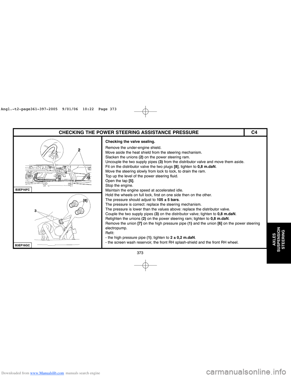
Checking the valve sealing.
Remove the under-engine shield.
Move aside the heat shield from the steering mechanism.
Slacken the unions (2)on the power steering ram.
Uncouple the two supply pipes (3)from the distributor valve and move them aside.
Fit on the distributor valve the two plugs [8], tighten to 0,8 m.daN.
Move the steering slowly from lock to lock, to drain the ram.
Top up the level of the power steering fluid.
Open the tap [5].
Stop the engine.
Maintain the engine speed at accelerated idle.
Hold the wheels on full lock, first on one side then on the other.
The pressure should adjust to 105 ± 5 bars.
The pressure is correct: replace the steering mechanism.
The pressure is lower than the values above: replace the distributor valve.
Couple the two supply pipes (3)on the distributor valve; tighten to 0,8 m.daN.
Retighten the unions (2)on the power steering ram; tighten to 0,8 m.daN.
Remove the union [7]on the high pressure pipe (1)and the union [6]on the power steering
electropump.
Refit:
- the high pressure pipe (1); tighten to 2 ± 0,2 m.daN.
- the screen wash reservoir, the front RH splash-shield and the front RH wheel.
B3EP16FC
B3EP16GC
C4
Angl.-t2-page361-397-2005 9/01/06 10:22 Page 373
Page 392 of 462

Downloaded from www.Manualslib.com manuals search engine 386
AXLES
SUSPENSION
STEERING
TIGHTENING TORQUES: POWER-ASSISTED STEERING
Power steering
XSARA
Tightening torques (m.daN).
(7)Pivot ball-joint nut: 4
(8)Link rod lock nut: 4.5
(9)Ball-joint on steering rack: 6
(10)Fixing on subframe: 5
(11) Hydraulic pipe connection: 2.5
(12)Valve to housing fixing: 1.2
(13)Plunger flange screw: 1.2
(14) Screw fixing the steering ram
to the housing: 5.5
(15)Nut fixing the steering ram
to the yoke: 5.5
B3EP08RD
Angl.-t2-page361-397-2005 9/01/06 10:22 Page 386