circuit Citroen C4 2005 2.G Repair Manual
[x] Cancel search | Manufacturer: CITROEN, Model Year: 2005, Model line: C4, Model: Citroen C4 2005 2.GPages: 462, PDF Size: 10.48 MB
Page 310 of 462
![Citroen C4 2005 2.G Repair Manual Downloaded from www.Manualslib.com manuals search engine 304
INJECTION
CHECKS: EXHAUST GASES RECYCLING CIRCUIT
Tool.
[1]Manual vacuum pump: FACOM DA 16
IMPERATIVE: Respect the safety and cleanliness r Citroen C4 2005 2.G Repair Manual Downloaded from www.Manualslib.com manuals search engine 304
INJECTION
CHECKS: EXHAUST GASES RECYCLING CIRCUIT
Tool.
[1]Manual vacuum pump: FACOM DA 16
IMPERATIVE: Respect the safety and cleanliness r](/img/9/4138/w960_4138-309.png)
Downloaded from www.Manualslib.com manuals search engine 304
INJECTION
CHECKS: EXHAUST GASES RECYCLING CIRCUIT
Tool.
[1]Manual vacuum pump: FACOM DA 16
IMPERATIVE: Respect the safety and cleanliness requirements.
EGR valve.
Connect the tool [1]to the capsule union (1).
Apply, several times in succession, a vacuum of approx. 0.6 barto activate the rod "a".
In abrupt reaction to the vacuum, the valve should close on its seating with a clicking noise.
Exhaust gas reycling (EGR) electrovalve.
Check, not under load, between the electrovalve (2)and the EGR valve (1).
Connect the tool [1]between the electrovalve (2)and the capsule (1).
Compare readings with the values in the table below.
Engine speed (rpm) Vacuum value
780 0,5 bar
2500 0 bar
B1HP12GD
Engines: RHY - RHZ
XSARA PICASSO
Angl.-t2-page283-305-2005 9/01/06 10:18 Page 304
Page 323 of 462
Downloaded from www.Manualslib.com manuals search engine 317
CLUTCH
GEARBOX
TRANSMISSION
HYDRAULIC CLUTCH CONTROL: CHECKS AND ADJUSTMENTS
B2BP04XC
IMPERATIVE: Use only new brake brake fluid that is not emulsified, avoid any
ingress of impurities into the hydraulic circuit.
IMPERATIVE: Do not use automatic bleeding equipment
(risk of the brake fluid
emulsifying in the hydraulic circuit).
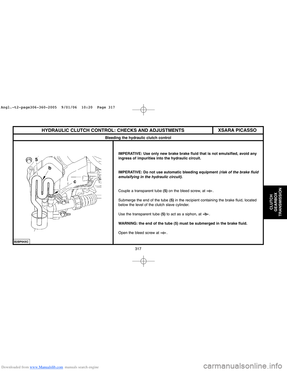
Couple a transparent tube (5)on the bleed screw, at «c».
Submerge the end of the tube (5)in the recipient containing the brake fluid, located
below the level of the clutch slave cylinder.
Use the transparent tube (5) to act as a siphon, at «b».
WARNING: the end of the tube (5) must be submerged in the brake fluid.
Open the bleed screw at «c».
XSARA PICASSO
Bleeding the hydraulic clutch control
Angl.-t2-page306-360-2005 9/01/06 10:20 Page 317
Page 352 of 462
Downloaded from www.Manualslib.com manuals search engine 346
CLUTCH
GEARBOX
TRANSMISSION
RECOMMENDATIONS/PRECAUTIONS : AL4 AUTOMATIC GEARBOX
Procedure for initialising the automatic gearbox ECU
Downloading.
Updating the gearbox ECU by downloading:
- Follow the procedure using the diagnostic tool.
The downloading operation enables the automatic gearbox to be
updated, or adapted to an evolution of the engine ECU.
Before commencing the downloading, take the value of the oil usage
counter present in the automatic gearbox ECU.
After the downloading operation, carry out the following:
- A clearing of faults.
- An initialisation of the auto-adaptives.
- A writing of the value of the oil usage counter previously read.
- A road test.
ESSENTIAL: Every update of the automatic gearbox ECU should
be accompanied by an update of the engine ECU.Updating the value of the oil usage counter.
Using PROXIA.
Access to reading and recording of the oil counter is via the menu:
- «Configuration
(integrated circuit button)/Oil counter».
Adjustment of the oil counter value is done in incremental steps of
2750 units.
Using LEXIA.
Access to reading and recording of the oil counter is via the menu:
- «Oil counter».
Adjustment of the oil counter value is done by entering directly
the 5 figuresof the oil counter.
Angl.-t2-page306-360-2005 9/01/06 10:20 Page 346
Page 377 of 462
![Citroen C4 2005 2.G Repair Manual Downloaded from www.Manualslib.com manuals search engine 371
AXLES
SUSPENSION
STEERING
C4CHECKING THE POWER STEERING ASSISTANCE PRESSURE
Tools.
[1]Pressure gauge: (-).0710.AZ
[2]Checking tube: press Citroen C4 2005 2.G Repair Manual Downloaded from www.Manualslib.com manuals search engine 371
AXLES
SUSPENSION
STEERING
C4CHECKING THE POWER STEERING ASSISTANCE PRESSURE
Tools.
[1]Pressure gauge: (-).0710.AZ
[2]Checking tube: press](/img/9/4138/w960_4138-376.png)
Downloaded from www.Manualslib.com manuals search engine 371
AXLES
SUSPENSION
STEERING
C4CHECKING THE POWER STEERING ASSISTANCE PRESSURE
Tools.
[1]Pressure gauge: (-).0710.AZ
[2]Checking tube: pressure gauge to tap: (-).0710.B1
[3]Checking tube: high pressure pipe to tap: (-).0710.B2
[4]Checking tube: high pressure pump to tap: (-).0710.B3
[5]3-way tap: (-).0710.C
[6]Union: (-).0710.J
[7]Union: (-).0710.K
[8] Plugs for checking valve sealing: (-).0710.H
Precautions to be taken.
Work with care to avoid entry of polluting particles into the circuit.
NOTE:The correct operation of the system requires perfect cleanliness of the fluid and of the
hydraulic components.
Check:
- The level of the power steering fluid.
- The condition of the piping and unions.
Using the tools.
Prepare the checking assembly [1], [2], [3], [4], [5], [6]and [7].
Attach the tool [1].
Remove the front RH wheel, the splash-shield and the screen wash reservoir.
B3EP16CC
B3EP16DC
Angl.-t2-page361-397-2005 9/01/06 10:22 Page 371
Page 378 of 462
Downloaded from www.Manualslib.com manuals search engine 372
AXLES
SUSPENSION
STEERING
CHECKING THE POWER STEERING ASSISTANCE PRESSURE
Preliminary operation.
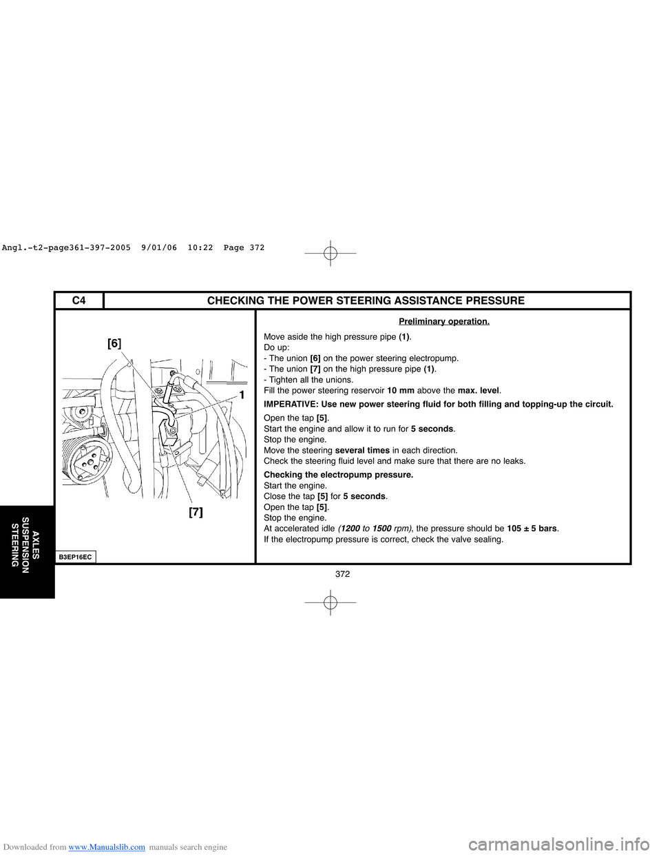
Move aside the high pressure pipe (1).
Do up:
- The union [6]on the power steering electropump.
- The union [7]on the high pressure pipe (1).
- Tighten all the unions.
Fill the power steering reservoir 10 mmabove the max. level.
IMPERATIVE: Use new power steering fluid for both filling and topping-up the circuit.
Open the tap [5].
Start the engine and allow it to run for 5 seconds.
Stop the engine.
Move the steering several timesin each direction.
Check the steering fluid level and make sure that there are no leaks.
Checking the electropump pressure.
Start the engine.
Close the tap [5]for 5 seconds.
Open the tap [5].
Stop the engine.
At accelerated idle
(1200 to 1500rpm), the pressure should be 105 ± 5 bars.
If the electropump pressure is correct, check the valve sealing.
B3EP16EC
C4
Angl.-t2-page361-397-2005 9/01/06 10:22 Page 372
Page 380 of 462
Downloaded from www.Manualslib.com manuals search engine AXLES
SUSPENSION
STEERING
CHECKING THE POWER STEERING ASSISTANCE PRESSURE
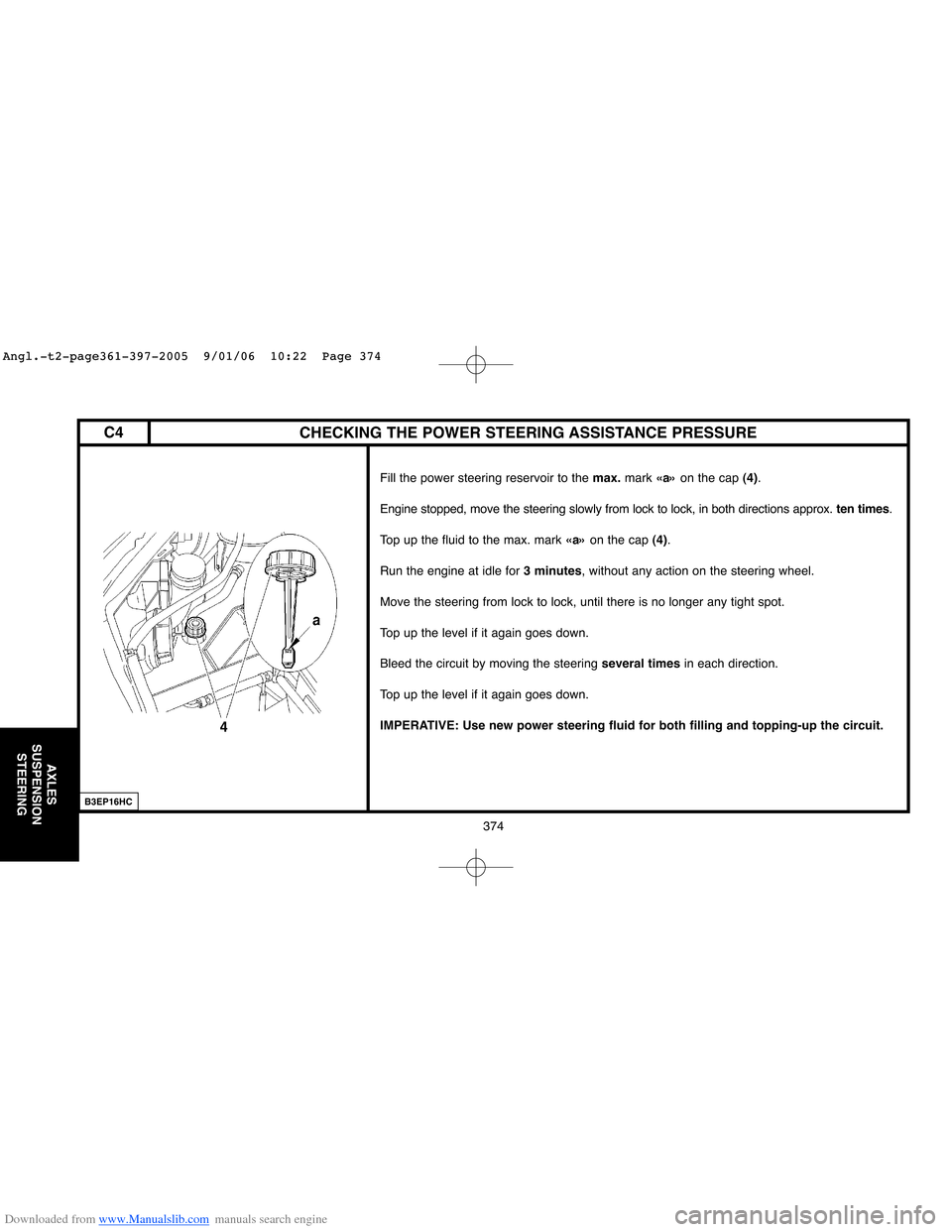
Fill the power steering reservoir to the max.mark «a»on the cap (4).
Engine stopped, move the steering slowly from lock to lock, in both directions approx. ten times.
Top up the fluid to the max. mark «a»on the cap (4).
Run the engine at idle for 3 minutes, without any action on the steering wheel.
Move the steering from lock to lock, until there is no longer any tight spot.
Top up the level if it again goes down.
Bleed the circuit by moving the steering several timesin each direction.
Top up the level if it again goes down.
IMPERATIVE: Use new power steering fluid for both filling and topping-up the circuit.
B3EP16HC
374
C4
Angl.-t2-page361-397-2005 9/01/06 10:22 Page 374
Page 393 of 462
Downloaded from www.Manualslib.com manuals search engine 387
AXLES
SUSPENSION
STEERING
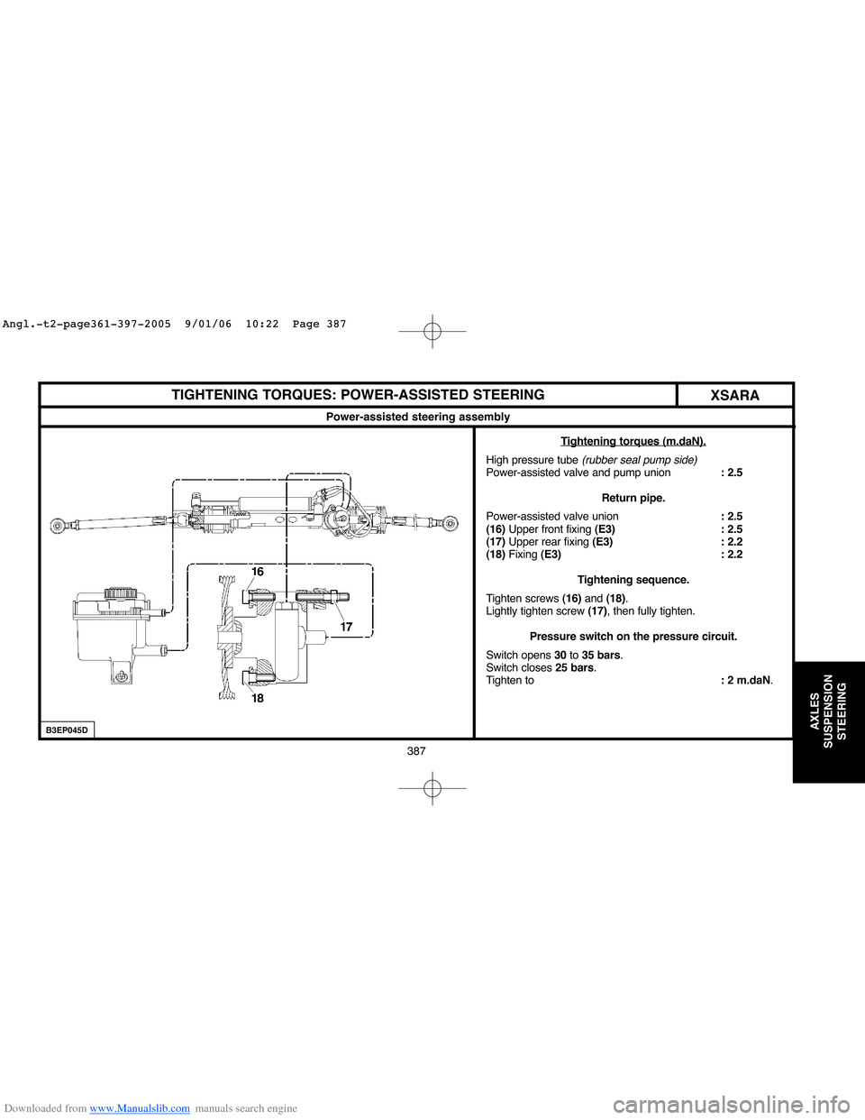
TIGHTENING TORQUES: POWER-ASSISTED STEERING
XSARA
Power-assisted steering assembly
T
ightening torques (m.daN).
High pressure tube (rubber seal pump side)Power-assisted valve and pump union: 2.5
Return pipe.
Power-assisted valve union: 2.5
(16)Upper front fixing (E3) : 2.5
(17)Upper rear fixing (E3) : 2.2
(18)Fixing (E3) : 2.2
Tightening sequence.
Tighten screws (16) and (18).
Lightly tighten screw (17), then fully tighten.
Pressure switch on the pressure circuit.
Switch opens 30to 35 bars.
Switch closes 25 bars.
Tighten to: 2 m.daN.
B3EP045D
Angl.-t2-page361-397-2005 9/01/06 10:22 Page 387
Page 406 of 462
Downloaded from www.Manualslib.com manuals search engine B3FP7E1D
BRAKE SPECIFICATIONS
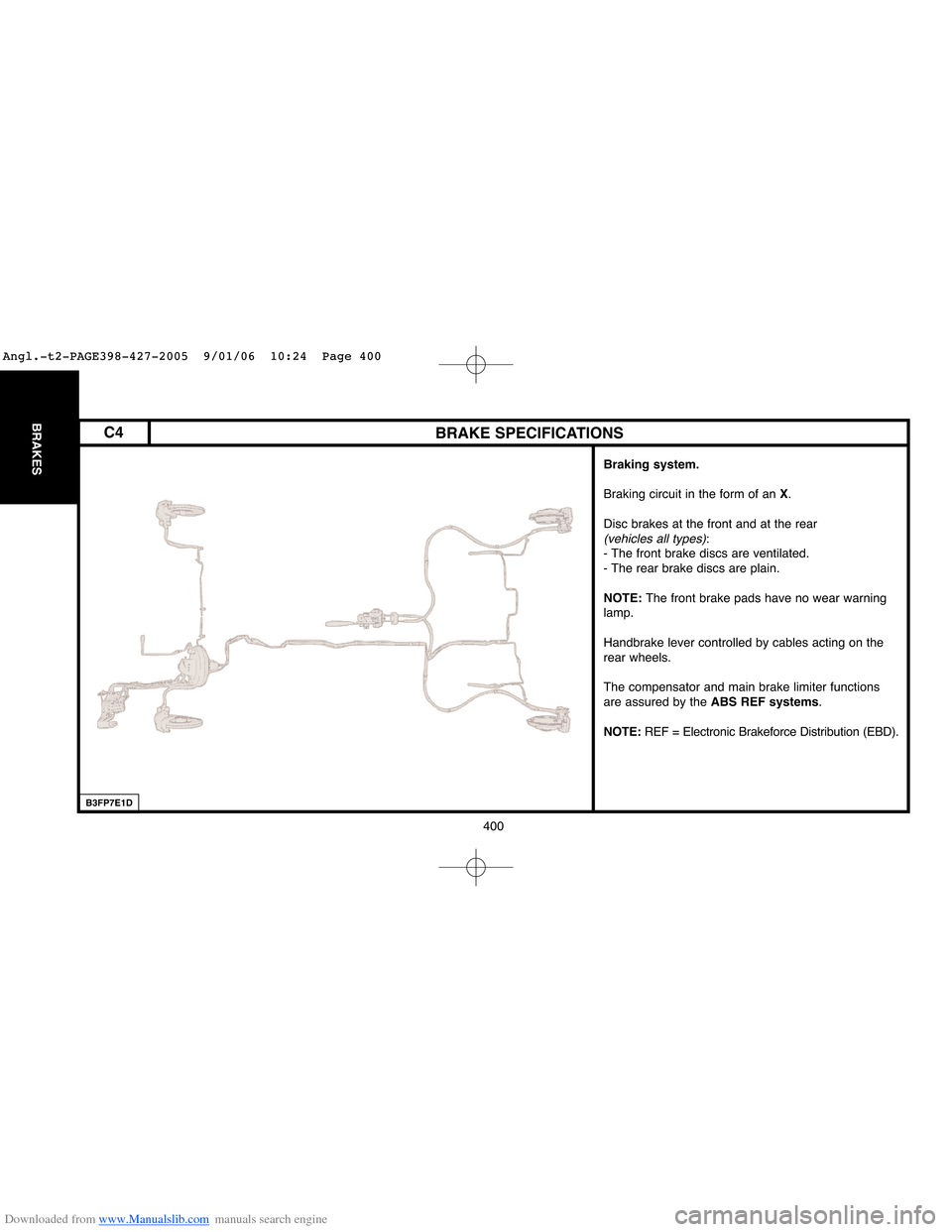
Braking system.
Braking circuit in the form of an X.
Disc brakes at the front and at the rear
(vehicles all types):
- The front brake discs are ventilated.
- The rear brake discs are plain.
NOTE: The front brake pads have no wear warning
lamp.
Handbrake lever controlled by cables acting on the
rear wheels.
The compensator and main brake limiter functions
are assured by the ABS REF systems.
NOTE:REF = Electronic Brakeforce Distribution (EBD).
400
BRAKESC4
Angl.-t2-PAGE398-427-2005 9/01/06 10:24 Page 400
Page 412 of 462
![Citroen C4 2005 2.G Repair Manual Downloaded from www.Manualslib.com manuals search engine 406
BRAKES
B3FP7EQC
BLEEDING AND FILLING THE BRAKING SYSTEM
Tools.
[1]Bleeding apparatus: «LURO» or similar
[2]LEXIA diagnostic tool: 4171-T
Citroen C4 2005 2.G Repair Manual Downloaded from www.Manualslib.com manuals search engine 406
BRAKES
B3FP7EQC
BLEEDING AND FILLING THE BRAKING SYSTEM
Tools.
[1]Bleeding apparatus: «LURO» or similar
[2]LEXIA diagnostic tool: 4171-T](/img/9/4138/w960_4138-411.png)
Downloaded from www.Manualslib.com manuals search engine 406
BRAKES
B3FP7EQC
BLEEDING AND FILLING THE BRAKING SYSTEM
Tools.
[1]Bleeding apparatus: «LURO» or similar
[2]LEXIA diagnostic tool: 4171-T
[3]PROXIA diagnostic tool: 4165-T
NOTE:Bleeding of the secondary braking circuit is done with the aid of diagnostic tools [2]and [3].
Draining of the brake fluid reservoir.
Remove the screws (3)and the battery tray (2).
Remove the filter of the brake fluid reservoir (4).
Drain the brake fluid reservoir (4)to the maximum extent
(if necessary, use a clean syringe).
Remove the screws (1).
Uncouple the clickfit union at «a».
Remove the brake fluid reservoir (4).
C4
Angl.-t2-PAGE398-427-2005 9/01/06 10:24 Page 406
Page 414 of 462
Downloaded from www.Manualslib.com manuals search engine 408
BRAKES
B3FP7EUC
BLEEDING AND FILLING THE BRAKING SYSTEM
Filling the braking circuit.
WARNING: Use only the approved and recommended hydraulic fluids.
IMPERATIVE: Only use new brake fluid that has not emulsified; avoid any introduction of
impurities into the hydraulic circuit.
Fill the brake fluid reservoir (4).
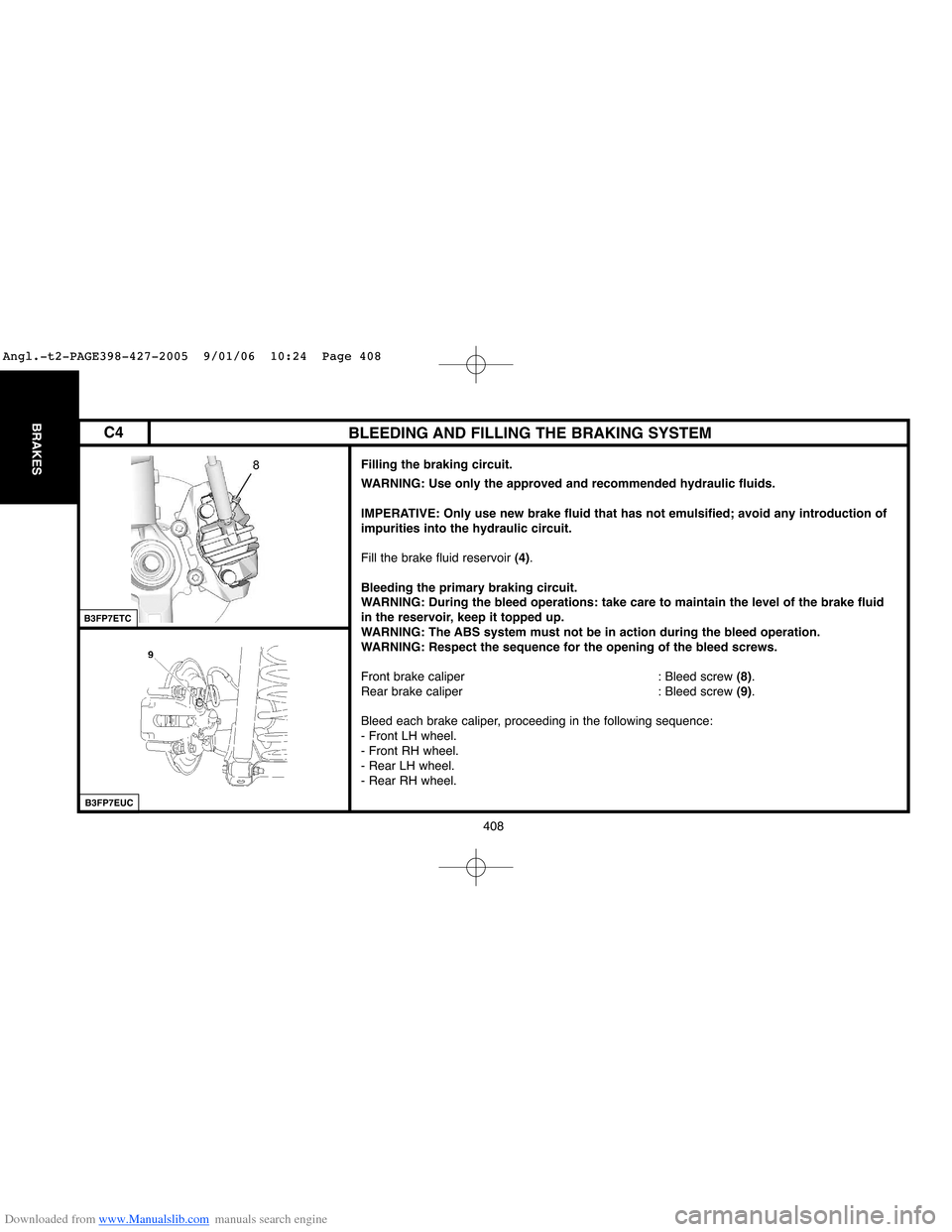
Bleeding the primary braking circuit.
WARNING: During the bleed operations: take care to maintain the level of the brake fluid
in the reservoir, keep it topped up.
WARNING: The ABS system must not be in action during the bleed operation.
WARNING: Respect the sequence for the opening of the bleed screws.
Front brake caliper : Bleed screw (8).
Rear brake caliper : Bleed screw (9).
Bleed each brake caliper, proceeding in the following sequence:
- Front LH wheel.
- Front RH wheel.
- Rear LH wheel.
- Rear RH wheel.
B3FP7ETC
C4
Angl.-t2-PAGE398-427-2005 9/01/06 10:24 Page 408