engine CITROEN C4 2018 Manual PDF
[x] Cancel search | Manufacturer: CITROEN, Model Year: 2018, Model line: C4, Model: CITROEN C4 2018Pages: 317, PDF Size: 9.31 MB
Page 189 of 317
187
C4-cactus_en_Chap08_En-cas-de-panne_ed01-2016
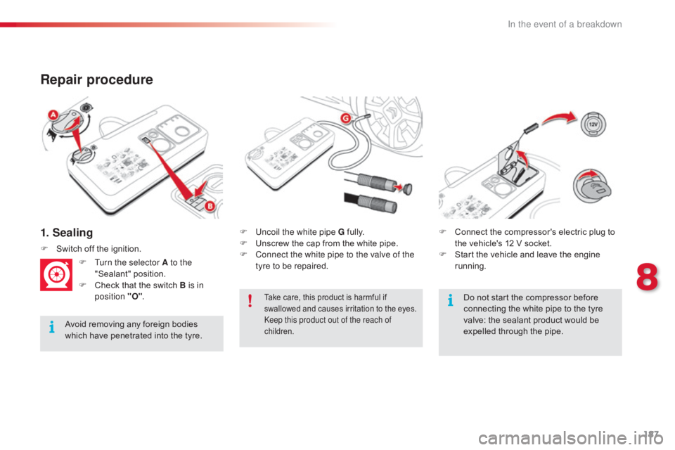
1. Sealing
Repair procedure
Avoidô removingô anyô foreignô bodiesô which ô have ô penetrated ô into ô the ô tyre.F
U
ncoil the white pipe G ô
f
ully.
F ô
U
nscrew ô the ô cap ô from ô the ô white ô pipe.
F
C
onnect the white pipe to the valve of the
tyre ô to ô be ô repaired.
F
ô
S
witch ô off ô the ô ignition.
F
T
urn the selector A to the
"Sealant"
ô p
osition.
F ô
C
heck ô that ô the ô switch ô B is in
position "O" . F ô
C
onnect ô the ô compressor's ô electric ô plug ô to ô
t
he ô vehicle's ô 12 ô V ô socket.
F ô
S
tart ô the ô vehicle ô and ô leave ô the ô engine ô
r
unning.
Takeô care,ô thisô productô isô harmfulô ifô s
wallowed ô and ô causes ô irritation ô to ô the ô eyes.
Keep this product out of the reach of
children.Doô notô startô theô compressorô beforeô c onnecting ô the ô white ô pipe ô to ô the ô tyre ô
v
alve: ô the ô sealant ô product ô would ô be ô
e
xpelled ô through ô the ô pipe.
8
In the event of a breakdown
Page 192 of 317
190
C4-cactus_en_Chap08_En-cas-de-panne_ed01-2016
Checking tyre pressures / inflating accessories
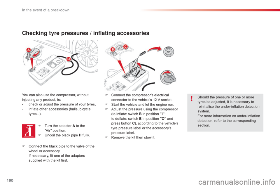
Youô canô alsoô useô theô compressor,ô withoutô injecting ô any ô product, ô to:
-
ô
c
heck ô or ô adjust ô the ô pressure ô of ô your ô tyres,
-
i
nflate other accessories (balls, bicycle
tyres...).
F
T
urn the selector A to the
"Air"ô position.
F
ô
U
ncoil ô the ô black ô pipe ô H ô
f
ully.F
ô C onnect ô the ô compressor's ô electrical ô
c
onnector ô to ô the ô vehicle's ô 12 ô V ô socket.
F
ô
S
tart ô the ô vehicle ô and ô let ô the ô engine ô run.
F
ô
A
djust ô the ô pressure ô using ô the ô compressor ô
(
to ô inflate: ô switch ô B in position "I";
ô
t
oô deflate: ô switch ô B in position "O" and
press button C ),
ô according ô to ô the ô vehicle's ô
t
yre ô pressure ô label ô or ô the ô accessory's ô
p
ressure ô label.
F
ô
R
emove ô the ô kit ô then ô stow ô it.Should
ô the ô pressure ô of ô one ô or ô more ô
t
yres ô be ô adjusted, ô it ô is ô necessary ô to ô
r
einitialise the under-inflation detection
system.
For
ô more ô information ô on ô under-inflation ô
d
etection, ô refer ô to ô the ô corresponding ô
s
ection.
F
ô
C
onnect ô the ô black ô pipe ô to ô the ô valve ô of ô the ô
w
heel ô or ô accessory.
I
f necessary, fit one of the adaptors
supplied
ô with ô the ô kit ô first.
In the event of a breakdown
Page 194 of 317
192
C4-cactus_en_Chap08_En-cas-de-panne_ed01-2016
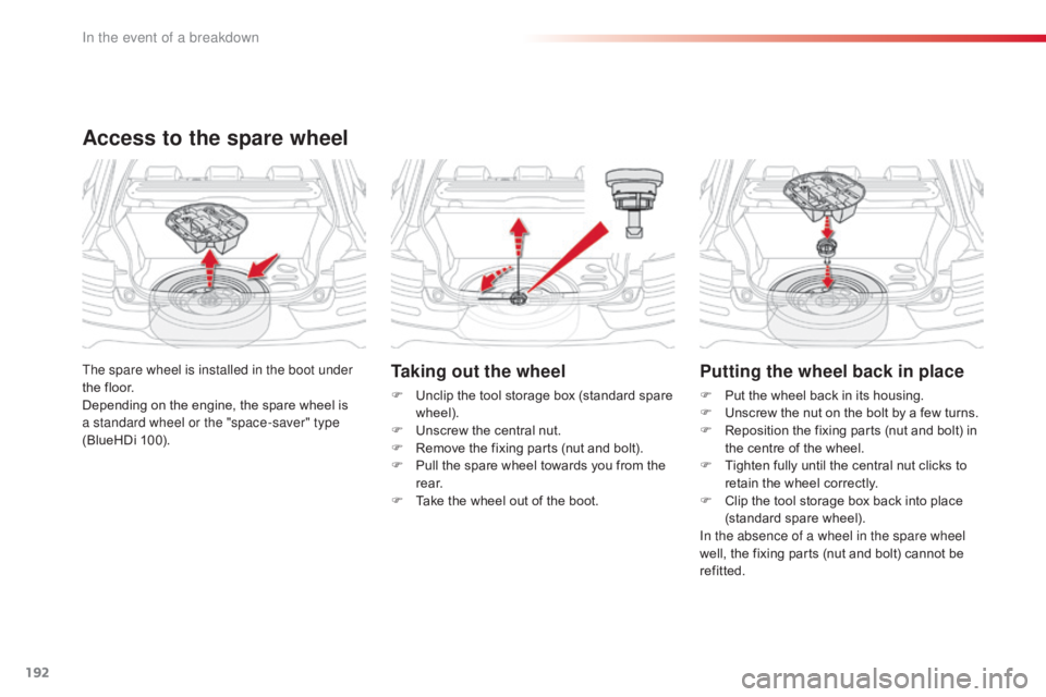
Taking out the wheel
Fô Unclipô the ô tool ô storage ô box ô (standard ô spare ô w
heel).
F
ô
U
nscrew ô the ô central ô nut.
F
ô
R
emove ô the ô fixing ô parts ô (nut ô and ô bolt).
F
ô
P
ull ô the ô spare ô wheel ô towards ô you ô from ô the ô
r
e a r.
F
ô
T
ake ô the ô wheel ô out ô of ô the ô boot.
The spare wheel is installed in the boot under
the
ô
floor.
Depending
ô
on
ô
the
ô
engine,
ô
the
ô
spare
ô
wheel
ô
is
ô
a s
tandard wheel or the "space-saver" type
(BlueHDi
ô
100).
Access to the spare wheel
Putting the wheel back in place
Fô Put ô the ô wheel ô back ô in ô its ô housing.
F ô U nscrew ô the ô nut ô on ô the ô bolt ô by ô a ô few ô turns.
F
ô
R
eposition ô the ô fixing ô parts ô (nut ô and ô bolt) ô in ô
t
he ô centre ô of ô the ô wheel.
F
ô
T
ighten ô fully ô until ô the ô central ô nut ô clicks ô to ô
r
etain ô the ô wheel ô correctly.
F
ô
C
lip ô the ô tool ô storage ô box ô back ô into ô place ô
(
standard
ô spar
e
ô w
heel).
In the absence of a wheel in the spare wheel
well,
ô the ô fixing ô parts ô (nut ô and ô bolt) ô cannot ô be ô
r
efitted.
In the event of a breakdown
Page 212 of 317
210
C4-cactus_en_Chap08_En-cas-de-panne_ed01-2016
Engine compartment fuses
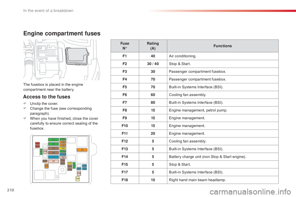
Access to the fuses
Fô Unclipô the ô cover.
F ô C hange ô the ô fuse ô (see ô corresponding ô
par
agraph).
F
W
hen you have finished, close the cover
carefully
ô to ô ensure ô correct ô sealing ô of ô the ô
f
usebox. Fuse
Nô¯ Rating
(A) Functions
F1 40Air
ô c
onditioning.
F2 30 / 40Stop ô & ô Start.
F3 30Passenger
ô c
ompartment
ô f
usebox.
F4 70Passenger
ô c
ompartment
ô f
usebox.
F5 70Built-in ô Systems ô Inter face ô (BSI).
F6 60Cooling ô fan ô assembly.
F7 80Built-in ô Systems ô Inter face ô (BSI).
F8 15Engine
ô management, ô petrol ô pump.
F9 15Engine
ô m
anagement.
F10 15Engine
ô m
anagement.
F11 20Engine
ô m
anagement.
F12 5Cooling
ô fan ô assembly.
F13 5Built-in
ô Systems ô Inter face ô (BSI).
F14 5Battery
ô charge ô unit ô (non ô Stop ô & ô Start ô engine).
F15 5Stop
ô & ô Start.
F17 5Built-in
ô Systems ô Inter face ô (BSI).
F18 10Right
ô hand ô main ô beam ô headlamp.
The
ô fusebox ô is ô placed ô in ô the ô engine ô
c
ompartment ô near ô the ô battery.
In the event of a breakdown
Page 213 of 317
211
C4-cactus_en_Chap08_En-cas-de-panne_ed01-2016
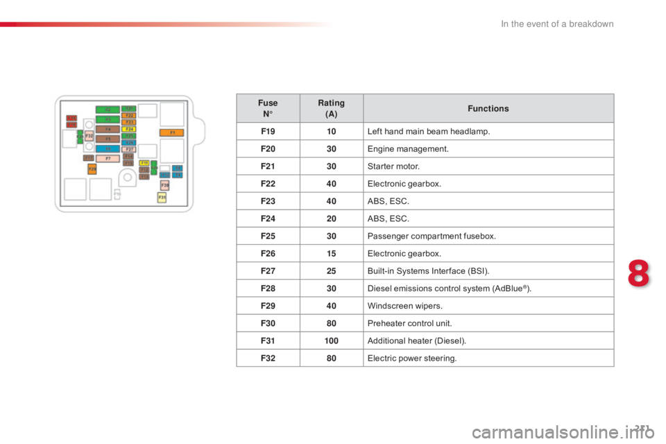
FuseNô¯ Rating
(A) Functions
F19 10Left
ô hand ô main ô beam ô headlamp.
F20 30Engine
ô m
anagement.
F21 30Starter
ô motor.
F22 40Electronic
ô g
earbox.
F23 40ABS,
ô ESC.
F24 20ABS,
ô ESC.
F25 30Passenger
ô c
ompartment
ô f
usebox.
F26 15Electronic
ô g
earbox.
F27 25Built-in
ô Systems ô Inter face ô (BSI).
F28 30Diesel
ô emissions ô control ô system ô (AdBlue
ôÛ).
F29 40Windscreen
ô w
ipers.
F30 80Preheater
ô
control
ô
unit.
F31 100Additional
ô hea
ter
ô (
Diesel).
F32 80Electric
ô
power
ô
steering.
8
In the event of a breakdown
Page 214 of 317
212
C4-cactus_en_Chap08_En-cas-de-panne_ed01-2016
12 V battery
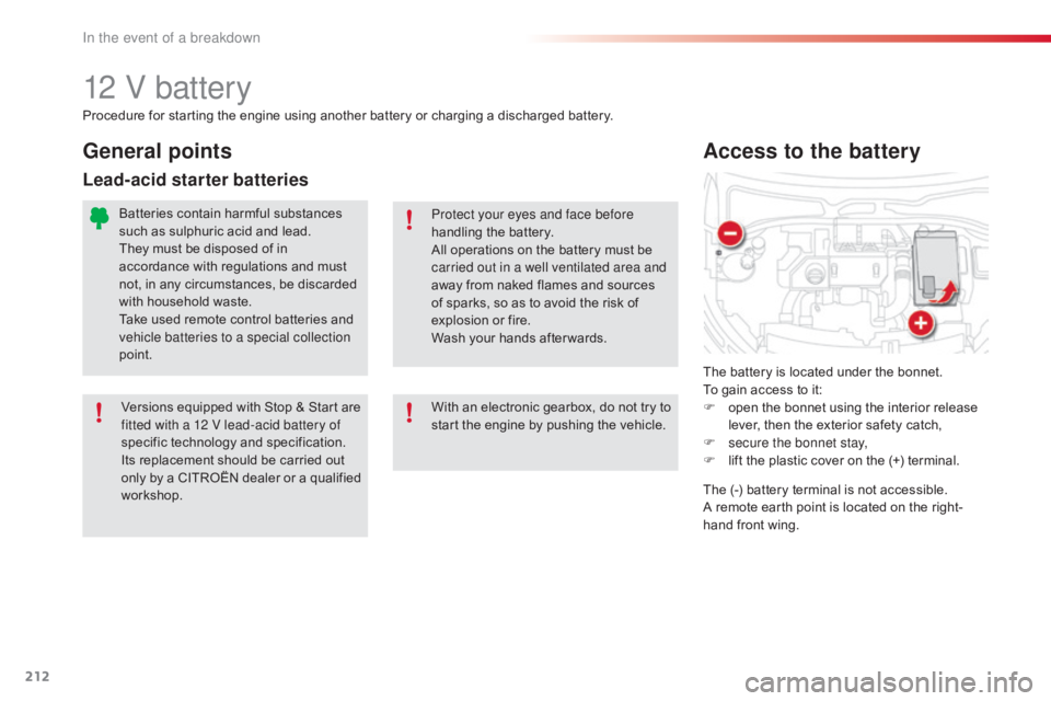
Theô batteryô isô locatedô underô theô bonnet.
T o ô gain ô access ô to ô it:
F
ô
o
pen ô the ô bonnet ô using ô the ô interior ô release ô
l
ever, ô then ô the ô exterior ô safety ô catch,
F
s
ecure the bonnet stay,
F
ô
l
ift ô the ô plastic ô cover ô on ô the ô (+) ô terminal.
Access to the battery
Procedureô forô startingô theô engineô usingô anotherô batteryô orô chargingô aô dischargedô battery.
P rotect your eyes and face before
handling
ô the ô battery.
All
ô operations ô on ô the ô battery ô must ô be ô
c
arried out in a well ventilated area and
away
ô from ô naked ô flames ô and ô sources ô
o
f ô sparks, ô so ô as ô to ô avoid ô the ô risk ô of ô
e
xplosion ô or ô fire.
Wash
ô your ô hands ô after wards.
Versions
ô equipped ô with ô Stop ô & ô Start ô are ô
f
itted with a 12 V lead-acid battery of
specific
ô t
echnology
ô a
nd
ô s
pecification.
Its
ô replacement ô should ô be ô carried ô out ô
o
nly
ô
by
ô
a
ô
CITROûN
ô
dealer
ô
or
ô
a
ô
qualified
ô w
orkshop.
General points
Lead-acid starter batteries
Batteriesô containô harmfulô substancesô such ô as ô sulphuric ô acid ô and ô lead.
They
ô must ô be ô disposed ô of ô in ô
a
ccordance ô with ô regulations ô and ô must ô
n
ot, ô in ô any ô circumstances, ô be ô discarded ô
w
ith ô household ô waste.
Take
ô used ô remote ô control ô batteries ô and ô
v
ehicle batteries to a special collection
point.
With
ô an ô electronic ô gearbox, ô do ô not ô try ô to ô
s
tart ô the ô engine ô by ô pushing ô the ô vehicle.The
ô (-) ô battery ô terminal ô is ô not ô accessible.
A
ô remote ô earth ô point ô is ô located ô on ô the ô right-
hand
ô front ô wing.
In the event of a breakdown
Page 215 of 317
213
C4-cactus_en_Chap08_En-cas-de-panne_ed01-2016
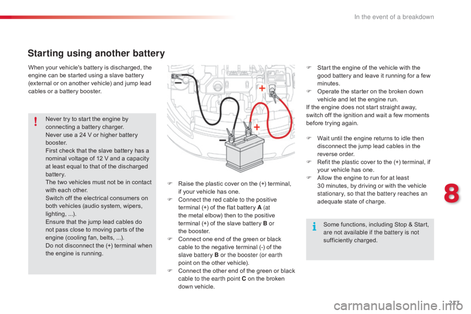
Whenô yourô vehicle'sô batteryô isô discharged,ô theô engine ô can ô be ô started ô using ô a ô slave ô battery ô
(
external ô or ô on ô another ô vehicle) ô and ô jump ô lead ô
c
ables ô or ô a ô battery ô booster.
Starting using another battery
Fô Raiseô the ô plastic ô cover ô on ô the ô (+) ô terminal, ô i
f ô your ô vehicle ô has ô one.
F
C
onnect the red cable to the positive
terminal
ô (+) ô of ô the ô flat ô battery ô A (at
the
ô metal ô elbow) ô then ô to ô the ô positive ô
t
erminalô (+) ô of ô the ô slave ô battery ô B or
theô booster.
F
ô
C
onnect ô one ô end ô of ô the ô green ô or ô black ô
c
able ô to ô the ô negative ô terminal ô (-) ô of ô the ô
s
lave battery B or the booster (or earth
point
ô on ô the ô other ô vehicle).
F
ô
C
onnect ô
t
he ô
o
ther ô
e
nd ô
o
f ô
t
he ô
g
reen ô
o
r ô
b
lack ô
c
able to the earth point C ô on ô the ô broken ô
d
own ô vehicle. F
ô
S
tart ô the ô engine ô of ô the ô vehicle ô with ô the ô
g
ood ô battery ô and ô leave ô it ô running ô for ô a ô few ô
m
inutes.
F ô
O
perate ô the ô starter ô on ô the ô broken ô down ô
v
ehicle ô and ô let ô the ô engine ô run.
If ô the ô engine ô does ô not ô start ô straight ô away, ô
s
witch ô off ô the ô ignition ô and ô wait ô a ô few ô moments ô
b
efore ô trying ô again.
Never
ô
try
ô
to
ô
start
ô
the
ô
engine
ô
by
ô
c
onnecting
ô
a
ô
battery
ô
charger.
Never
ô
use
ô
a
ô
24
ô
V
ô
or
ô
higher
ô
battery
ô
b
o o s t e r.
First
ô
check
ô
that
ô
the
ô
slave
ô
battery
ô
has
ô
a
ô
n
ominal
ô
voltage
ô
of
ô
12
ô
V
ô
and
ô
a
ô
capacity
ô
a
t
ô
least
ô
equal
ô
to
ô
that
ô
of
ô
the
ô
discharged
ô
b
attery.
The
ô
two
ô
vehicles
ô
must
ô
not
ô
be
ô
in
ô
contact
ô w
ith
ô
each
ô
other.
Switch
ô
off
ô
the
ô
electrical
ô
consumers
ô
on
ô
b
oth
ô
vehicles
ô
(audio
ô
system,
ô
wipers,
ô
l
ighting,ô ...).
Ensure
ô
that
ô
the
ô
jump
ô
lead
ô
cables
ô
do
ô
n
ot
ô
pass
ô
close
ô
to
ô
moving
ô
parts
ô
of
ô
the
ô
e
ngine
ô
(cooling
ô
fan,
ô
belts,ô ...).
Do
ô
not
ô
disconnect
ô
the
ô
(+)
ô
terminal
ô
when
ô
t
he
ô
engine
ô
is
ô
running. F
ô
W
ait ô until ô the ô engine ô returns ô to ô idle ô then ô
d
isconnect ô the ô jump ô lead ô cables ô in ô the ô
r
everse
ô o
rder.
F ô
R
efit ô the ô plastic ô cover ô to ô the ô (+) ô terminal, ô if ô
y
our ô vehicle ô has ô one.
F ô A llow ô the ô engine ô to ô run ô for ô at ô least ô 3
0ô minutes, ô by ô driving ô or ô with ô the ô vehicle ô
s
tationary, so that the battery reaches an
adequate
ô state ô of ô charge.
Some
ô functions, ô including ô Stop ô & ô Start, ô
a
re not available if the battery is not
sufficiently
ô c
harged.
8
In the event of a breakdown
Page 217 of 317
215
C4-cactus_en_Chap08_En-cas-de-panne_ed01-2016
Doô notô forceô theô leverô asô lockingô willô not ô be ô possible ô if ô the ô clamp ô is ô not ô
p
ositioned ô correctly; ô start ô the ô procedure ô
ag
ain.
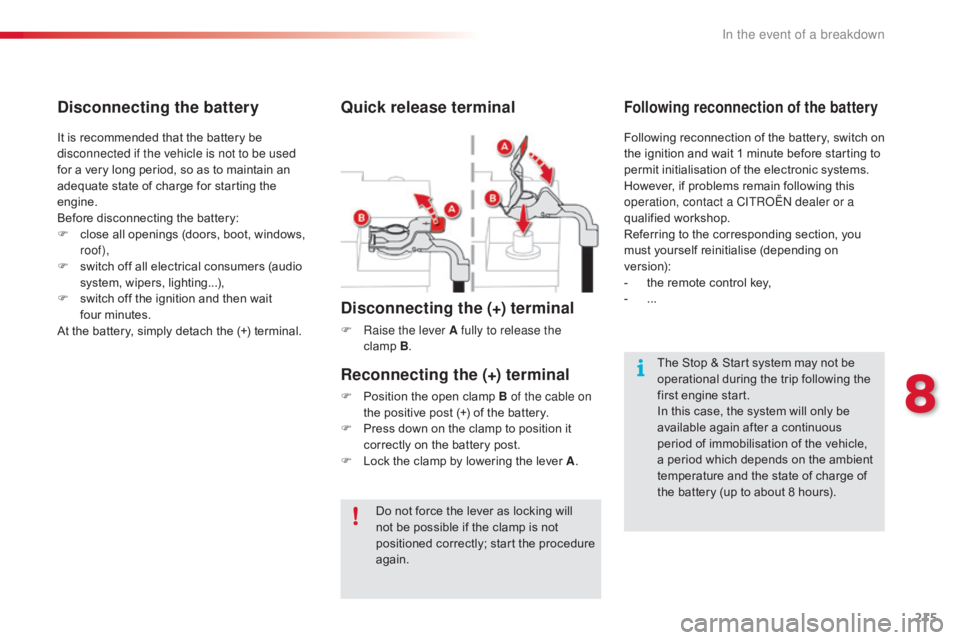
Quick release terminal
Disconnecting the (+) terminal
F Raise the lever A fully to release the clampô B.
The
ô Stop ô & ô Start ô system ô may ô not ô be ô
o
perational ô during ô the ô trip ô following ô the ô
f
irst ô engine ô start.
In
ô this ô case, ô the ô system ô will ô only ô be ô
a
vailable ô again ô after ô a ô continuous ô
p
eriod ô of ô immobilisation ô of ô the ô vehicle, ô
a
ô period ô which ô depends ô on ô the ô ambient ô
t
emperature ô and ô the ô state ô of ô charge ô of ô
t
he ô battery ô (up ô to ô about ô 8 ô hours).
It
ô
is
ô
recommended
ô
that
ô
the
ô
battery
ô
be
ô
d
isconnected if the vehicle is not to be used
for
ô
a
ô
very
ô
long
ô
period,
ô
so
ô
as
ô
to
ô
maintain
ô
an
ô
a
dequate
ô
state
ô
of
ô
charge
ô
for
ô
starting
ô
the
ô
e
ngine.
Before
ô
disconnecting
ô
the
ô
battery:
F
ô
c
lose
ô
all
ô
openings
ô
(doors,
ô
boot,
ô
windows,
ô
r
oof),
F
ô
s
witch
ô
off
ô
all
ô
electrical
ô
consumers
ô
(audio
ô
s
ystem,
ô
wipers,
ô
lighting...),
F
ô
s
witch
ô
off
ô
the
ô
ignition
ô
and
ô
then
ô
wait
ô f
ourô minutes.
At
ô
the
ô
battery,
ô
simply
ô
detach
ô
the
ô
(+)
ô
terminal.
Disconnecting the battery
Followingô reconnectionô ofô theô battery,ô switchô onô t
he ô ignition ô and ô wait ô 1 ô minute ô before ô starting ô to ô
p
ermit ô initialisation ô of ô the ô electronic ô systems. ô
H
owever, ô if ô problems ô remain ô following ô this ô
o
peration, contact a CITROûN dealer or a
qualified
ô w
orkshop.
Referring
ô to ô the ô corresponding ô section, ô you ô
m
ust
ô y
ourself
ô r
einitialise
ô (
depending
ô o
n
ô ve
rsion):
-
ô
t
he ô remote ô control ô key,
-
ô ...
Following reconnection of the battery
Reconnecting the (+) terminal
Fô Position ô the ô open ô clamp ô B of the cable on
the ô positive ô post ô (+) ô of ô the ô battery.
F
ô
P
ress ô down ô on ô the ô clamp ô to ô position ô it ô
c
orrectly ô on ô the ô battery ô post.
F
ô
L
ock ô the ô clamp ô by ô lowering ô the ô lever ô A.
8
In the event of a breakdown
Page 218 of 317
216
C4-cactus_en_Chap08_En-cas-de-panne_ed01-2016
To w i n g
General recommendations
Observeô theô legislationô inô forceô inô yourô country.
E nsure ô that ô the ô weight ô of ô the ô towing ô vehicle ô is ô higher ô than ô that ô of ô the ô towed ô vehicle.
The
ô driver ô must ô remain ô at ô the ô wheel ô of ô the ô towed ô vehicle ô and ô must ô have ô a ô valid ô driving ô licence.
When
ô towing ô a ô vehicle ô with ô all ô four ô wheels ô on ô the ô ground, ô always ô use ô an ô approved ô towing ô arm;
ô r
ope ô and ô straps ô are ô prohibited.
The
ô towing ô vehicle ô must ô move ô off ô gently.
When
ô towing ô a ô vehicle ô with ô the ô engine ô off, ô there ô is ô no ô longer ô any ô power ô assistance ô for ô braking
ô o
r ô steering.
In
ô the ô following ô cases, ô you ô must ô always ô call ô on ô a ô professional ô recovery ô service:
-
ô
v
ehicle ô broken ô down ô on ô a ô motor way ô or ô fast ô road,
-
f
our-wheel drive vehicle,
-
ô
w
hen ô it ô is ô not ô possible ô to ô put ô the ô gearbox ô into ô neutral, ô unlock ô the ô steering, ô or ô release ô the
ô par
king
ô b
rake,
-
ô
t
owing ô with ô only ô two ô wheels ô on ô the ô ground,
-
ô
w
here ô there ô is ô no ô approved ô towing ô arm ô available...
Procedure
ô
for
ô
having
ô
your
ô
vehicle
ô
towed
ô
or
ô
for
ô
towing
ô
another ô vehicle ô using ô a ô removable ô towing ô eye.
The towing eye is stowed under the boot floor,
or
ô
may
ô
be
ô
located
ô
under
ô
the
ô
front
ô
passenger
ô sea
t,ô d
ependingô o
nô v
ersion.
In the event of a breakdown
Page 219 of 317
217
C4-cactus_en_Chap08_En-cas-de-panne_ed01-2016
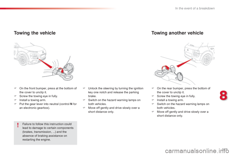
Towing another vehicle
Fô Onô the ô rear ô bumper, ô press ô the ô bottom ô of ô t
he ô cover ô to ô unclip ô it.
F
ô
S
crew ô the ô towing ô eye ô in ô fully.
F
ô
I
nstall ô a ô towing ô arm.
F
ô
S
witch ô on ô the ô hazard ô warning ô lamps ô on ô
b
oth ô vehicles.
F
ô
M
ove ô off ô gently ô and ô drive ô slowly ô over ô a ô
s
hort ô distance ô only.
F
ô O
n
ô
the
ô
front
ô
bumper,
ô
press
ô
at
ô
the
ô
bottom
ô
of
ô t
he
ô
cover
ô
to
ô
unclip
ô
it.
F
ô
S
crew
ô
the
ô
towing
ô
eye
ô
in
ô
fully.
F
ô
I
nstall
ô
a
ô
towing
ô
arm.
F
ô
P
ut
ô
the
ô
gear
ô
lever
ô
into
ô
neutral
ô
(control
ô
N for
an
ô
electronic
ô
gearbox).
Towing the vehicle
Failure to follow this instruction could
lead ô to ô damage ô to ô certain ô components ô
(
brakes, ô transmission,ô ...) ô and ô the ô
a
bsence ô of ô braking ô assistance ô on ô
r
estarting ô the ô engine. F
ô
U
nlock ô the ô steering ô by ô turning ô the ô ignition ô
k
ey ô one ô notch ô and ô release ô the ô parking ô
b
rake.
F ô
S
witch ô on ô the ô hazard ô warning ô lamps ô on ô
b
oth ô vehicles.
F ô
M
ove ô off ô gently ô and ô drive ô slowly ô over ô a ô
s
hort ô distance ô only.
8
In the event of a breakdown