steering Citroen C4 DAG 2014.5 2.G Owner's Guide
[x] Cancel search | Manufacturer: CITROEN, Model Year: 2014.5, Model line: C4 DAG, Model: Citroen C4 DAG 2014.5 2.GPages: 340, PDF Size: 12.89 MB
Page 163 of 340
99
161
C4-2_en_Chap09_conduite_ed01-2014
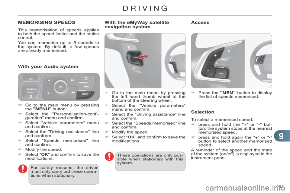
MEMORISING SPEEDS
This memorisation of speeds applies to
both the speed limiter and the cruise
control.
Y
ou
can
memorise
up
to
5
speeds
in
the
system.
By
default,
a
few
speeds
are
already memorised.
F
Press the
"MEM"
button
to
display
the
list of speeds memorised.
Selection
To select a memorised speed:
F
press
and
hold
the
"
+" or "-" but-
ton;
the
system
stops
at
the
nearest
memorised
speed,
F
press
and
hold
again
the
"
+" or "-"
button
to
select
another
memorised
speed.
A
reminder
of
the
speed
and
the
state
of
the
system
(on/of
f)
is
displayed
in
the
instrument
panel.
For
safety
reasons,
the
driver
must
only
carry
out
these
opera
-
tions
when
stationary.
F
Go
to
the
main
menu
by
pressing
the
"MENU"
button:
F
Select
the
"Personalisation-confi
-guration"
menu
and
confirm.
F
Select
"V
ehicle
parameters"
menu
and
confirm.
F
Select
the
"Driving
assistance"
line
and
conform.
F
Select
"Speeds
memorised"
line
and
confirm.
F
Modify
the
speed.
F
Select "
OK"
and
confirm
to
save
the
modifications.
With your Audio system With the eMyWay satellite
navigation system
F Go
to the main menu by pressing the
left hand thumb wheel at the
bottom
of the steering wheel.
F
Select
the
"V
ehicle
parameters"
menu
and confirm.
F
Select
the
"Driving
assistance"
line
and
confirm.
F
Select
the
"Speeds
memorised"
line
and
confirm.
F
Modify
the speed.
F
Select "
OK"
and
confirm
to
save
the
modifications.These operations are only pos
-
sible when stationary with this
system.
Access
DRIVING
Page 164 of 340

99
162
C4-2_en_Chap09_conduite_ed01-2014
The programmed information is grouped together
in the instrument panel screen.
6.
Speed
limiter on / off indication.
7.
Speed
limiter
mode
selection
indica
-
tion.
8.
Programmed
speed value.
9.
Selection
of a memorised speed.
Displays in the instrument panel
S
PEED
LIMITER
The speed limiter cannot, in any circumstances,
replace the need
to
respect
speed
limits,
nor
can
it
replace
the
need
for
vigilance
on
the
part of the driver. The
functions
of
this
system
are
grouped
together
on
the
steering
mounted
controls.
1.
Speed
limiter
mode
selection
wheel.
2.
Programmed
value
decrease
but
-
ton.
3.
Programmed
value
increase
button.
4.
Speed
limiter on / off button.
5.
List
of
memorised
speeds
display
button.
Steering mounted controls
Operation
System which prevents the vehicle from
exceeding the speed programmed
by
the driver.
When
the
programmed
speed
limit
is
reached,
pressing
the
accelerator
ped
-
al
no longer has any effect.
The
speed
limiter
is
switched on
man
-
ually:
it
requires
a
programmed
speed
of
at least 20 mph (30 km/h).
The
speed
limiter
is
switched off
by
manual
operation of the control.
The
programmed
speed
can
be
ex
-
ceeded
temporarily
by
pressing
the
accelerator
firmly
beyond
the
point
of
resistance.
T
o
return
to
the
programmed
speed,
simply
release the accelerator pedal.
The
programmed
speed
remains
in
the
memory
when
the
ignition
is
switched
of
f.
DRIVING
Page 166 of 340
99
164
C4-2_en_Chap09_conduite_ed01-2014
The cruise control system can -
not, in any circumstances, re -
place
the
need
to
respect
speed
limits,
nor
can
it
replace
the
need
for
vigilance
on
the
part
of
the
driver.
You
are
advised
to
keep
your
feet
near the pedals at all times.
CRUISE CONTROL
System which automatically maintains the
speed of the vehicle at the value
programmed
by
the
driver
,
without
any
action
on the accelerator pedal.
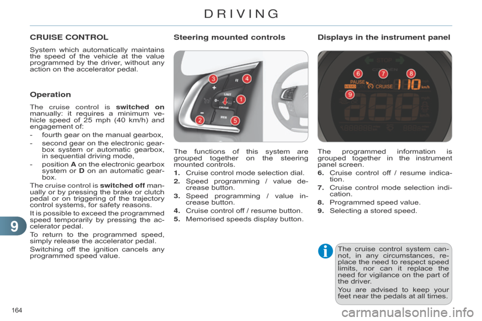
The
functions
of
this
system
are
grouped
together
on
the
steering
mounted
controls.
1.
Cruise
control mode selection dial.
2.
Speed
programming
/
value
de
-
crease
button.
3.
Speed
programming
/
value
in
-
crease
button.
4.
Cruise
control off / resume button.
5.
Memorised
speeds display button.
Steering mounted controls
The programmed information is grouped
together in the instrument
panel
screen.
6.
Cruise
control
of
f
/
resume
indica
-
tion.
7.
Cruise
control
mode
selection
indi
-
cation.
8.
Programmed
speed value.
9.
Selecting
a stored speed.
Displays in the instrument panel
Operation
The cruise control is switched on
manually: it requires a minimum ve -
hicle
speed
of
25
mph
(40
km/h)
and
engagement
of:
-
fourth
gear on the manual gearbox,
-
second
gear
on
the
electronic
gear
-
box
system
or
automatic
gearbox,
in
sequential driving mode,
-
position
A
on
the
electronic
gearbox
system
or
D
on
an
automatic
gear
-
box.
The cruise control is switched off
man
-
ually
or
by
pressing
the
brake
or
clutch
pedal
or
on
triggering
of
the
trajectory
control
systems, for safety reasons.
It
is
possible
to
exceed
the
programmed
speed
temporarily
by
pressing
the
ac
-
celerator
pedal.
To
return
to
the
programmed
speed,
simply
release the accelerator pedal.
Switching
of
f
the
ignition
cancels
any
programmed
speed value.
DRIVING
Page 178 of 340
1010
176
C4-2_en_Chap10_verification_ed01-2014
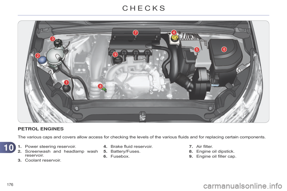
PETROL ENGINES
The various caps and covers allow access for checking the levels of the various fluids and for replacing certain components.
1.
Power
steering reservoir.
2.
Screenwash
and
headlamp
wash
reservoir
.
3.
Coolant
reservoir. 4.
Brake
fluid reservoir.
5.
Battery/Fuses.
6.
Fusebox.7.
Air
filter.
8.
Engine
oil dipstick.
9.
Engine
oil filler cap.
CHECKS
Page 179 of 340
1010
177
C4-2_en_Chap10_verification_ed01-2014
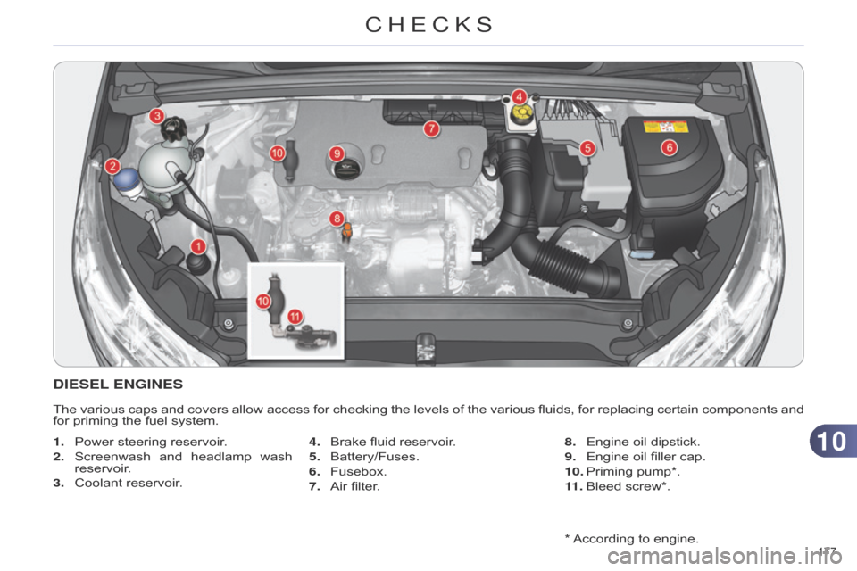
* According to engine.
DIESEL ENGINES
The various caps and covers allow access for checking the levels of the various fluids, for replacing certain components and for
priming the fuel system.
1.
Power
steering reservoir.
2.
Screenwash
and
headlamp
wash
reservoir
.
3.
Coolant
reservoir. 4.
Brake
fluid reservoir.
5.
Battery/Fuses.
6.
Fusebox.
7.
Air
filter.8.
Engine
oil dipstick.
9.
Engine
oil filler cap.
10.
Priming
pump*.
11 .
Bleed
screw*.
CHECKS
Page 181 of 340
1010
179
C4-2_en_Chap10_verification_ed01-2014
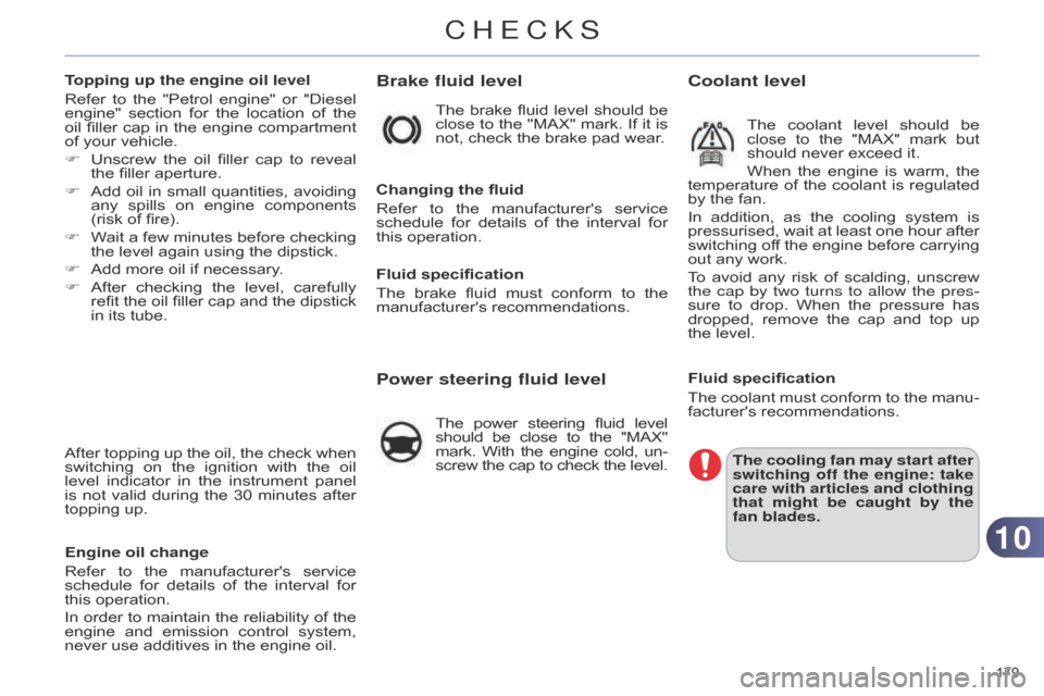
Brake fluid level
Changing the fluid
Refer
to
the
manufacturer's
service
schedule
for
details
of
the
interval
for
this
operation.
Fluid specification
The
brake
fluid
must
conform
to
the
manufacturer's
recommendations.
Power steering fluid level
The power steering fluid level should
be close to the "MAX" mark.
With
the
engine
cold,
un
-
screw
the
cap
to
check
the
level.
Coolant level
The coolant level should be close
to the "MAX" mark but
should
never exceed it.
When
the
engine
is
warm,
the
temperature
of
the
coolant
is
regulated
by
the
fan.
In
addition,
as
the
cooling
system
is
pressurised,
wait
at
least
one
hour
after
switching
of
f
the
engine
before
carrying
out
any
work.
To
avoid
any
risk
of
scalding,
unscrew
the cap by two turns to allow the pres
-
sure
to
drop.
When
the
pressure
has
dropped,
remove
the
cap
and
top
up
the
level.
Fluid specification
The
coolant
must
conform
to
the
manu
-
facturer's
recommendations.
The cooling fan may start after
switching off the engine: take
care with articles and clothing
that might be caught by the
fan blades.
The
brake
fluid
level
should
be
close
to
the
"MAX"
mark.
If
it
is
not,
check
the
brake
pad
wear.
Topping up the engine oil level
Refer
to
the
"Petrol
engine"
or
"Diesel
engine"
section
for
the
location
of
the
oil
filler
cap
in
the
engine
compartment
of
your
vehicle.
F
Unscrew
the
oil
filler
cap
to
reveal
the
filler
aperture.
F
Add
oil
in
small
quantities,
avoiding
any
spills
on
engine
components
(risk
of
fire).
F
W
ait
a
few
minutes
before
checking
the
level
again
using
the
dipstick.
F
Add
more
oil
if
necessary.
F
After
checking
the
level,
carefully
refit
the
oil
filler
cap
and
the
dipstick
in
its
tube.
After
topping
up
the
oil,
the
check
when
switching
on
the
ignition
with
the
oil
level
indicator
in
the
instrument
panel
is
not
valid
during
the
30
minutes
after
topping
up.
Engine oil change
Refer
to
the
manufacturer's
service
schedule
for
details
of
the
interval
for
this
operation.
In
order
to
maintain
the
reliability
of
the
engine
and
emission
control
system,
never
use
additives
in
the
engine
oil.
CHECKS
Page 192 of 340
1111
190
C4-2_en_Chap11_info-pratique_ed01-2014
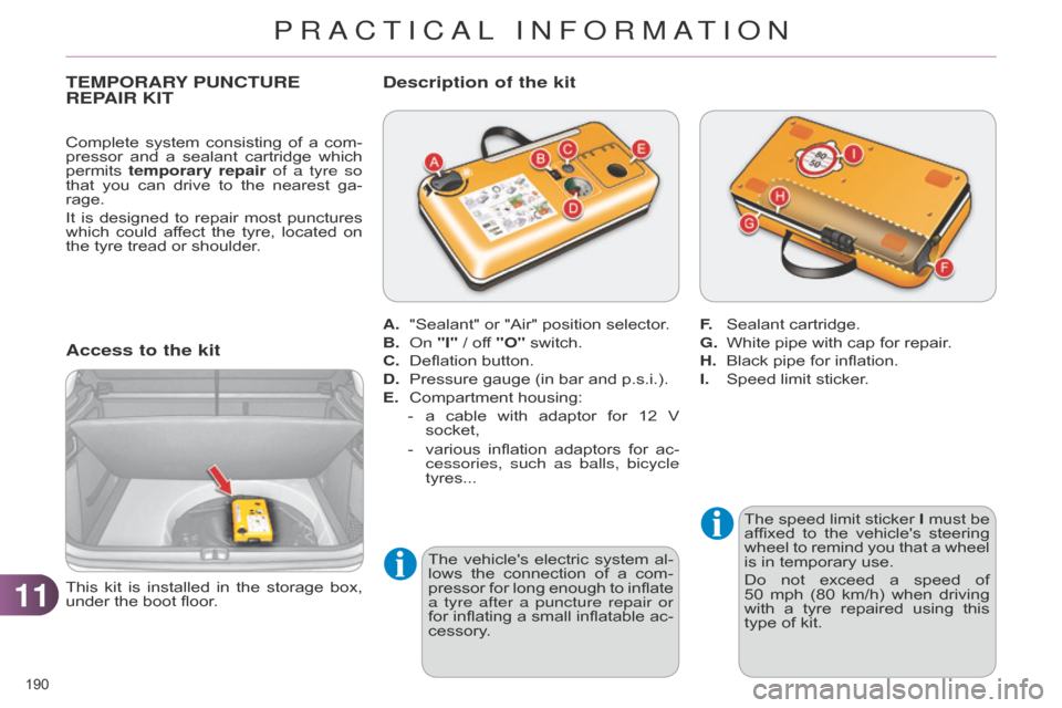
TEMPORARY PUNCTURE REP
AIR KIT
Access to the kit
The speed limit sticker I must be affixed
to the vehicle's steering
wheel
to
remind
you
that
a
wheel
is
in temporary use.
Do
not
exceed
a
speed
of
50
mph
(80
km/h)
when
driving
with
a
tyre
repaired
using
this
type
of kit.
This
kit
is
installed
in
the
storage
box,
under
the
boot
floor. A.
"Sealant"
or
"Air"
position
selector.
B.
o
n
"I"
/
off
"O"
switch.
C.
Deflation
button.
D.
Pressure
gauge
(in
bar
and
p.s.i.).
E.
Compartment
housing:
-
a
cable
with
adaptor
for
12
V
socket,
-
various
inflation
adaptors
for
ac
-
cessories, such as balls, bicycle
tyres...
Description of the kit
F. Sealant cartridge.
G.
White
pipe with cap for repair.
H.
Black
pipe for inflation.
I.
Speed
limit sticker.
Complete
system
consisting
of
a
com
-
pressor
and
a
sealant
cartridge
which
permits
temporary repair
of a tyre so
that
you
can
drive
to
the
nearest
ga
-
rage.
It
is
designed
to
repair
most
punctures
which
could
af
fect
the
tyre,
located
on
the
tyre
tread
or
shoulder.
The
vehicle's
electric
system
al
-
lows
the
connection
of
a
com
-
pressor
for
long
enough
to
inflate
a tyre after a puncture repair or
for
inflating
a
small
inflatable
ac
-
cessory.
PRACTICAL INFORMATION
Page 219 of 340
1111
217
C4-2_en_Chap11_info-pratique_ed01-2014
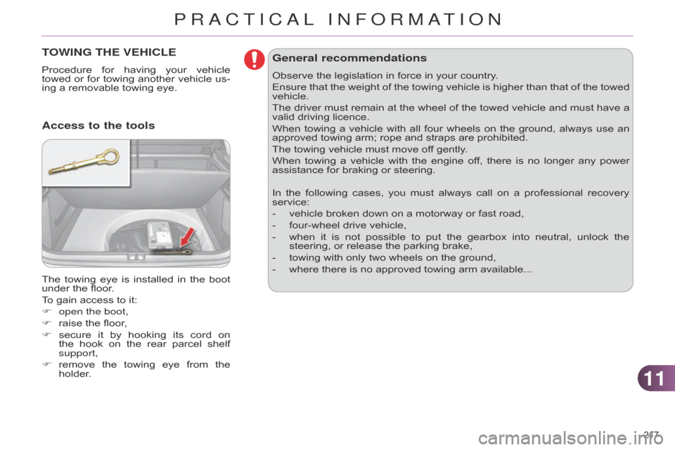
TOWING THE VEHICLE
Procedure for having your vehicle towed
or for towing another vehicle us -
ing
a removable towing eye.
The
towing
eye
is
installed
in
the
boot
under
the floor.
To
gain access to it:
F
open the boot,
F
raise
the floor,
F
secure
it
by
hooking
its
cord
on
the
hook
on
the
rear
parcel
shelf
support,
F
remove
the
towing
eye
from
the
holder
.
Access to the tools General recommendations
Observe the legislation in force in your country.
Ensure
that
the
weight
of
the
towing
vehicle
is
higher
than
that
of
the
towed
vehicle.
The
driver
must
remain
at
the
wheel
of
the
towed
vehicle
and
must
have
a
valid
driving licence.
When
towing
a
vehicle
with
all
four
wheels
on
the
ground,
always
use
an
approved
towing arm; rope and straps are prohibited.
The
towing vehicle must move off gently.
When
towing
a
vehicle
with
the
engine
of
f,
there
is
no
longer
any
power
assistance
for braking or steering.
In
the
following
cases,
you
must
always
call
on
a
professional
recovery
service:
-
vehicle
broken down on a motorway or fast road,
-
four-wheel
drive vehicle,
-
when
it
is
not
possible
to
put
the
gearbox
into
neutral,
unlock
the
steering,
or release the parking brake,
-
towing
with only two wheels on the ground,
-
where
there is no approved towing arm available...
PRACTICAL INFORMATION
Page 220 of 340
1111
218
C4-2_en_Chap11_info-pratique_ed01-2014
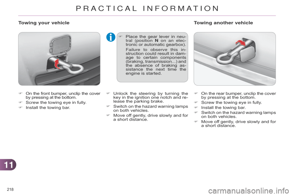
F On the front bumper , unclip the cover by
pressing at the bottom.
F
Screw
the towing eye in fully.
F
Install
the towing bar.
Towing your vehicle
F Place the gear lever in neu -
tral (position N on an elec-
tronic
or automatic gearbox).
Failure to observe this in
-
struction
could
result
in
dam
-
age
to
certain
components
(braking,
transmission...)
and
the
absence
of
braking
as
-
sistance
the
next
time
the
engine
is started. F
On
the
rear
bumper
,
unclip
the
cover by
pressing at the bottom.
F
Screw
the towing eye in fully.
F
Install
the towing bar.
F
Switch
on
the
hazard
warning
lamps
on
both vehicles.
F
Move
of
f
gently
,
drive
slowly
and
for
a
short distance.
Towing another vehicle
F Unlock the steering by turning the key
in the ignition one notch and re -
lease
the parking brake.
F
Switch
on
the
hazard
warning
lamps
on
both vehicles.
F
Move
of
f
gently
,
drive
slowly
and
for
a
short distance.
PRACTICAL INFORMATION
Page 224 of 340
1111
222
C4-2_en_Chap11_info-pratique_ed01-2014
Installation of radio
communication transmitters
Before
installin
g
any
after-
market
radio
communication
transmitter
,
you
can
contact
a
CITROËN
dealer
for
the
speci
-
fication
of
transmitters
which
can
be
fitted
(frequency
,
maxi
-
mum
power
,
aerial
position,
specific
installation
require
-
ments),
in
line
with
the
V
ehicle
Electromagnetic
Compatibility
Directive (2004/104/EC). Depending
on the legislation in force
in the country, certain safe-
ty
equipment
may
be
compul
-
sory:
high
visibility
safety
vests,
warning
triangles,
breathalyzers,
spare
bulbs,
spare
fuses,
fire
ex
-
tinguisher,
first
aid
kit,
mud
flaps
at
the rear of the vehicle.
The
fitting
of
electrical
equip
-
ment
or
accessories
which
are
not
recommended
by
CITROËN
may
result
in
a
failure
of
your
ve
-
hicle's
electronic
system
and
ex
-
cessive
electrical consumption.
Contact
a
CITROËN
dealer
for
information
on
the
range
of
recommended
equipment
and
accessories.
"Multimedia":
audio
systems,
steering
mounted
au
-
dio
controls,
speakers,
Hi-Fi
module,
Bluetooth
hands-free
system,
port
-
able
satellite
navigation
system,
semi-
integral
support
bracket
for
portable
navigation
system,
mapping
update
CD,
driving
assistant,
portable
video
screen,
portable
video
support
bracket,
230
V/50
Hz
socket,
230
V/50
Hz
adap
-
tor, iPhone
® compatible mobile phone charger
,
mobile phone/smartphone
bracket,
Wi-Fi on board... By
going
to
a
CITROËN
dealer,
you
can
also
obtain
cleaning
and
maintenance
products
(interior
and
exterior)
- in-
cluding
ecological
products
in
the
"TECHNA
TURE"
range
-,
products
for
topping
up
(screenwash...),
touch-up
pens
and
paint
aerosols
for
the
exact
colour
of
your
vehicle,
recharges
(car
-
tridge
for
the
temporary
puncture
repair
kit...),
...
PRACTICAL INFORMATION