Citroen C4 PICASSO RHD 2015 1.G Owner's Manual
Manufacturer: CITROEN, Model Year: 2015, Model line: C4 PICASSO RHD, Model: Citroen C4 PICASSO RHD 2015 1.GPages: 428, PDF Size: 10.09 MB
Page 261 of 428
259
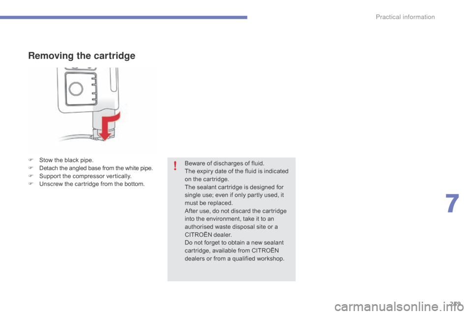
Removing the cartridge
F Stow the black pipe.
F D etach the angled base from the white pipe.
F
S
upport the compressor vertically.
F
U
nscrew the cartridge from the bottom.Beware
of discharges of fluid.
The
expiry date of the fluid is indicated
o
n the cartridge.
The
sealant cartridge is designed for
s
ingle use; even if only partly used, it
m
ust be replaced.
After
use, do not discard the cartridge
i
nto the environment, take it to an
a
uthorised waste disposal site or a
C
ITROËN dealer.
Do
not forget to obtain a new sealant
c
artridge, available from CITROËN
d
ealers or from a qualified workshop.
7
Practical information
Page 262 of 428

260
Checking tyre pressures /
inflating accessories
You can also use the compressor, without injecting any product, to:
-
c
heck or adjust the pressure of your tyres,
-
i
nflate other accessories (balls,
b
icycle tyres...).
F
T
urn the selector A to the "
ai
r"
position.
F
U
ncoil the black pipe H
f
ully.
F
C
onnect the black pipe to the
v
alve of the wheel or accessory.
I
f necessary, fit one of the adaptors
s
upplied with the kit first. F
C onnect the compressor's electrical
c
onnector to the vehicle's 12 V socket.
F
S
tart the vehicle and let the engine run.
F
A
djust the pressure using the compressor
(
to inflate: switch B in position "I";
t
o deflate: switch B in position "O"
and
p
ress button C),
according to the vehicle's
t
yre pressure label or the accessory's
p
ressure label.
F
R
emove the kit then stow it.Should
the pressure of one or more
t
yres be adjusted, it is necessary to
r
einitialise the under-inflation detection
s
ystem.
Refer
to the "Under-inflation detection"
s
ection.
Practical information
Page 263 of 428
261
Changing a wheel
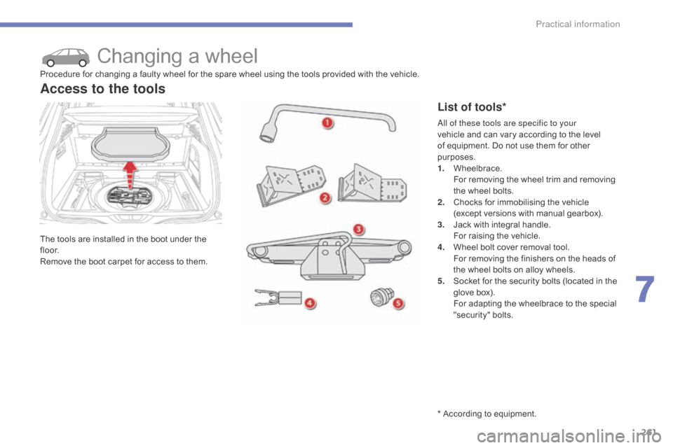
The tools are installed in the boot under the fl o o r.
Remove
the boot carpet for access to them.
Access to the tools
List of tools*
Procedure for changing a faulty wheel for the spare wheel using the tools provided with the vehicle.
* According to equipment.
al
l of these tools are specific to your
vehicle
and can vary according to the level
o
f equipment. Do not use them for other
p
urposes.
1.
W
heelbrace.
F
or removing the wheel trim and removing
t
he wheel bolts.
2.
C
hocks for immobilising the vehicle
(except
versions with manual gearbox).
3.
J
ack with integral handle.
F
or raising the vehicle.
4.
W
heel bolt cover removal tool.
F
or removing the finishers on the heads of
t
he wheel bolts on alloy wheels.
5.
S
ocket for the security bolts (located in the
g
love box).
F
or adapting the wheelbrace to the special
"s
ecurity"
b
olts.
7
Practical information
Page 264 of 428
262
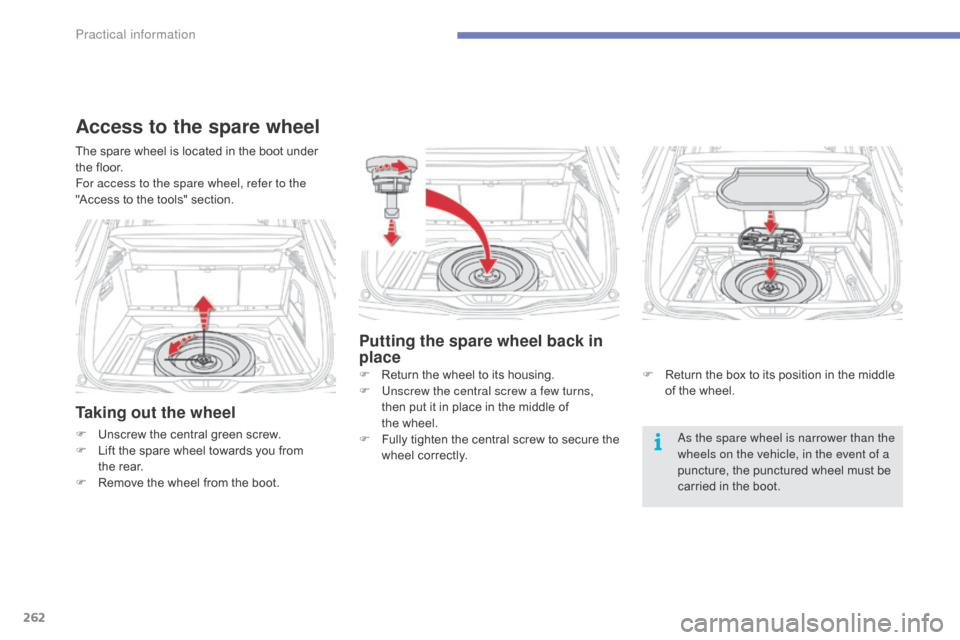
Taking out the wheel
F Unscrew the central green screw.
F L ift the spare wheel towards you from
t
he rear.
F
R
emove the wheel from the boot.as t he spare wheel is narrower than the
wheels on the vehicle, in the event of a
puncture,
the punctured wheel must be
c
arried in the boot.
The
spare wheel is located in the boot under
t
he floor.
Fo
r access to the spare wheel, refer to the
"Access to the tools" section.
Access to the spare wheel
Putting the spare wheel back in
place
F Return
the wheel to its housing.
F U nscrew the central screw a few turns,
then
put it in place in the middle of
t
he wheel.
F
F
ully
t
ighten
t
he
c
entral
s
crew
t
o
s
ecure
t
he
w
heel correctly. F
R eturn the box to its position in the middle o
f the wheel.
Practical information
Page 265 of 428
263
* Depending on version. The complete tooling i
s with the spare wheel.
Changing a wheelProcedure for changing a wheel with a punctured tyre by the spare wheel using the tools provided with the vehicle.
S
ome
of
the
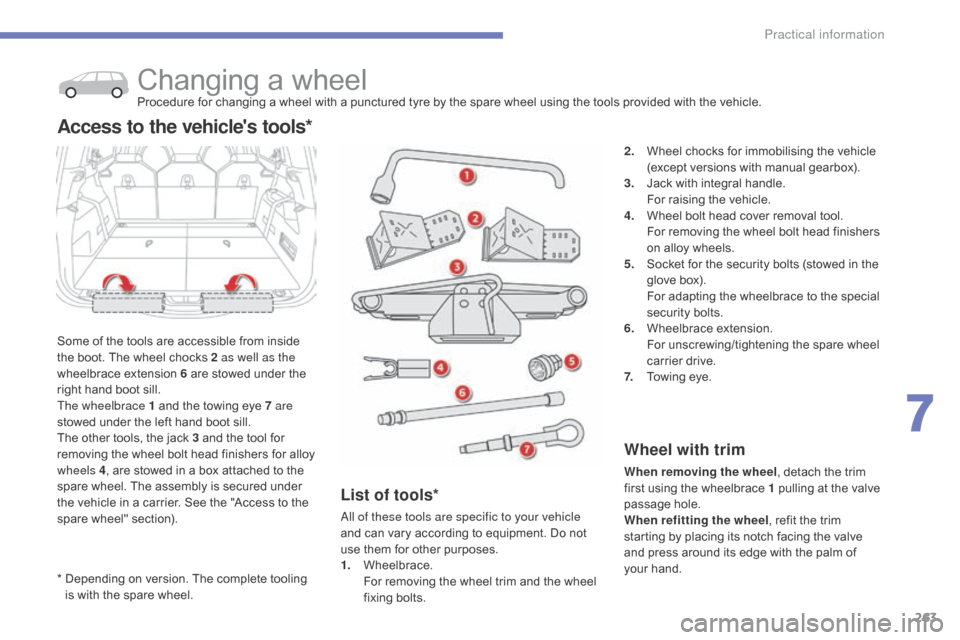
tools are accessible from inside
t
he
boot.
The
wheel chocks 2 as well as the
wheelbrace
extension 6 are stowed under the
r
ight
hand
boot sill.
The wheelbrace 1
and the towing eye 7 are
stowed
under
the left hand boot sill.
The
other
tools, the jack 3 and the tool for
r
emoving
the
wheel bolt head finishers for alloy
w
heels 4 ,
are
stowed in a box attached to the
s
pare
wheel.
The assembly is secured under
t
he
vehicle
in
a carrier. See the "Access to the
s
pare
wheel"
section).
Access to the vehicle's tools*
2. Wheel chocks for immobilising the vehicle (
except versions with manual gearbox).
3.
J
ack with integral handle.
F
or raising the vehicle.
4.
W
heel bolt head cover removal tool.
F
or removing the wheel bolt head finishers
o
n alloy wheels.
5.
S
ocket for the security bolts (stowed in the
g
love box).
F
or adapting the wheelbrace to the special
s
ecurity bolts.
6.
W
heelbrace
e
xtension.
F
or unscrewing/tightening the spare wheel
c
arrier drive.
7.
T
owing eye.
Wheel with trim
When removing the wheel , detach the trim f
irst using the wheelbrace 1 pulling at the valve
p
assage hole.
When refitting the wheel ,
refit the trim
s
tarting by placing its notch facing the valve
a
nd press around its edge with the palm of
y
our hand.
List of tools*
all of these tools are specific to your vehicle
and can vary according to equipment. Do not
u
se them for other purposes.
1.
W
heelbrace.
F
or removing the wheel trim and the wheel
f
ixing
bol
ts.
7
Practical information
Page 266 of 428
264
* Depending on version.
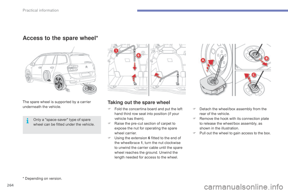
Taking out the spare wheelThe spare wheel is supported by a carrier underneath t he v ehicle.
Access to the spare wheel*
F Detach the wheel/box assembly from the r
ear of the vehicle.
F
R
emove the hook with its connection plate
t
o release the wheel/box assembly, as
s
hown in the illustration.
F
Pull out the wheel to gain access to the box.
F Fold the concertina board and put the left h
and third row seat into position (if your
v
ehicle has them).
F
R
aise the pre-cut section of carpet to
e
xpose the nut for operating the spare
w
heel carrier.
F
U
sing the extension 6 fitted to the end of
t
he wheelbrace 1 ,
turn the nut clockwise
t
o unwind the carrier cable until the spare
w
heel reaches the ground. Unwind the
l
ength needed for access to the wheel.
Only
a
"space-saver"
type
of
spare
w
heel
can
be
fitted
under
the
vehicle.
Practical information
Page 267 of 428
265
A puncture wheel from the vehicle cannot be fitted under the vehicle. It
m
ust
b
e
c
arried
i
n
t
he
b
oot.
U
se
a
c
over
t
o protect the boot.
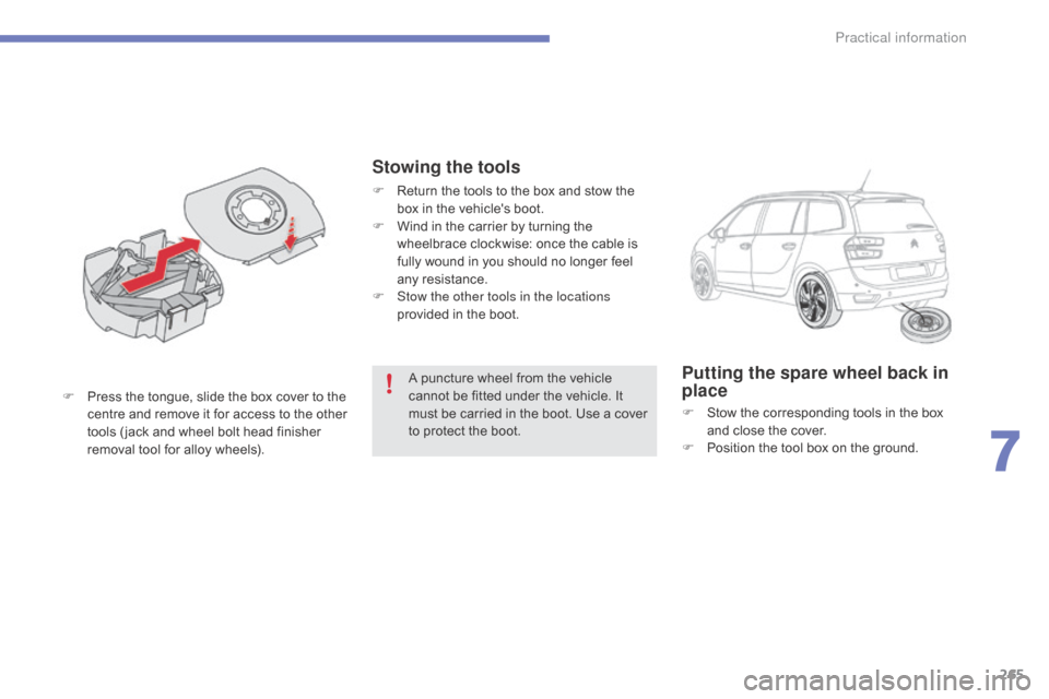
F
P
ress
the
tongue,
slide
the
box
cover
to
the
c
entre
a
nd
r
emove
i
t
f
or
a
ccess
t
o
t
he
o
ther
t
ools
( jack
and
wheel
bolt
head
finisher
r
emoval
tool
for
alloy
wheels).Putting the spare wheel back in
place
F Stow the corresponding tools in the box a
nd close the cover.
F
P
osition the tool box on the ground.
Stowing the tools
F Return the tools to the box and stow the b
ox in the vehicle's boot.
F
W
ind in the carrier by turning the
w
heelbrace clockwise: once the cable is
f
ully wound in you should no longer feel
an
y
r
esistance.
F
S
tow the other tools in the locations
provided
in the boot.
7
Practical information
Page 268 of 428
266
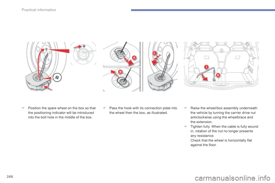
F Pass the hook with its connection plate into t
he wheel then the box, as illustrated.F
Ra ise t he w heel/box a ssembly u nderneath t
he vehicle by turning the carrier drive nut
a
nticlockwise using the wheelbrace and
t
he extension.
F
T
ighten fully. When the cable is fully wound
i
n, rotation of the nut no longer presents
an
y
r
esistance.
C
heck that the wheel is horizontally flat
a
gainst the floor.
F
P
osition
the
spare
wheel
on
the
box
so
that
t
he
positioning
indicator
will
be
introduced
i
nto
the
bolt
hole
in
the
middle
of
the
box.
Pr
Page 269 of 428
267
Removing a wheel
Parking the vehicle
Immobilise the vehicle where it does not block traffic: the ground must be level,
s
table and not slippery.
Apply
the parking brake unless it has
b
een programmed to automatic mode,
s
witch off the ignition and engage first
g
ear* to block the wheels.
Check
that the braking warning lamp
a
nd the P warning lamp in the parking
b
rake control lever come on.
For
greater safety, place a chock 2
against
the wheel opposite to the one
b
eing
c
hanged.
The
occupants must get out of the
v
ehicle and wait where they are safe.
Never
go underneath a vehicle raised
u
sing a jack; use an axle stand.
List of operations
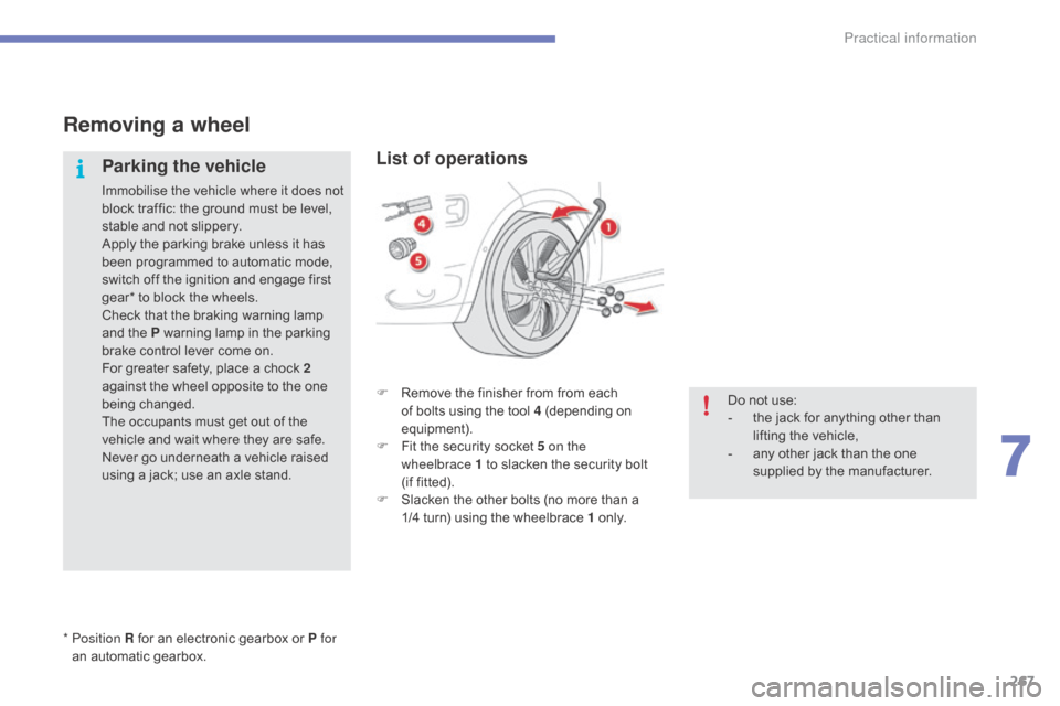
F Remove the finisher from from each o
f bolts using the tool 4 (depending on
e
quipment).
F
F
it the security socket 5 on the
wheelbrace
1 to slacken the security bolt
(if
fitted).
F
S
lacken the other bolts (no more than a
1
/4 turn) using the wheelbrace 1
o
n l y.
*
Position R
for
an
electronic
gearbox
or
P for
an
automatic
gearbox. Do
not use:
-
t
he jack for anything other than
l
ifting the vehicle,
-
a
ny other jack than the one
s
upplied by the manufacturer.
7
Practical information
Page 270 of 428
268
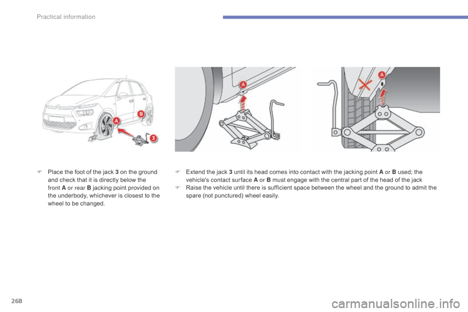
F Place the foot of the jack 3 on the ground a
nd check that it is directly below the
f
ront A or rear B jacking point provided on
t
he underbody, whichever is closest to the
w
heel to be changed. F
E xtend the jack 3 until its head comes into contact with the jacking point A or B used; the v
ehicle's contact sur face A or B must engage with the central part of the head of the jack
F
R
aise the vehicle until there is sufficient space between the wheel and the ground to admit the
s
pare (not punctured) wheel easily.
Practical information