Citroen C4 RHD 2013.5 2.G Owner's Manual
Manufacturer: CITROEN, Model Year: 2013.5, Model line: C4 RHD, Model: Citroen C4 RHD 2013.5 2.GPages: 328, PDF Size: 28.6 MB
Page 201 of 328
11
PRACTICAL INFORMATION
199
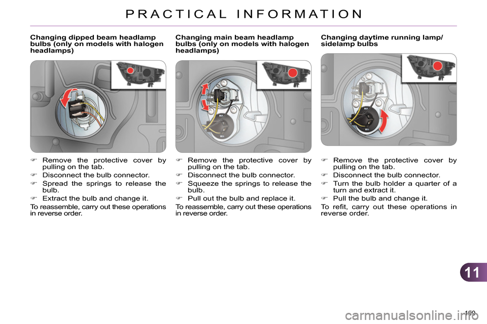
Changing dipped beam headlamp
bulbs (only on models with halogen
headlamps)
Changing daytime running lamp/
sidelamp bulbs
Remove the protective cover by
pulling on the tab.
Disconnect the bulb connector.
Turn the bulb holder a quarter of a
turn and extract it.
Pull the bulb and change it.
To r efi t, carry out these operations in
reverse order.
Remove the protective cover by
pulling on the tab.
Disconnect the bulb connector.
Spread the springs to release the
bulb.
Extract the bulb and change it.
To reassemble, carry out these operations
in reverse order.
Changing main beam headlamp
bulbs (only on models with halogen
headlamps)
Remove the protective cover by
pulling on the tab.
Disconnect the bulb connector.
Squeeze the springs to release the
bulb.
Pull out the bulb and replace it.
To reassemble, carry out these operations
in reverse order.
Page 202 of 328
11
PRACTICAL INFORMATION
200
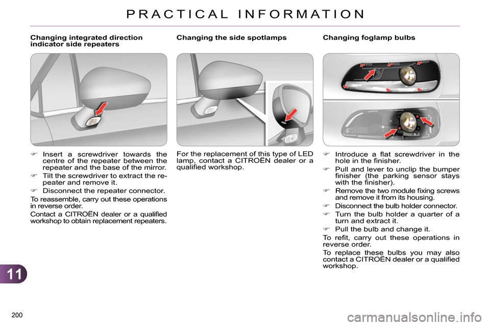
Introduce a fl at screwdriver in the
hole in the fi nisher.
Pull and lever to unclip the bumper
fi nisher (the parking sensor stays
with the fi nisher).
Remove the two module fi xing screws
and remove it from its housing.
Disconnect the bulb holder connector.
Turn the bulb holder a quarter of a
turn and extract it.
Pull the bulb and change it.
To r efi t, carry out these operations in
reverse order.
To replace these bulbs you may also
contact a CITROËN dealer or a qualifi ed
workshop.
Changing foglamp bulbs
Changing the side spotlamps
For the replacement of this type of LED
lamp, contact a CITROËN dealer or a
qualifi ed workshop.
Changing integrated direction
indicator side repeaters
Insert a screwdriver towards the
centre of the repeater between the
repeater and the base of the mirror.
Tilt the screwdriver to extract the re-
peater and remove it.
Disconnect the repeater connector.
To reassemble, carry out these operations
in reverse order.
Contact a CITROËN dealer or a qualifi ed
workshop to obtain replacement repeaters.
Page 203 of 328
11
PRACTICAL INFORMATION
201
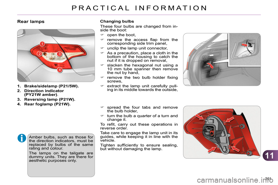
Rear lamps
1.
Brake/
sidelamp
(P21/5W).
2.
Direction
indicator
(PY21W amber)
.
3.
Reversing lamp (P21W).
4.
Rear
foglamp
(P21W).
Amber bulbs, such as those for
the direction indicators, must be
replaced by bulbs of the same
rating and colour.
The lamps on the tailgate are
dummy units. They are there for
aesthetic purposes only.
Changing bulbs
These four bulbs are changed from in-
side the boot:
open the boot,
remove the access fl ap from the
corresponding side trim panel,
unclip the lamp unit connector,
As a precaution, place a cloth in the
bottom of the housing to catch the
nut if it is dropped on removal,
slacken the hexagonal nut using a
10 mm tube spanner then remove
the nut by hand,
remove the two bulb holder fi xing
screws,
extract the lamp unit carefully pull-
ing in its middle towards the outside,
spread the four tabs and remove
the bulb holder,
turn the bulb a quarter of a turn and
change it.
To r efi t, carry out these operations in
reverse order.
Take care to engage the lamp unit in its
guides, while keeping it in line with the
vehicle.
Tighten suffi ciently to ensure sealing,
but without damaging the lamp.
Page 204 of 328
11
PRACTICAL INFORMATION
202
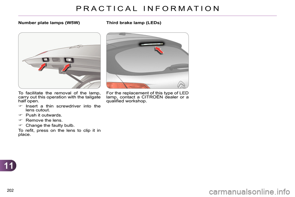
To facilitate the removal of the lamp,
carry out this operation with the tailgate
half open.
Insert a thin screwdriver into the
lens cutout.
Push it outwards.
Remove the lens.
Change the faulty bulb.
To r efi t, press on the lens to clip it in
place.
Number plate lamps (W5W)
For the replacement of this type of LED
lamp, contact a CITROËN dealer or a
qualifi ed workshop.
Third brake lamp (LEDs)
Page 205 of 328
11
PRACTICAL INFORMATION
203
CHANGING A FUSE
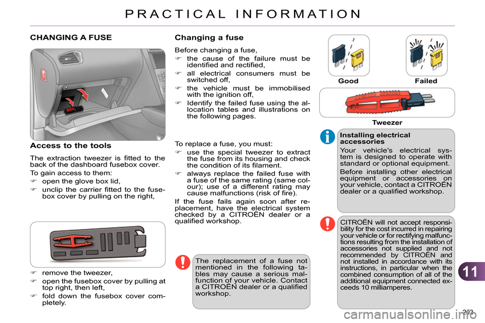
Access to the tools
The extraction tweezer is fi tted to the
back of the dashboard fusebox cover.
To gain access to them:
open the glove box lid,
unclip the carrier fi tted to the fuse-
box cover by pulling on the right,
Changing a fuse
Before changing a fuse,
the cause of the failure must be
identifi ed and rectifi ed,
all electrical consumers must be
switched off,
the vehicle must be immobilised
with the ignition off,
Identify the failed fuse using the al-
location tables and illustrations on
the following pages.
Good
Failed
To replace a fuse, you must:
use the special tweezer to extract
the fuse from its housing and check
the condition of its fi lament.
always replace the failed fuse with
a fuse of the same rating (same col-
our); use of a different rating may
cause malfunctions (risk of fi re).
If the fuse fails again soon after re-
placement, have the electrical system
checked by a CITROËN dealer or a
qualifi ed workshop.
Installing electrical
accessories
Your vehicle's electrical sys-
tem is designed to operate with
standard or optional equipment.
Before installing other electrical
equipment or accessories on
your vehicle, contact a CITROËN
dealer or a qualifi ed workshop.
CITROËN will not accept responsi-
bility for the cost incurred in repairing
your vehicle or for rectifying malfunc-
tions resulting from the installation of
accessories not supplied and not
recommended by CITROËN and
not installed in accordance with its
instructions, in particular when the
combined consumption of all of the
additional equipment connected ex-
ceeds 10 milliamperes.
The replacement of a fuse not
mentioned in the following ta-
bles may cause a serious mal-
function of your vehicle. Contact
a CITROËN dealer or a qualifi ed
workshop.
Tweezer
remove the tweezer,
open the fusebox cover by pulling at
top right, then left,
fold down the fusebox cover com-
pletely.
Page 206 of 328
11
PRACTICAL INFORMATION
204
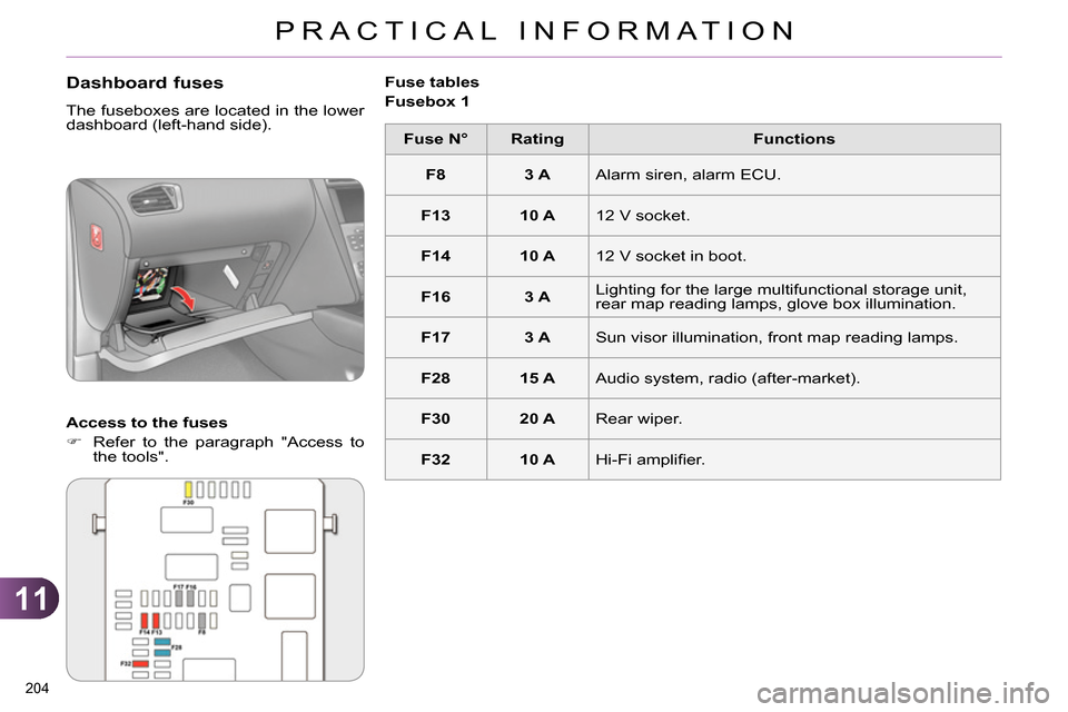
Dashboard fuses
The fuseboxes are located in the lower
dashboard (left-hand side).
Access to the fuses
Refer to the paragraph "Access to
the tools".
Fuse tables
Fusebox 1
Fuse N°
Rating
Functions
F8
3 A
Alarm siren, alarm ECU.
F13
10 A
12 V socket.
F14
10 A
12 V socket in boot.
F16
3 A
Lighting for the large multifunctional storage unit,
rear map reading lamps, glove box illumination.
F17
3 A
Sun visor illumination, front map reading lamps.
F28
15 A
Audio system, radio (after-market).
F30
20 A
Rear wiper.
F32
10 A
Hi-Fi amplifi er.
Page 207 of 328
11
PRACTICAL INFORMATION
205
Fuse N°
Rating
Functions
F36
15 A
Rear 12 V socket.
F37
-
Not used.
F38
-
Not used.
F39
-
Not used.
F40
-
Not used.
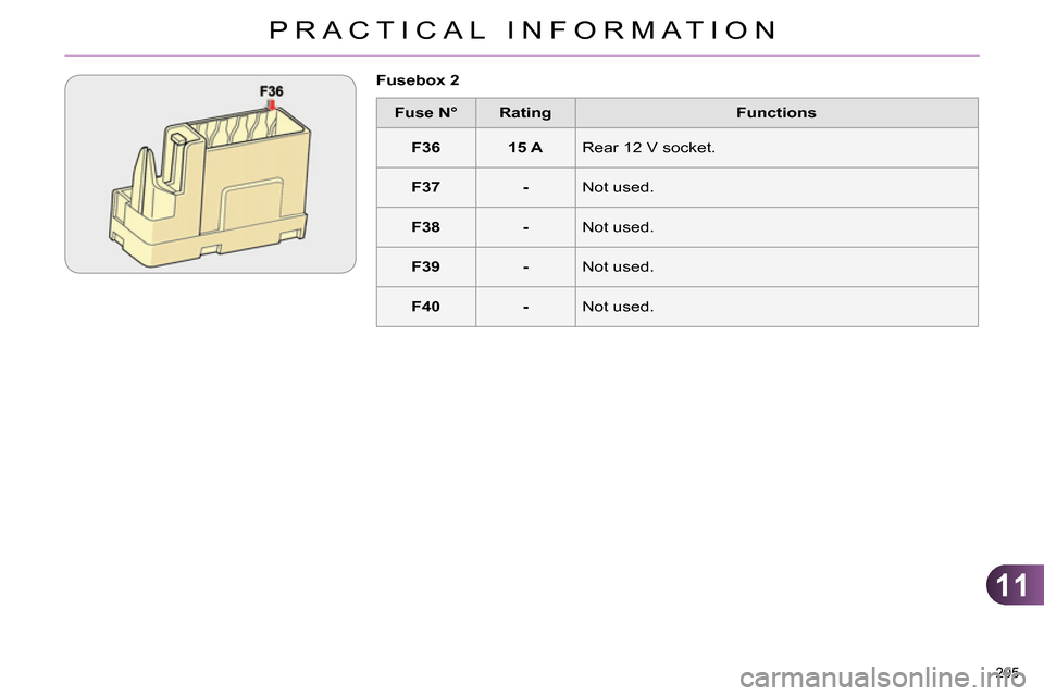
Fusebox 2
Page 208 of 328
11
PRACTICAL INFORMATION
206
Fuse N°
Rating
Functions
F19
30 A
Windscreen wipers slow / fast speed.
F20
15 A
Front and rear screenwash pump.
F21
20 A
Headlamp wash pump.
F22
15 A
Horn.
F23
15 A
Right-hand main beam headlamp.
F24
15 A
Left-hand main beam headlamp.
F27
5 A
Left-hand dipped headlamp.
F28
5 A
Right-hand dipped headlamp.
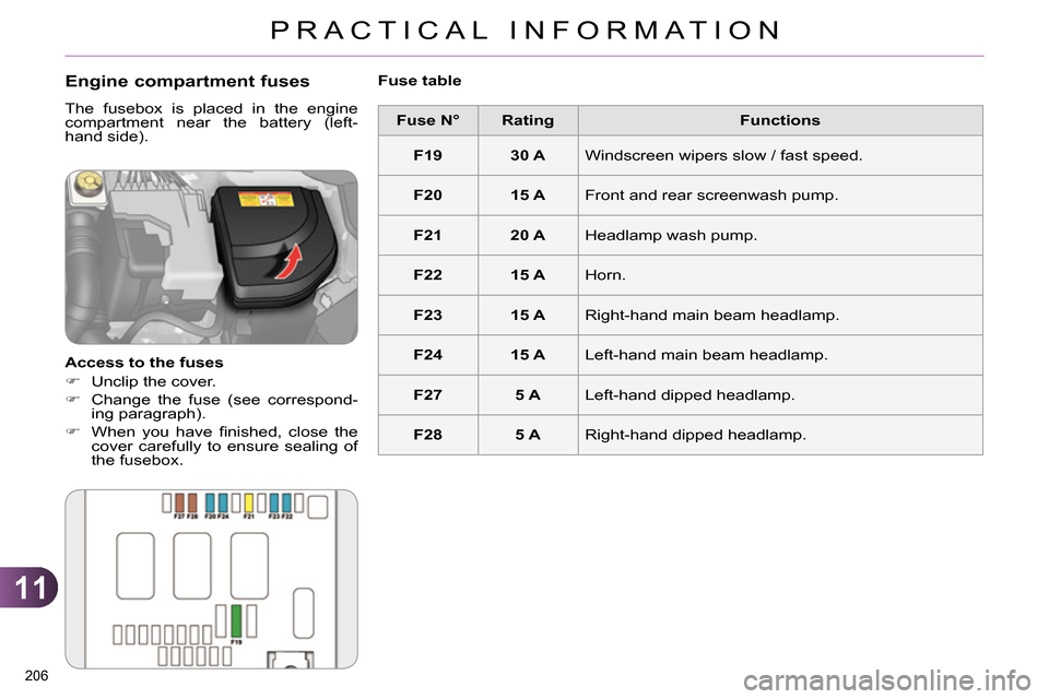
Engine compartment fuses
The fusebox is placed in the engine
compartment near the battery (left-
hand side).
Access to the fuses
Unclip the cover.
Change the fuse (see correspond-
ing paragraph).
When you have fi nished, close the
cover carefully to ensure sealing of
the fusebox.
Fuse table
Page 209 of 328
11
PRACTICAL INFORMATION
207
When your vehicle's battery is dis-
charged, the engine can be started using
a slave battery (external or on another
vehicle) and jump lead cables.
Starting using another battery
12 V BATTERY
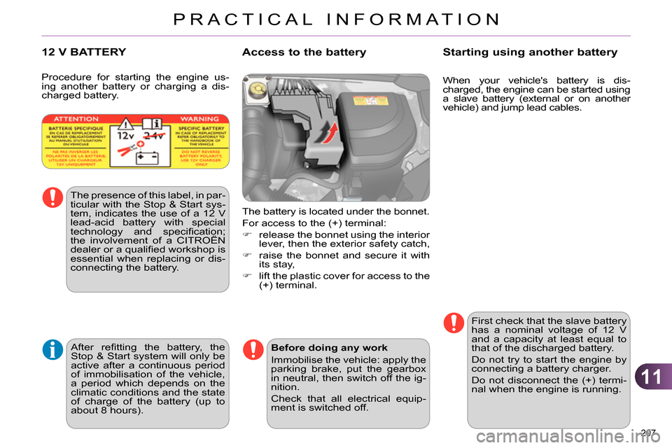
The battery is located under the bonnet.
For access to the (+) terminal:
release the bonnet using the interior
lever, then the exterior safety catch,
raise the bonnet and secure it with
its stay,
lift the plastic cover for access to the
(+) terminal.
Access to the battery
The presence of this label, in par-
ticular with the Stop & Start sys-
tem, indicates the use of a 12 V
lead-acid battery with special
technology and specifi cation;
the involvement of a CITROËN
dealer or a qualifi ed workshop is
essential when replacing or dis-
connecting the battery.
Procedure for starting the engine us-
ing another battery or charging a dis-
charged battery.
After refi tting the battery, the
Stop & Start system will only be
active after a continuous period
of immobilisation of the vehicle,
a period which depends on the
climatic conditions and the state
of charge of the battery (up to
about 8 hours).
First check that the slave battery
has a nominal voltage of 12 V
and a capacity at least equal to
that of the discharged battery.
Do not try to start the engine by
connecting a battery charger.
Do not disconnect the (+) termi-
nal when the engine is running.
Before doing any work
Immobilise the vehicle: apply the
parking brake, put the gearbox
in neutral, then switch off the ig-
nition.
Check that all electrical equip-
ment is switched off.
Page 210 of 328
11
PRACTICAL INFORMATION
208
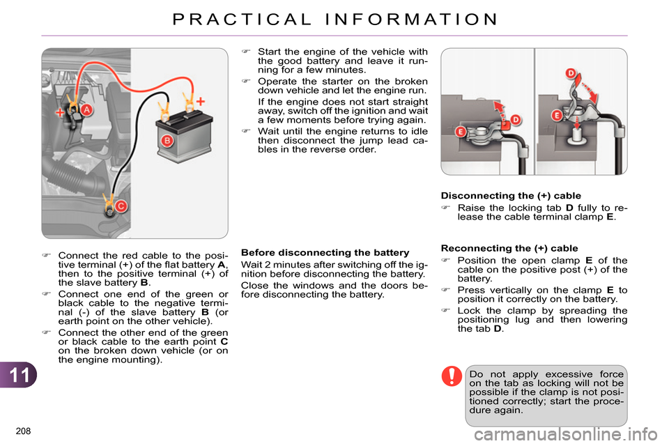
Reconnecting the (+) cable
Position the open clamp E
of the
cable on the positive post (+) of the
battery.
Press vertically on the clamp E
to
position it correctly on the battery.
Lock the clamp by spreading the
positioning lug and then lowering
the tab D
.
Start the engine of the vehicle with
the good battery and leave it run-
ning for a few minutes.
Operate the starter on the broken
down vehicle and let the engine run
.
If the engine does not start straight
away, switch off the ignition and wait
a few moments before trying again.
Wait until the engine returns to idle
then disconnect the jump lead ca-
bles in the reverse order.
Before disconnecting the battery
Wait 2 minutes after switching off the ig-
nition before disconnecting the battery.
Close the windows and the doors be-
fore disconnecting the battery.
Disconnecting the (+) cable
Raise the locking tab D
fully to re-
lease the cable terminal clamp E
.
Do not apply excessive force
on the tab as locking will not be
possible if the clamp is not posi-
tioned correctly; start the proce-
dure again.
Connect the red cable to the posi-
tive terminal (+) of the fl at battery A
,
then to the positive terminal (+) of
the slave battery B
.
Connect one end of the green or
black cable to the negative termi-
nal (-) of the slave battery B
(or
earth point on the other vehicle).
Connect the other end of the green
or black cable to the earth point C
on the broken down vehicle (or on
the engine mounting).