tow Citroen C5 2016 (RD/TD) / 2.G Owner's Guide
[x] Cancel search | Manufacturer: CITROEN, Model Year: 2016, Model line: C5, Model: Citroen C5 2016 (RD/TD) / 2.GPages: 366, PDF Size: 30.93 MB
Page 172 of 366

170
C5_en_Chap07_securite-enfant_ed01-2015
(a) Universal child seat: child seat which can
be installed in all vehicles using the seat
belt.
( b ) Group 0: from birth to 10 kg. Shells and
"car cots" cannot be installed on the front
passenger seat.
( c ) Consult the current legislation for your
country before driving with your child in this
seat.
(d) To install a child seat on a rear seat,
rear ward facing or for ward facing, move
the front seat for ward, then straighten the
backrest to allow enough space for the
child seat and the child's legs. Remove and stow the head restraint
before installing a child seat with a
backrest on a passenger seat. Refit the
head restraint once the child seat has
been removed.
(e)
When a rear ward facing child seat is
installed on the front passenger seat , the
passenger airbag must be deactivated.
o therwise the child would risk being
seriously injured or killed if the
airbag were deployed . When a for ward
facing child seat is installed on the front
passenger seat , the passenger airbag
must remain active.
(f ) A child seat with a support leg must never
be installed on the centre rear seat .
Child safety
Page 175 of 366

173
C5_en_Chap07_securite-enfant_ed01-2015
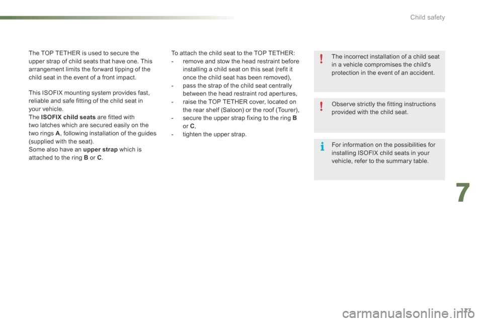
To attach the child seat to the TOP TETHER:
- remove and stow the head restraint before
installing a child seat on this seat (refit it
once the child seat has been removed),
- pass the strap of the child seat centrally
between the head restraint rod apertures,
- raise the T oP TETHER cover, located on
the rear shelf (Saloon) or the roof (Tourer),
- secure the upper strap fixing to the ring B
or C ,
- tighten the upper strap.
The T
oP TETHER is used to secure the
upper strap of child seats that have one. This
arrangement limits the for ward tipping of the
child seat in the event of a front impact. The incorrect installation of a child seat
in a vehicle compromises the child's
protection in the event of an accident.
Observe strictly the fitting instructions
provided with the child seat.
This ISOFIX mounting system provides fast,
reliable and safe fitting of the child seat in
your vehicle.
The ISOFIX child seats are fitted with
two latches which are secured easily on the
two rings A
, following installation of the guides
(supplied with the seat).
Some also have an upper strap which is
attached to the ring B or C . For information on the possibilities for
installing ISOFIX child seats in your
vehicle, refer to the summary table.
7
Child safety
Page 177 of 366

175
C5_en_Chap07_securite-enfant_ed01-2015
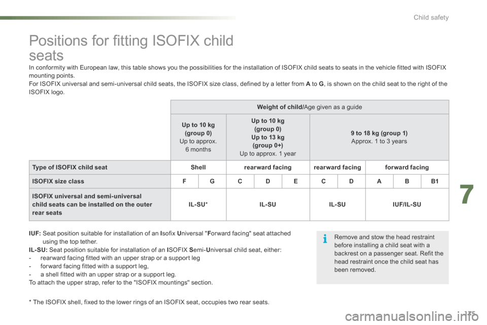
Positions for fitting ISOFIX child
seats
I UF: Seat position suitable for installation of an I sofix Universal " For ward facing" seat attached
using the top tether.
IL- SU: Seat position suitable for installation of an I So FIX S emi-Universal child seat, either:
- rear ward facing fitted with an upper strap or a support leg
- for ward facing fitted with a support leg,
- a shell fitted with an upper strap or a support leg.
To attach the upper strap, refer to the "ISOFIX mountings" section. Weight of child/
Age given as a guide
Up to 10 kg (group 0)
Up to approx. 6 months Up to 10 kg
(group 0)
Up to 13 kg (group 0+)
Up to approx. 1 year 9 to 18 kg (group 1)
Approx. 1 to 3 years
Type of ISOFIX child seat Shellrearward facing rearward facing forward facing
ISOFIX size class FG CD EC DABB1
ISOFIX universal and semi-universal
child seats can be installed on the outer
rear seats IL- SU
* IL- SU IL- SUIUF/IL- SU
* The ISOFIX shell, fixed to the lower rings of an ISOFIX seat, occupies two rear seats.
In conformity with European law, this table shows you the possibilities for the installation of ISOFIX child seats to seats in the vehicle fitted with ISOFIX
mounting points.
For ISOFIX universal and semi-universal child seats, the ISOFIX size class, defined by a letter from A to G
, is shown on the child seat to the right of the
ISOFIX logo.
Remove and stow the head restraint
before installing a child seat with a
backrest on a passenger seat. Refit the
head restraint once the child seat has
been removed.
7
Child safety
Page 187 of 366

185
C5_en_Chap08_information_ed01-2015
Changing a wheel
Access to the tools
For vehicles supplied with a standard spare
wheel (same size as the four wheels), the tools
are stowed in a carrier, located in the spare
wheel.
F Release the retaining strap for access to it.
List of tools
all of these tools are specific to your vehicle
and may vary according to equipment. Do not
use them for any other purpose. 1.
Wheelbrace.
Used for removing the wheel trim and the
wheel fixing bolts.
2. Jack with integral handle.
Used to raise the vehicle.
3. Bolt head finisher tool.
Used to remove the wheel bolt protectors
(finishers) on wheel bolts with alloy wheels.
4. Wheel chock*.
5. Towing eye.
Do not use:
-
the jack for any purpose other than
lifting the vehicle,
- a different jack from the one
supplied with the vehicle.
If the vehicle does not have its original
jack, contact a CITROËN dealer or a
qualified workshop to obtain the one
listed by the manufacturer. For more information, refer to the
"Towing the vehicle" section.
* Depending on country of sale.
For vehicles supplied with a "space-saver"
type spare wheel
, the tools are stowed in a
storage well, located below the spare wheel.
F Unscrew the central yellow screw and
remove the wheel for access to it.
8
Practical information
Page 188 of 366

186
C5_en_Chap08_information_ed01-2015
Access to the spare wheel
Removing the boot floor
F Saloon: raise the boot floor and fold in two.
F Tourer : raise the boot floor and hook it
using the retractable handle. Secure the
hook to the top part of the boot.
Removing the standard spare
wheel
F d etach the strap then push the wheel
for wards so as to be able to lift it.
Repositioning the standard spare
wheel
F Position the spare wheel flat in the boot,
then pull it towards you.
F Next place the toolbox inside the wheel,
then secure the assembly using the strap.
Removing the "space-saver"
spare wheel
F Unscrew the central yellow screw.
F Take the spare wheel from the rear and lift
it towards you.
F Remove the wheel from the boot.
Practical information
Page 191 of 366

189
C5_en_Chap08_information_ed01-2015
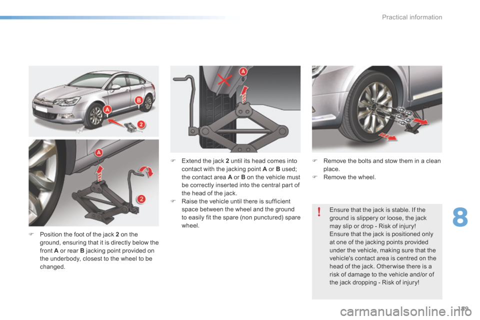
F Position the foot of the jack 2 on the
ground, ensuring that it is directly below the
front A or rear B jacking point provided on
the underbody, closest to the wheel to be
changed. Ensure that the jack is stable. If the
ground is slippery or loose, the jack
may slip or drop - Risk of injury!
Ensure that the jack is positioned only
at one of the jacking points provided
under the vehicle, making sure that the
vehicle's contact area is centred on the
head of the jack. Other wise there is a
risk of damage to the vehicle and/or of
the jack dropping - Risk of injury!
F
Extend the jack 2 until its head comes into
contact with the jacking point A or B used;
the contact area A or B on the vehicle must
be correctly inserted into the central part of
the head of the jack.
F Raise the vehicle until there is sufficient
space between the wheel and the ground
to easily fit the spare (non punctured) spare
wheel. F
Remove the bolts and stow them in a clean
place.
F Remove the wheel.
8
Practical information
Page 193 of 366

191
C5_en_Chap08_information_ed01-2015
If your vehicle is fitted with a spare
wheel of a different size to those on the
vehicle, you must not exceed 50 mph
(80 km/h) whilst using the spare wheel.
The wheel bolts are specific to the type
of wheel.
If the type of wheel is changed,
check with your CITROËN dealer or a
qualified workshop that the wheel bolts
are compatible with the new wheels.
Take care to note down the code
number engraved on the head of the
security bolt socket. This will enable
you to obtain a replacement security
bolt socket from your dealer.
F
Tighten the security bolt using
wheelbrace 1 and security bolt socket
(depending on equipment).
F Tighten the other bolts using just the
wheelbrace 1 .
F Refit the protectors on the bolts.
F Stow the tools in the carrier box.
F Return the suspension to the normal
position.
F Check that the tyre pressure is correct and
have the balancing checked.Tyre under-inflation detection
The space-saver type or steel spare
wheel does not have a sensor.
The punctured wheel must be repaired
by a CITROËN dealer or a qualified
workshop.
8
Practical information
Page 195 of 366

193
C5_en_Chap08_information_ed01-2015
Changing a bulb
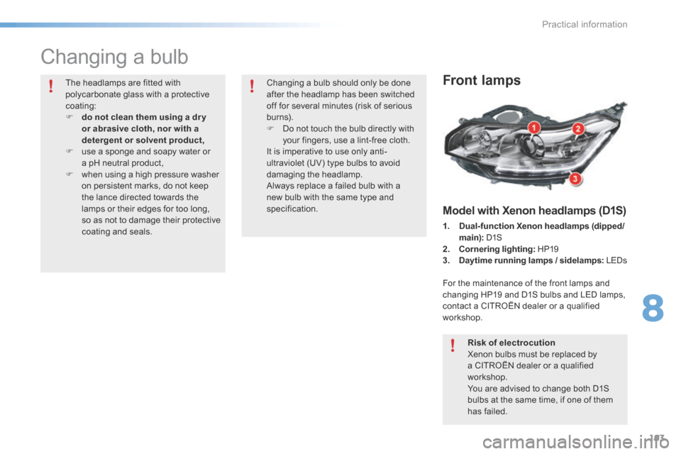
Front lamps
Model with Xenon headlamps (D1S)
1. Dual-function Xenon headlamps (dipped/
main): d1S
2. Cornering lighting: HP19
3. Daytime running lamps / sidelamps: LEd s
For the maintenance of the front lamps and
changing HP19 and D1S bulbs and LED lamps,
contact a CITROËN dealer or a qualified
workshop.
Risk of electrocution
Xenon bulbs must be replaced by
a CITROËN dealer or a qualified
workshop.
You are advised to change both D1S
bulbs at the same time, if one of them
has failed.
The headlamps are fitted with
polycarbonate glass with a protective
coating:
F
do not clean them using a dr y
or abrasive cloth, nor with a
detergent or solvent product,
F use a sponge and soapy water or
a pH neutral product,
F when using a high pressure washer
on persistent marks, do not keep
the lance directed towards the
lamps or their edges for too long,
so as not to damage their protective
coating and seals. Changing a bulb should only be done
after the headlamp has been switched
off for several minutes (risk of serious
burns).
F d
o not touch the bulb directly with
your fingers, use a lint-free cloth.
It is imperative to use only anti-
ultraviolet (UV) type bulbs to avoid
damaging the headlamp.
a lways replace a failed bulb with a
new bulb with the same type and
specification.
8
Practical information
Page 200 of 366

198
C5_en_Chap08_information_ed01-2015
Wing-mounted lamps
F Remove the lateral boot trim flap A . To do
so, pull it towards the inside of the boot,
then pull it upwards.
F d isconnect connector B .
F Unscrew the 2 fixings C .
F Remove the lamp from its housing. F d
etach the bulb holder D .
F Replace the failed bulb.
F Refit the bulb holder D .
F Place the lamp in its housing.
F Screw in the 2 fixings C .
F Refit connector B .
F Refit the side boot trim A .
For vehicles fitted with a Hi-Fi amplifier, on the
right hand side slacken the screw by a quarter
turn, then pull the boot side trim A up. You can use the wheelbrace to screw or
unscrew the fixings C
.
Practical information
Page 202 of 366

200
C5_en_Chap08_information_ed01-2015
Wing-mounted lamps
F Pull away the flap in the boot side trim A .
To do this, pull it towards the middle of the
boot, then pull it up.
F d isconnect the connector B .
F Unscrew the fixing nut C .
F Remove the lamp from its housing. F d
etach the bulb holder D .
F Replace the faulty bulb.
F Refit the bulb holder D .
F Place the lamp in its housing.
F Screw in the fixing nut C .
F Refit the connector B .
F Refit the side boot trim A .
For vehicles fitted with a Hi-Fi amplifier, on the
right hand side slacken the screw by a quarter
turn, then pull the boot side trim A up. You can use the wheelbrace to screw or
unscrew the fixing nut C
.
Practical information