tow bar CITROEN C5 AIRCROSS DAG 2022 Handbook (in English)
[x] Cancel search | Manufacturer: CITROEN, Model Year: 2022, Model line: C5 AIRCROSS DAG, Model: CITROEN C5 AIRCROSS DAG 2022Pages: 276, PDF Size: 7.92 MB
Page 183 of 276
181
In the event of a breakdown
8► Follow the safety instructions (hazard
warning lamps, warning triangle, high visibility
jacket, etc.) according to the legislation in force
in the country in which you are driving.
►
Switch the ignition off.
►
Remove the valve cap from the tyre to be
repaired, and place it in a clean place.
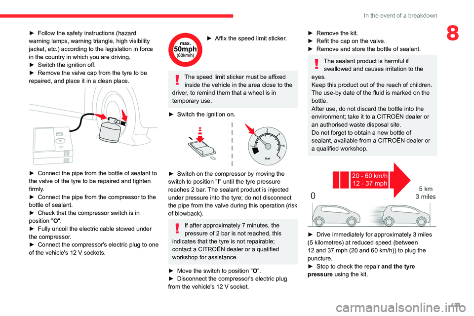
► Connect the pipe from the bottle of sealant to
the valve of the tyre to be repaired and tighten
firmly
.
►
Connect the pipe from the compressor to the
bottle of sealant.
►
Check that the compressor switch is in
position
"O".
►
Fully uncoil the electric cable stowed under
the compressor
.
►
Connect
the compressor's electric plug to one
of the vehicle's 12
V sockets.
► Affix the speed limit sticker .
The speed limit sticker must be affixed
inside the vehicle in the area close to the
driver, to remind them that a wheel is in
temporary use.
►
Switch the ignition on.
► Switch on the compressor by moving the
switch to position " I
" until the tyre pressure
reaches 2 bar. The sealant product is injected
under pressure into the tyre; do not disconnect
the pipe from the valve during this operation (risk
of blowback).
If after approximately 7 minutes, the
pressure of 2 bar is not reached, this
indicates that the tyre is not repairable;
contact a CITROËN dealer or a qualified
workshop for assistance.
►
Move the switch to position " O
".
►
Disconnect the compressor's electric plug
from the vehicle's 12
V socket.
► Remove the kit.
► Refit the cap on the valve.
►
Remove and store the bottle of sealant.
The sealant product is harmful if swallowed and causes irritation to the
eyes.
Keep this product out of the reach of children.
The use-by date of the fluid is marked on the
bottle.
After use, do not discard the bottle into the
environment; take it to a CITROËN dealer or
an authorised waste disposal site.
Do not forget to obtain a new bottle of
sealant, available from a CITROËN dealer or
a qualified workshop.
► Drive immediately for approximately 3 miles
(5 kilometres) at reduced speed (between
12 and 37 mph (20 and 60
km/h)) to plug the
puncture.
►
Stop to check the repair
and the tyre
pressure using the kit.
Page 184 of 276

182
In the event of a breakdown
With a tyre repaired using this type of kit,
do not exceed a speed of 50 mph
(80
km/h) and do not drive more than
125
miles (200 km).
Contact a CITROËN dealer or a qualified
workshop to have the tyre changed.
Checking/adjusting tyre
pressures
The compressor can be used, without injecting
sealant, to check and, if necessary, adjust the
tyre pressures.
►
Remove the valve cap from the tyre and keep
it in a clean place.
►
Uncoil
the pipe stowed under the compressor.
►
Screw the pipe onto the valve and tighten
firmly
.
►
Check that the compressor switch is in
position " O
".
►
Fully uncoil the electric cable stowed under
the compressor
.
►
Connect
the compressor's electric plug to one
of the vehicle's 12
V sockets.
►
Switch the ignition on.
►
Start the compressor by placing the switch at
position " I
" and adjust the pressure to the value
shown on the vehicle's tyre pressure label. To
deflate: press the black button located on the
compressor pipe, near the valve connection.
If after 7 minutes the pressure of 2 bar is
not reached, the tyre is damaged;
contact a CITROËN dealer or a qualified
workshop for assistance.
►
Once the correct pressure is reached, put the
switch in position " O
".
►
Remove the kit and stow it.
►
Refit the cap on the valve.
Spare wheel
Scan the QR Code on page 3 to view
explanatory videos.
For more information on the Tool kit,
refer to the corresponding section.
Accessing the spare wheel
The spare wheel is stored in the boot, under the
floor.
To access the spare wheel, first refer to the
Tool
kit
section.
Depending on version, the spare wheel
may be a standard size steel or alloy
wheel.
In some countries, it is a ‘space saver’ wheel.
Removing the spare wheel
► Slacken the central nut.
► Remove the fastening device (nut and bolt).
►
Lift the spare wheel towards you from the
rear
.
►
T
ake the wheel out of the boot.
Putting the spare wheel back in place
The punctured wheel cannot be put under the boot floor.
► Put the spare wheel back in place in its
housing.
► Slacken the nut on the bolt by a few turns.
► Position the fastening device (nut and bolt) in
the middle of the wheel.
► Tighten the central nut sufficiently to retain
the wheel correctly.
► Put the tool box back in place in the middle of
the wheel and clip it in place.
If there is no wheel in the well, the
fastening device (nut and bolt) cannot be
refitted.
Removing a wheel
Parking the vehicle
Immobilise the vehicle where it does
not obstruct traffic: the ground must be level,
stable and non-slippery.
With a manual gearbox, engage first gear
to lock the wheels, apply the parking brake,
unless it is set to automatic mode, and switch
off the ignition.
Page 201 of 276
199
In the event of a breakdown
8
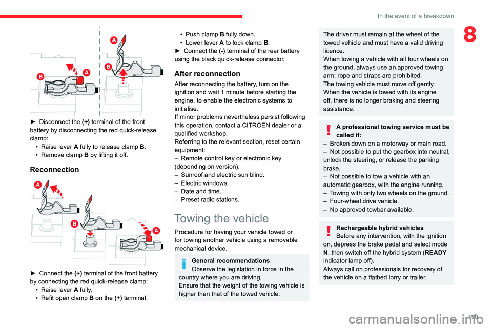
► Disconnect the (+) terminal of the front
battery by disconnecting the red quick-release
clamp: •
Raise lever
A
fully to release clamp
B
.
•
Remove clamp
B
by lifting it off.
Reconnection
► Connect the (+) terminal of the front battery
by connecting the red quick-release clamp: •
Raise lever
A
fully.
•
Refit open clamp
B
on the (+) terminal.
• Push clamp B fully down.
• Lower lever A to lock clamp B.
►
Connect the
(-) terminal of the rear battery
using the black quick-release connector.
After reconnection
After reconnecting the battery, turn on the
ignition and wait 1 minute before starting the
engine, to enable the electronic systems to
initialise.
If minor problems nevertheless persist following
this operation, contact a CITROËN dealer or a
qualified workshop.
Referring to the relevant section, reset certain
equipment:
–
Remote control key or electronic key
(depending on version).
–
Sunroof and electric sun blind.
–
Electric windows.
–
Date and time.
–
Preset radio stations.
Towing the vehicle
Procedure for having your vehicle towed or
for towing another vehicle using a removable
mechanical device.
General recommendations
Observe the legislation in force in the
country where you are driving.
Ensure that the weight of the towing vehicle is
higher than that of the towed vehicle.
The driver must remain at the wheel of the
towed vehicle and must have a valid driving
licence.
When towing a vehicle with all four wheels on
the ground, always use an approved towing
arm; rope and straps are prohibited.
The towing vehicle must move off gently.
When the vehicle is towed with its engine
off, there is no longer braking and steering
assistance.
A professional towing service must be
called if:
–
Broken down on a motorway or main road.
–
Not possible to put
the gearbox into neutral,
unlock the steering, or release the parking
brake.
–
Not possible to tow a vehicle with an
automatic gearbox, with the engine running.
–
T
owing with only two wheels on the ground.
–
Four-wheel drive vehicle.
–
No approved towbar available.
Rechargeable hybrid vehicles
Before any intervention, with the ignition
on, depress the brake pedal and select mode
N, then switch off the hybrid system (READY
indicator lamp off).
Always call on professionals for recovery of
the vehicle on a flatbed lorry or trailer.
Page 202 of 276
200
In the event of a breakdown
Use the towing eye only to free the vehicle
if it is stuck, or to secure it for recovery on a
flatbed lorry or trailer.
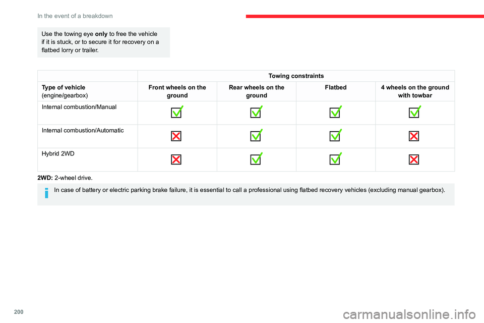
Towing constraints
Type of vehicle
(engine/gearbox) Front wheels on the
ground Rear wheels on the
ground Flatbed
4 wheels on the ground
with towbar
Internal combustion/Manual
Internal combustion/Automatic
Hybrid 2WD
2WD: 2-wheel drive.
In case of battery or electric parking brake failure, it is essential to call a p
rofessional using flatbed recovery vehicles (excluding manual gearbox).
Accessing the tools
The towing eye is stored in a tool box, under the
boot floor.
The opening tool for the rear protective cover is
secured to the towing eye.
For more information on accessing the Tool kit,
refer to the corresponding section.
Towing your vehicle
To access the front screw thread:
Page 203 of 276
201
In the event of a breakdown
8Accessing the tools
The towing eye is stored in a tool box, under the
boot floor.
The opening tool for the rear protective cover is
secured to the towing eye.
For more information on accessing the Tool kit,
refer to the corresponding section.
Towing your vehicle
To access the front screw thread:
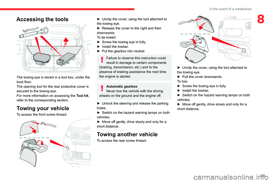
► Unclip the cover , using the tool attached to
the towing eye.
►
Release the cover to the right and then
downwards.
T
o be towed:
►
Screw the towing eye in fully
.
►
Install the towbar
.
►
Put the gearbox into neutral.
Failure to observe this instruction could
result in damage to certain components
(braking, transmission, etc.) and to the
absence of braking assistance the next time
the engine is started.
Automatic gearbox
Never tow the vehicle with the driving
wheels on the ground and the engine off.
►
Unlock the steering and release the parking
brake.
►
Switch on the hazard warning lamps on both
vehicles.
►
Move off gently
, drive slowly and only for a
short distance.
Towing another vehicle
To access the rear screw thread:
► Unclip the cover , using the tool attached to
the towing eye.
►
Pull the cover downwards.
T
o tow:
►
Screw the towing eye in fully
.
►
Install the towbar
.
►
Switch on the hazard warning lamps on both
vehicles.
►
Move off gently
, drive slowly and only for a
short distance.
Page 252 of 276
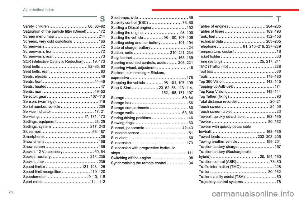
250
Alphabetical index
S
Safety, children 86, 88–92
Saturation of the particle filter (Diesel)
172
Screen menu map
214
Screens, very cold conditions
166
Screenwash
72
Screenwash, front
72
Screenwash, rear
73
SCR (Selective Catalytic Reduction)
19, 173
Seat belts
82–85, 90
Seat belts, rear
83
Seats, electric
46
Seats, front
44–46
Seats, heated
47
Seats, rear
49–50
Selector, gear
107–110
Sensors (warnings)
11 8
Serial number, vehicle
206
Service indicator
17, 21
Servicing
17, 171, 173
Settings, equipment
23, 25
Settings, system
217, 240
Sidelamps
68, 187
Smartphone
26
Snow chains
166
Snow screen
166
Socket, 12 V accessory
60, 64
Socket, auxiliary
213, 235
Socket, Jack
235
Speed limiter
121–123, 125
Speed limit recognition
119–120
Speedometer
9–10, 118
Sport mode
111 – 11 2
Spotlamps, side 69
Stability control (ESC)
78, 80
Starting a Diesel engine
152
Starting the engine
98, 100
Starting the vehicle
98–100, 107–109
Starting using another battery
101, 194
State of charge, battery
24
Station, radio
210–211, 234
Stay, bonnet
168–169
Steering mounted controls, audio
208, 221
Steering wheel, adjustment
48
Stickers, customising ~ Stickers,
expressive
176
Stopping the vehicle
98–101, 107–109
Stop & Start
23, 52, 56, 113–114, 152, 168, 171, 197
Storage
60–64
Storage box
66
Storage compartments
60
Storage wells
63, 66
Storing driving positions
46
Stowing rings
63
Sunroof, panoramic
42–43
Sunshine sensor
51
Sun visor
60
Suspension
173
Suspension with progressive hydraulic
stops
111
Switching off the engine
98
Synchronising the remote control
34T
Tables of engines 204–205
Tables of fuses
189, 193
Tank, fuel
152–153
Technical data
203–205
Telephone
61, 215–216, 237–239
Temperature, coolant
18
Ticket holder
60
Time (setting)
25, 217, 241
TMC (Traffic info)
228
Tool box
66
Tools
178–180
Top 360 Vision
143, 145
Topping-up AdBlue®
174
Top Rear Vision
143–144
Top Tether (fixing)
90
Total distance recorder
20–21
Touch screen
24, 59
Touch screen tablet
23
Towball, quickly detachable
163–165
Towbar
80, 162
Towbar with quickly detachable
towball
163–165
Towed loads
202–203, 205
Towing another vehicle
199, 201
Traction battery charge
157
Traction battery (Rechargeable
hybrid)
20, 154, 160
Traction control (ASR)
78–80
Traffic information (TMC)
228
Trailer
80, 162
Trailer stability assist (TSA)
80
Trajectory control systems
78