boot Citroen C5 RHD 2014.5 (RD/TD) / 2.G Owner's Guide
[x] Cancel search | Manufacturer: CITROEN, Model Year: 2014.5, Model line: C5 RHD, Model: Citroen C5 RHD 2014.5 (RD/TD) / 2.GPages: 344, PDF Size: 12.9 MB
Page 180 of 344

178
"ISOFIX" mountings
Your vehicle has been approved in accordance
with the latest ISOFIX regulations.
The outer rear seats are fitted with regulation
ISOFIX mountings.
There are three rings for each outer rear seat:
-
t
wo lower rings A, located between the
vehicle seat back and cushion, indicated by
a marking,
-
a
n upper ring B, called the TOP TETHER ,
fixed to the rear shelf and located under a
cover behind the head restraint behind the
head restraint, for fixing the upper strap.
I
t is indicated by a marking.There are three rings for each outer rear seat:
-
t
wo lower rings A, located between the
vehicle seat back and cushion, indicated by
a marking,
-
a
n upper ring C, called the TOP TETHER ,
fixed to the roof on the boot end and
located under a cover, for fixing the upper
strap.
I
t is indicated by a marking.SaloonTourer
Child safety
Page 190 of 344

188
Temporary puncture repair kit
The kit is located in the boot under the floor.
Complete system consisting of a compressor
and a sealant cartridge which permits the
temporary repair
of the tyre so that you can
drive to the nearest garage. This repair kit is available from
CITROËN dealers or a qualified
workshop.
It is designed to repair holes of a
maximum diameter of 6 mm, located
exclusively on the tyre tread or
shoulder. Avoid removing any foreign
bodies which have penetrated the tyre.
The vehicle's electric system allows the
connection of a compressor for long
enough to inflate a tyre after a puncture
repair or for inflating a small inflatable
accessory.
Practical information
Page 195 of 344

193
Access to the spare wheel
To remove the spare wheel
F Saloon: raise the boot floor and fold in two.
F T ourer: raise the boot floor and hook it
using the retractable handle. Secure the
hook to the top part of the boot.
F
d
e
tach the strap then push the wheel
for wards so as to be able to lift it.
To reposition the spare wheel
F Position the spare wheel flat in the boot, then pull it towards you.
F
N
ext place the toolbox inside the wheel,
then secure the assembly with the strap.
F
R
elease the boot floor to return it to its
initial position. The tyre pressures are indicated on the
label located on the driver's side centre
door pillar. Tyre pressures are given for
different vehicle loading conditions.
8
Practical information
Page 205 of 344

203
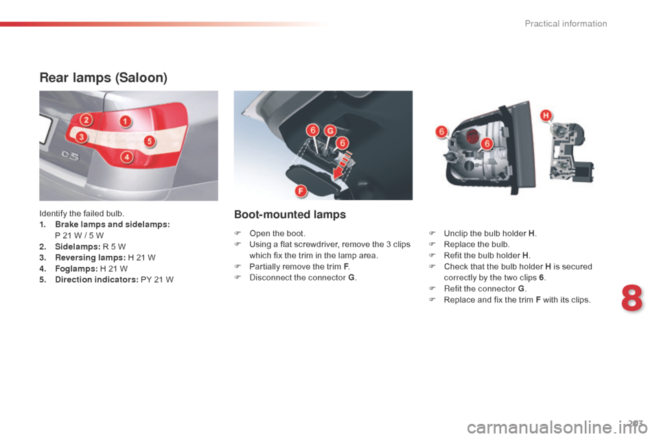
Rear lamps (Saloon)
Identify the failed bulb.
1. Brake lamps and sidelamps:
P 21 W
/ 5 W
2.
S
idelamps: R 5 W
3.
R
eversing lamps: H 21 W
4.
F
oglamps: H 21 W
5.
D
irection indicators: PY 21 WBoot-mounted lamps
F Unclip the bulb holder H .
F R eplace the bulb.
F
R
efit the bulb holder H .
F
C
heck that the bulb holder H is secured
correctly by the two clips 6 .
F
R
efit the connector G .
F
R
eplace and fix the trim F with its clips.
F
O
pen the boot.
F
U
sing a flat screwdriver, remove the 3
clips
which fix the trim in the lamp area.
F
P
artially remove the trim F .
F
d
i
sconnect the connector G .
8
Practical information
Page 206 of 344

204
Wing-mounted lamps
F disconnect connector B.
F U nscrew the 2 fixings C .
F
R
emove the lamp from its housing. F
D
etach the bulb holder D
.
F
R
eplace the bulb.
F
R
efit the bulb holder D
.
F
P
lace the lamp in its housing.
F
S
crew in the 2 fixings C
.
F
R
efit connector B
.
F
R
efit the trim A
.
You can use the wheelbrace to screw or
unscrew the fixings C .
F
R
emove the lateral boot trim flap
A . To do
so, pull it towards the inside of the boot,
then pull it upwards.
Practical information
Page 207 of 344

205
Boot-mounted lamps
Rear lamps (Tourer)
Identify the failed bulb.
1. Brake lamps and sidelamps:
P 21 W
/ 5 W
2.
S
idelamps: R 5 W
3.
R
eversing lamps: H 21 W
4.
F
oglamps: H 21 W
5.
D
irection indicators: PY 21 W F
U
nclip the bulb holder J.
F
R
eplace the bulb.
F
R
efit the bulb holder J ensuring that it is
correctly clipped in place.
F
P
osition the lamp in its housing.
F
T
ighten the fixing nut H.
F
R
efit the connector G.
F
P
osition and clip in place the plastic
cover F .
You can use the wheelbrace to screw or
unscrew the fixing nut H .
F
O
pen the boot.
F
U
sing a flat screwdriver, remove the plastic
cover F .
F
d
i
sconnect the connector G.
F
U
nscrew the fixing nut H.
F
D
isengage the lamp from its housing.
8
Practical information
Page 208 of 344

206
Wing-mounted lamps
F disconnect the connector B.
F U nscrew the fixing nut C .
F
R
emove the lamp from its housing. F
D
etach the bulb holder D
.
F
R
eplace the faulty bulb.
F
R
efit the bulb holder D
.
F
P
lace the lamp in its housing.
F
S
crew in the fixing nut C
.
F
R
efit the connector B
.
F
R
efit the trim A
.
You can use the wheelbrace to screw or
unscrew the fixing nut C .
Remove the lateral boot trim A .
To do so:
F
Pull it towards towards the inside of the boot.F Pull it upwards.
Practical information
Page 210 of 344

208
Interior lamps
Roof lamps
F Unclip the transparent cover of the roof lamp to reach the bulb.
Bulb: W 5 W
Rear reading lamps (Tourer)
F Detach the cover of the reading lamp to
access the bulb.
Bulb: W 5 W
Map reading lamp
F Detach the cover.
F
I f necessary, detach the partition of
the
affected map reading lamp.
Boot lamp
F Detach the cover and use a W 5W bulb.
Practical information
Page 215 of 344

213
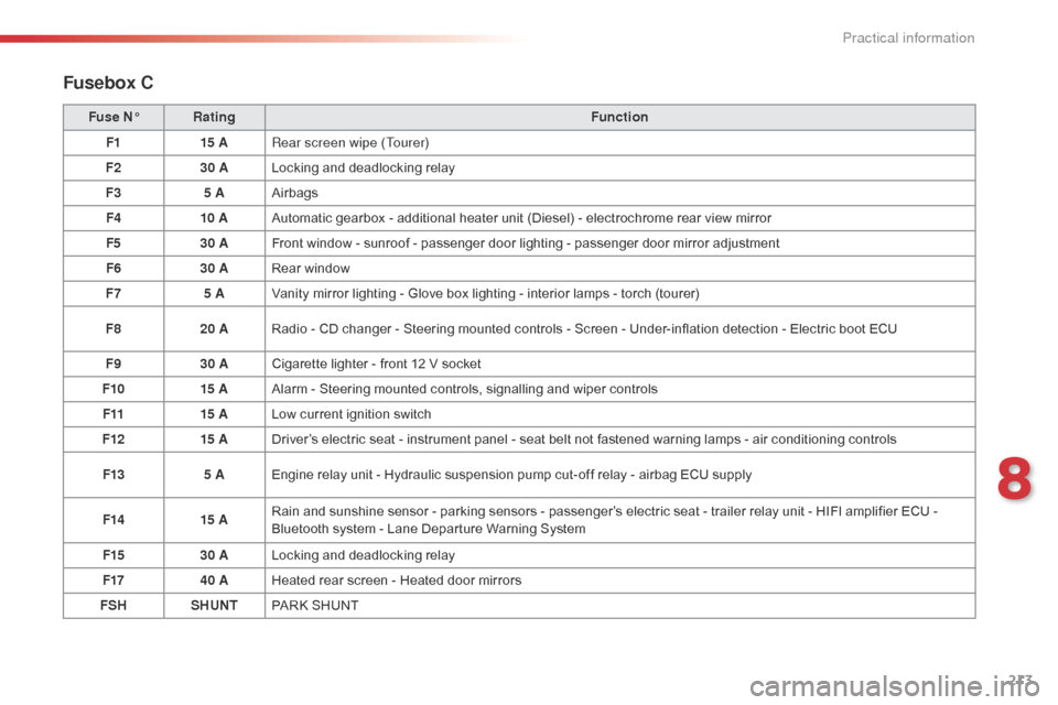
Fusebox C
Fuse N°Rating Function
F1 15 ARear screen wipe (Tourer)
F2 30 ALocking and deadlocking relay
F3 5 AAirbags
F4 10 AAutomatic gearbox - additional heater unit (Diesel) - electrochrome rear view mirror
F5 30 AFront window - sunroof - passenger door lighting - passenger door mirror adjustment
F6 30 ARear window
F7 5 AVanity mirror lighting - Glove box lighting - interior lamps - torch (tourer)
F8 20 ARadio - CD changer - Steering mounted controls - Screen - Under-inflation detection - Electric boot ECU
F9 30 ACigarette lighter - front 12 V socket
F10 15 AAlarm - Steering mounted controls, signalling and wiper controls
F11 15 ALow current ignition switch
F12 15 ADriver’s electric seat - instrument panel - seat belt not fastened warning lamps - air conditioning controls
F13 5 AEngine relay unit - Hydraulic suspension pump cut-off relay - airbag ECU supply
F14 15 ARain and sunshine sensor - parking sensors - passenger’s electric seat - trailer relay unit - HIFI amplifier ECU -
Bluetooth system - Lane Departure Warning System
F15 30 ALocking and deadlocking relay
F17 40 AHeated rear screen - Heated door mirrors
FSH SHUNTPARK SHUNT
8
Practical information
Page 222 of 344

220
Towing the vehicle
Access to the tools
The towing eye is installed in the jack box
placed in the spare wheel.
For access to it:
F
o
pen the boot,
F
r
aise the floor,
F
r
emove the towing eye from the jack box.
Procedure for having your vehicle towed or for towing another vehicle using a removable towing eye.
Towing your vehicle
F On the front bumper, unclip the cover by
pressing at the top.
F
S
crew the towing eye in fully.
F
A
ttach a towing arm.
F
S
witch on the hazard warning lamps on the
towed vehicle.
F
P
lace the gear lever in neutral (position N
on the automatic gearbox). Failure to observe this special condition
could result in damage to certain
braking components and the absence
of braking assistance the next time the
engine is started.
In the event of a problem or malfunction
with the electronic gearbox, the vehicle
may be immobilised with a gear
engaged. In this case the front of the
vehicle must be lifted for towing.
Practical information