check engine CITROEN C6 2005 Owner's Guide
[x] Cancel search | Manufacturer: CITROEN, Model Year: 2005, Model line: C6, Model: CITROEN C6 2005Pages: 223, PDF Size: 4.26 MB
Page 86 of 223
Downloaded from www.Manualslib.com manuals search engine 80
ENGINE
DRAINING, FILLING AND BLEEDING THE ENGINE COOLING CIRCUIT
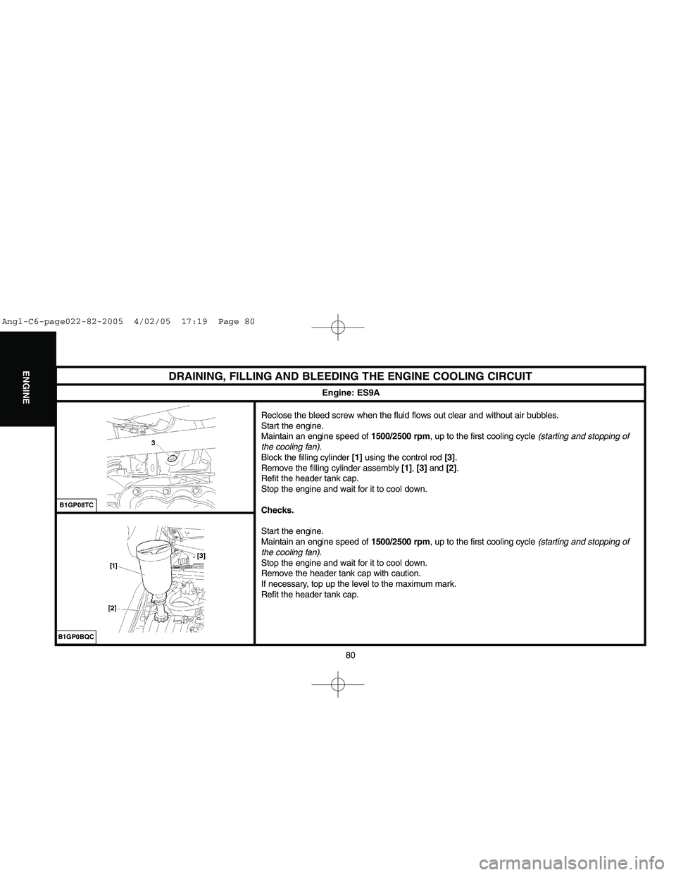
Reclose the bleed screw when the fluid flows out clear and without air bubbles.
Start the engine.
Maintain an engine speed of 1500/2500 rpm, up to the first cooling cycle (starting and stopping of
the cooling fan).
Block the filling cylinder [1]using the control rod [3].
Remove the filling cylinder assembly [1], [3]and [2].
Refit the header tank cap.
Stop the engine and wait for it to cool down.
Checks.
Start the engine.
Maintain an engine speed of 1500/2500 rpm, up to the first cooling cycle (starting and stopping of
the cooling fan).
Stop the engine and wait for it to cool down.
Remove the header tank cap with caution.
If necessary, top up the level to the maximum mark.
Refit the header tank cap.
B1GP08TC
Engine: ES9A
B1GP0BQC
Angl-C6-page022-82-2005 4/02/05 17:19 Page 80
Page 88 of 223
Downloaded from www.Manualslib.com manuals search engine 82
ENGINE
DRAINING, FILLING AND BLEEDING THE ENGINE COOLING CIRCUIT
Filling and bleeding.
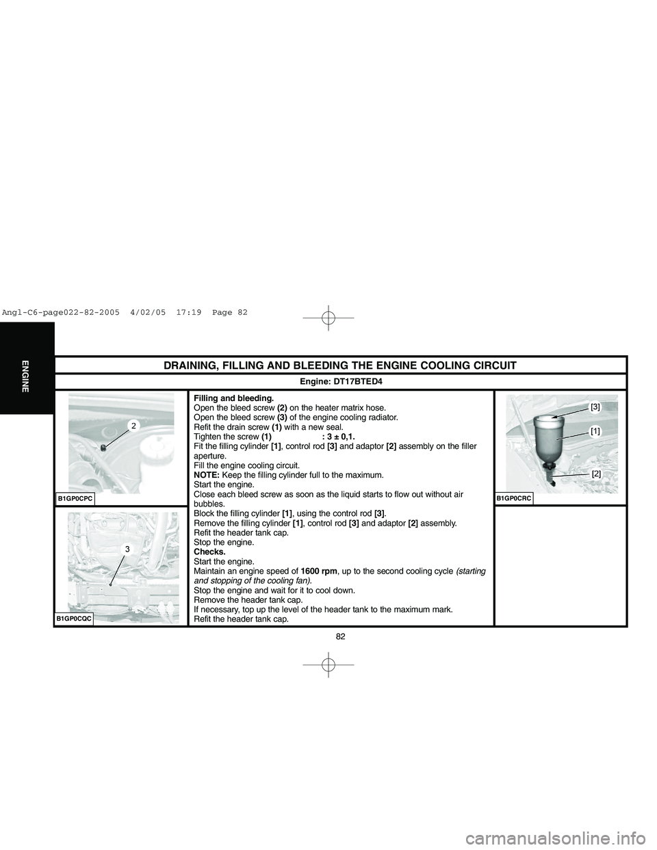
Open the bleed screw (2)on the heater matrix hose.
Open the bleed screw (3)of the engine cooling radiator.
Refit the drain screw (1)with a new seal.
Tighten the screw (1) : 3 ± 0,1.
Fit the filling cylinder [1], control rod [3]and adaptor [2]assembly on the filler
aperture.
Fill the engine cooling circuit.
NOTE:Keep the filling cylinder full to the maximum.
Start the engine.
Close each bleed screw as soon as the liquid starts to flow out without air
bubbles.
Block the filling cylinder [1], using the control rod [3].
Remove the filling cylinder [1], control rod [3]and adaptor [2] assembly.
Refit the header tank cap.
Stop the engine.
Checks.
Start the engine.
Maintain an engine speed of 1600 rpm, up to the second cooling cycle (starting
and stopping of the cooling fan).
Stop the engine and wait for it to cool down.
Remove the header tank cap.
If necessary, top up the level of the header tank to the maximum mark.
Refit the header tank cap.
Engine: DT17BTED4
B1GP0CQCB1GP0CPC
B1GP0CRC
Angl-C6-page022-82-2005 4/02/05 17:19 Page 82
Page 99 of 223
![CITROEN C6 2005 Owners Guide Downloaded from www.Manualslib.com manuals search engine 93
INJECTION
CHECKS: LOW PRESSURE FUEL SUPPLY CIRCUIT
Engine: DT17BTED4
Tools.
[1] Ø 10 mmlow pressure connector: 4215-T
[2] Ø 8 mmlow pressu CITROEN C6 2005 Owners Guide Downloaded from www.Manualslib.com manuals search engine 93
INJECTION
CHECKS: LOW PRESSURE FUEL SUPPLY CIRCUIT
Engine: DT17BTED4
Tools.
[1] Ø 10 mmlow pressure connector: 4215-T
[2] Ø 8 mmlow pressu](/img/9/57744/w960_57744-98.png)
Downloaded from www.Manualslib.com manuals search engine 93
INJECTION
CHECKS: LOW PRESSURE FUEL SUPPLY CIRCUIT
Engine: DT17BTED4
Tools.
[1] Ø 10 mmlow pressure connector: 4215-T
[2] Ø 8 mmlow pressure connector: 4218-T
[3]Pressure gauge for testing boost pressure: 4073-T Kit 4073-T
[4]Extension: 4251-T
Checks.
IMPERATIVE : Respect the safety and cleanliness requirements specific to high pressure
diesel injection (HDi) engines.
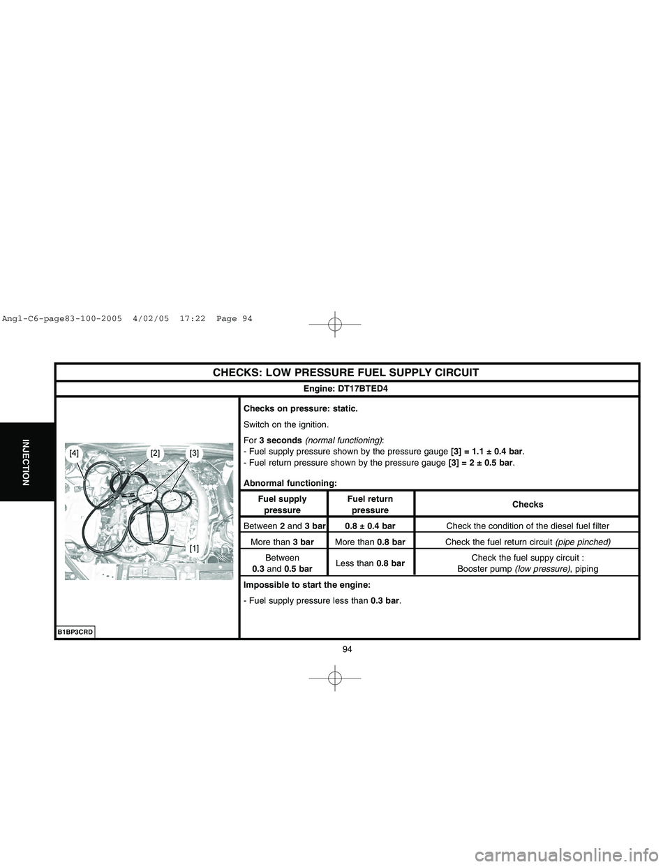
Connect the tool [1]between the booster pump and the fuel filter (white mark on the fuel supply
pipe).
Connect the tool [2]downstream of the diesel injectors, between the high pressure fuel pump and
the fuel filter green mark on the fuel return pipe.
Connect the tool [3]on tool [1]or on tool [2].
WARNING: Any check of pressure downstream of the fuel filter is prohibited.
NOTE:To check the pressures while the vehicle is being driven, insert the extension [4] between
tool [3]and tools [1]or [2].
B1BP3CRD
Angl-C6-page83-100-2005 4/02/05 17:22 Page 93
Page 100 of 223
Downloaded from www.Manualslib.com manuals search engine 94
INJECTION
CHECKS: LOW PRESSURE FUEL SUPPLY CIRCUIT
Engine: DT17BTED4
Checks on pressure: static.
Switch on the ignition.
For 3 seconds(normal functioning):
- Fuel supply pressure shown by the pressure gauge[3] = 1.1 ± 0.4 bar.
- Fuel return pressure shown by the pressure gauge [3] = 2 ± 0.5 bar.
Abnormal functioning:
Fuel supply Fuel return
Checks
pressure pressure
Between 2and 3 bar 0.8 ± 0.4 barCheck the condition of the diesel fuel filter
More than 3 barMore than 0.8 barCheck the fuel return circuit (pipe pinched)
Between
Less than 0.8 barCheck the fuel suppy circuit :
0.3and 0.5 barBooster pump (low pressure), piping
Impossible to start the engine:
- Fuel supply pressure less than 0.3 bar.
B1BP3CRD
Angl-C6-page83-100-2005 4/02/05 17:22 Page 94
Page 101 of 223
![CITROEN C6 2005 Owners Guide Downloaded from www.Manualslib.com manuals search engine 95
INJECTION
CHECKS: TURBO PRESSURE
Engine: DT17BTED4
Tools.
[1]Pressure gauge for checking the pressure: 7073-T.A
[2]Tool for checking the inl CITROEN C6 2005 Owners Guide Downloaded from www.Manualslib.com manuals search engine 95
INJECTION
CHECKS: TURBO PRESSURE
Engine: DT17BTED4
Tools.
[1]Pressure gauge for checking the pressure: 7073-T.A
[2]Tool for checking the inl](/img/9/57744/w960_57744-100.png)
Downloaded from www.Manualslib.com manuals search engine 95
INJECTION
CHECKS: TURBO PRESSURE
Engine: DT17BTED4
Tools.
[1]Pressure gauge for checking the pressure: 7073-T.A
[2]Tool for checking the inlet air pressure/vacuum: (-).0171.G3
[3] LEXIAdiagnostic tool: 4171-T
[4] PROXIAdiagnostic tool: 4165-T
Checks.
IMPERATIVE: Respect the safety and cleanliness specific to high pressure diesel injection
engines.
Preliminary operations.
WARNING: Prior to any intervention, check the connections of the turbocharger pressure
regulation actuators.
NOTE:If an air flow fault is memorised by the diagnostic tool, refer to the chapter "Air flow from
the turbochargers".
Turbo pressure sensor.
Remove the engine cover.
Disconnect the connector "a".
Remove the turbo pressure sensor (1).
B1BP3CZC
Angl-C6-page83-100-2005 4/02/05 17:22 Page 95
Page 102 of 223
![CITROEN C6 2005 Owners Guide Downloaded from www.Manualslib.com manuals search engine 96
INJECTION
CHECKS: TURBO PRESSURE
Engine: DT17BTED4
Connect:
- The tool [2a]in place of the turbo pressure sensor (1).
- The turbo pressure s CITROEN C6 2005 Owners Guide Downloaded from www.Manualslib.com manuals search engine 96
INJECTION
CHECKS: TURBO PRESSURE
Engine: DT17BTED4
Connect:
- The tool [2a]in place of the turbo pressure sensor (1).
- The turbo pressure s](/img/9/57744/w960_57744-101.png)
Downloaded from www.Manualslib.com manuals search engine 96
INJECTION
CHECKS: TURBO PRESSURE
Engine: DT17BTED4
Connect:
- The tool [2a]in place of the turbo pressure sensor (1).
- The turbo pressure sensor (1)on the tool [2b].
- Tool [1]on tool [2], at "b".
Connect the diagnostic tool [3]or [4]to the vehicle's diagnostic socket:
- Put the diagnostic tool [3]or [4]in parameter measures.
Start the engine.
Accelerate to 2500 rpm.
Compare the pressure values read on the diagnostic tool and on the pressure gauge [1].
NOTE:If there is a significant difference in pressure, replace the turbo pressure sensor.
Air/air exhanger.
Check the condition of the following components:
- Air inlet pipe.
- Airoutlet pipe.
- Air /air exchanger.
Air flow from the turbochargers.
NOTE: If an air flow fault is memorised by the diagnostic tool, check the air flow from the turbocharger
incriminated.
Connect the diagnostic tool [3]or [4]to the vehicle's diagnostic socket:
- Put the diagnostic tool [3]or [4]in parameter measures.
Start the engine.
Accelerate to 2500 rpm.
Compare the air flows (mg/stroke)from the two turbochargers.
B1BP3D0C
Angl-C6-page83-100-2005 4/02/05 17:22 Page 96
Page 103 of 223
Downloaded from www.Manualslib.com manuals search engine 97
INJECTION
CHECKS: TURBO PRESSURE
Engine: DT17BTED4
Significant difference in pressure between the two turbochargers:
- Stop the engine.
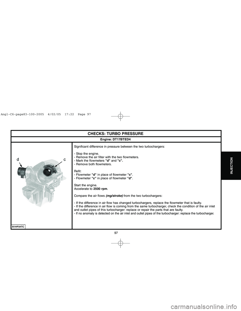
- Remove the air filter with the two flowmeters.
- Mark the flowmeters "d"and "c".
- Remove both flowmeters.
Refit:
- Flowmeter "d"in place of flowmeter "c".
- Flowmeter "c"in place of flowmeter "d".
Start the engine.
Accelerate to 2500 rpm.
Compare the air flows (mg/stroke)from the two turbochargers:
- If the difference in air flow has changed turbochargers, replace the flowmeter that is faulty.
- If the difference in air flow is coming from the same turbocharger, check the condition of the air inlet
and outlet pipes of this turbocharger: replace or repair the parts that are faulty.
- If no anomaly is detected on the air inlet and outlet pipes of the turbocharger: replace the turbocharger.
B1HP24TC
Angl-C6-page83-100-2005 4/02/05 17:22 Page 97
Page 104 of 223
Downloaded from www.Manualslib.com manuals search engine 98
INJECTION
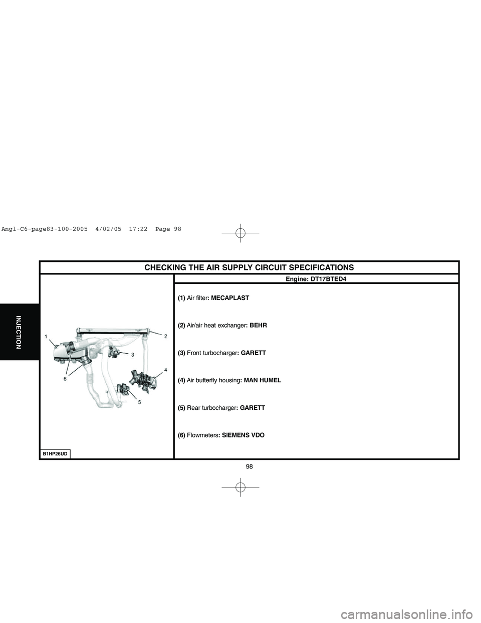
CHECKING THE AIR SUPPLY CIRCUIT SPECIFICATIONS
Engine: DT17BTED4
(1) Air filter: MECAPLAST
(2)Air/air heat exchanger: BEHR
(3) Front turbocharger: GARETT
(4)Air butterfly housing: MAN HUMEL
(5)Rear turbocharger: GARETT
(6)Flowmeters: SIEMENS VDO
B1HP26UD
Angl-C6-page83-100-2005 4/02/05 17:22 Page 98
Page 105 of 223
![CITROEN C6 2005 Owners Guide Downloaded from www.Manualslib.com manuals search engine 99
INJECTION
CHECKING THE AIR SUPPLY CIRCUIT
Tool.
[1]Manual pressure-vacuum pump : FACOM DA 16
Checks.
IMPERATIVE: Respect the safety and clea CITROEN C6 2005 Owners Guide Downloaded from www.Manualslib.com manuals search engine 99
INJECTION
CHECKING THE AIR SUPPLY CIRCUIT
Tool.
[1]Manual pressure-vacuum pump : FACOM DA 16
Checks.
IMPERATIVE: Respect the safety and clea](/img/9/57744/w960_57744-104.png)
Downloaded from www.Manualslib.com manuals search engine 99
INJECTION
CHECKING THE AIR SUPPLY CIRCUIT
Tool.
[1]Manual pressure-vacuum pump : FACOM DA 16
Checks.
IMPERATIVE: Respect the safety and cleanliness specific to high pressure
diesel injection engines.
Checking the vacuum source (vacuum pump).
Connect the tool [1]on the take-off "a"of the vacuum pump (1).
Start the engine.
The value should be 0,85 ± 0,2 bar.
"Swirl" control electrovalve.
Connect the tool [1]on the vacuum supply "b"of the electrovalve (2).
Start the engine.
The value should be 0,85 ± 0,2 bar.
"Swirl" control diaphragm.
Connect the tool [1]on the "Swirl"control diaphragms (3)at "c".
Apply a vacuum of approx. 0,7 ± 0,2 bar, the "Swirl"butterfly should be fully
open.
Engine: DT17BTED4
B1HP26ECB1HP26DC
B1HP26FC
Angl-C6-page83-100-2005 4/02/05 17:22 Page 99
Page 107 of 223

Downloaded from www.Manualslib.com manuals search engine 101
CLUTCH
GEARBOX
TRANSMISSION
SPEEDOMETER
An E.E.C. decree of 25 June 1976, regulates the speed displayed by the speedmeter in relation to the actual speed travelled.
This decree stipulates:
- The speed indicated by a speedometer must never be lower than the actual vehicle speed.
- Between the speed displayed «SD»and the speed travelled «ST», there must always be the following relationship:
ST < SD < 1.10 ST + 4 Kph
Example:For an actual speed of 100 Kphthe speed displayed by the speedometer may be between 100and 11 4 K p h.
The speed indicated by the speedometer may be influenced by:
- The speedometer.
- The tyres fitted to the vehicle.
- The final drive ratio.
- The speedometer drive ratio.
Any of these components can be checked without removing them from the vehicle (see information note N° 78-85 TT of 19 October 1978).
NOTE:Before replacing the speedometer, check the conformity of the following points:
- The tyres fitted to the vehicle.
- The gearbox final drive ratio.
- The speedometer drive ratio.
Angl-C6-page101-120-2005 4/02/05 17:25 Page 101