open bonnet Citroen CX 1974 1.G Workshop Manual
[x] Cancel search | Manufacturer: CITROEN, Model Year: 1974, Model line: CX, Model: Citroen CX 1974 1.GPages: 394
Page 364 of 394

Downloaded from www.Manualslib.com manuals search engine IV. DISTRIBUTION FLAP ( Vl) CONTROL
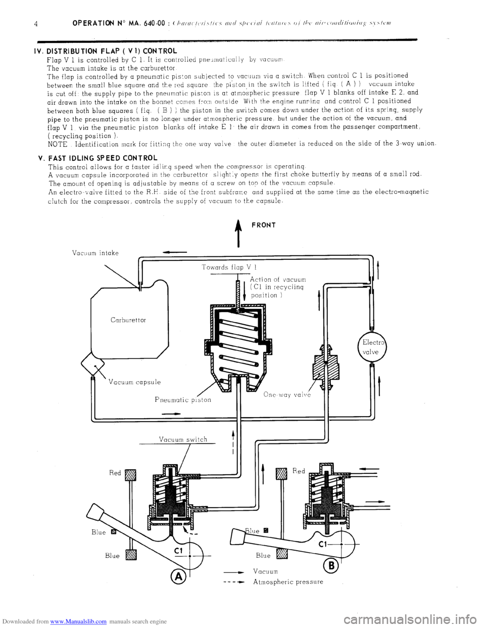
Flap V 1 is controlled by C 1. It is controlled pneumatically by vacuurr
The vacuum intake is at the carburettor
The flap is controlled by a pneumatic piston subjected to vacrrum via a switch When control C 1 is positioned
between the small blue square and the red square the piston,in the switch is lifted ( fiq ( A ) ) vacuum intake
is cut off’ the supply pipe to the pneumatic piston is at atmospheric pressure flap V 1 blanks off intake E 2, and
air drawn into the intake on the bonnet comes from outside With the engine runninc and control C 1 positioned
between both blue squares ( fiq. ( B ) ) the piston in the switch comes down under the action of its spring.
supply
pipe to the pneumatic piston is no lonqer under atmospheric pressure but under the action of the vacuum, and
flap V 1 via the pneumatic piston blanks off intake E 1’ the air drawn in comes from the passenqer compartment,
( recycling position ).
NOTE Identification mark for fittinq the one way valve the outer diameter is reduced on the side of the 3-way union V. FAST IDLING SPEED CONTROL
This control allows for a faster idling speed when the compressor is operatinq
A vacuum capsule incorporated in the carburettor slightly opens the first choke butterfly by means of a small rod.
The amount of opening is adjustable by means of a screw on top of the vacuum capsule.
An electromvalve fitted to the R.H side of the front subframe and supplied at the same time as the electro-maqnetic
clutch for the compressor controls the supply of vacuum to the capsule. t FRONT
Vacuum intake
Carburettor /
Vacuum capsule
Pneumatic p Towards flap V 1
Action of vacuum
I (Cl in recyclinq
position 1
vale
Vacuum switch
7 1
- Vacuum
-- - - Atmospheric pressure
Page 387 of 394

Downloaded from www.Manualslib.com manuals search engine OPERATION No MA. 852-O : Adius/ir,y I/><, bo,,r,r/ Op. MA. 852-O 1
~.
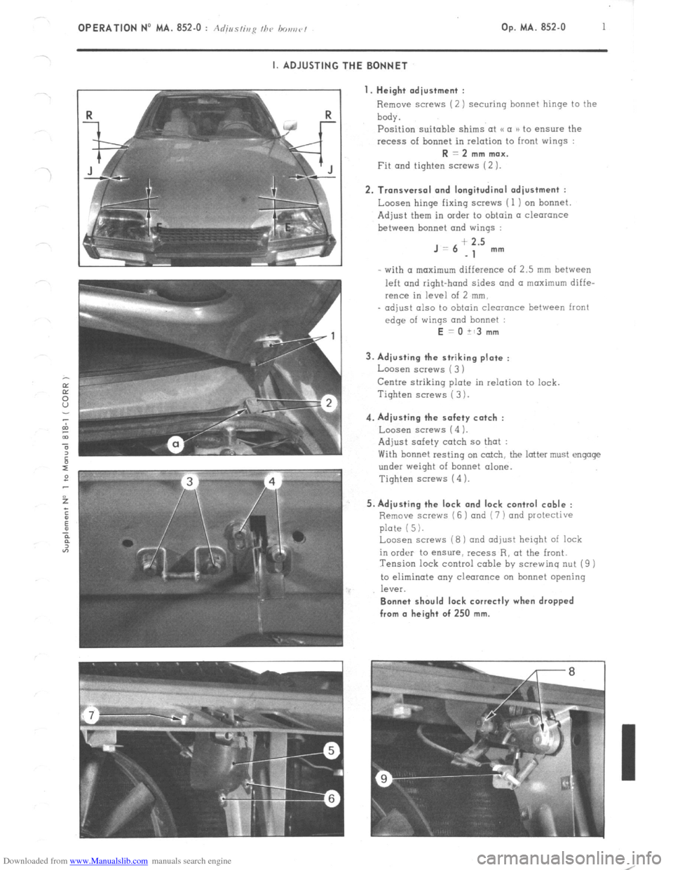
I. ADJUSTING THE BONNET
I. Height adjustment :
Remove screws (2) securing bonnet hinge to the
body.
Position suitable shims at u a )) to ensure the
recess of bonnet in relation to front wings : R = 2 mm max.
Fit and tighten screws (2 ). 2. Transversal and longitudinal adjustment :
Loosen hinge fixing screws ( 1 ) on bonnet
Adjust them in order to obtain a clearance
between bonnet and wings : J=6
+ 2.5
-1 mm
- with (I maximum difference of 2.5 mm between
left and right-hand sides and a maximum diffe-
rence in level of 2 mm,
- adjust also to obtain clearance between front
edge of wings and bonnet : E = 0 it3 mm
3. Adjusting the striking plate :
Loosen screws ( 3 )
Centre striking plate in relation to lock.
Tiqhten screws ( 3 ). 4. Adjusting the safety catch :
Loosen screw5 (4 1.
Adjust safety catch so that :
With bonnet resting on catch, the latter must engage
under weight of bonnet alone.
Tighten screws (4 ). 5. Adjusting the lock and lock control cable :
Remove scravs (6 ) and (7 ) and protective
plate (5).
Loosen screws (8) and adjust height of lock
in order to ensure, recess R, at the front.
Tension lock control cable by screwing nut (9 )
to eliminate any clearance on bonnet opening
leV%. Bonnet should lock correctly when dropped
from (I height of 250 mm.