diagram Citroen CX 1977 1.G Owner's Manual
[x] Cancel search | Manufacturer: CITROEN, Model Year: 1977, Model line: CX, Model: Citroen CX 1977 1.GPages: 394
Page 167 of 394
Downloaded from www.Manualslib.com manuals search engine a
/
/
;X.O3.294.01 A
b
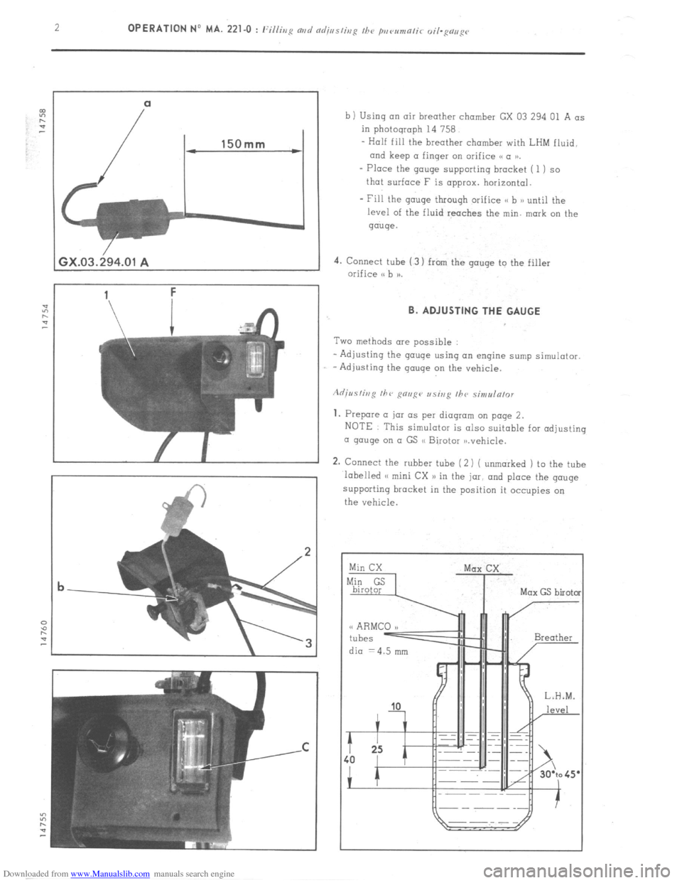
b ) Using an air breather chamber GX 03 294 01 A as
in photograph 14 758.
- Half fill the breather chamber with LHM fluid.
and keep (I finger on orifice (S a tn.
- Place the gouge supporting bracket ( 1) so
that surface F is approx. horizontal.
- Fill the gauge through orifice <( b n until the
level of the fluid reaches the min. mark on the
gauge.
4. Connect tube (3) from the gouge to the filler
orifice I. B. ADJUSTING THE GAUGE
Two methods ore possible
- Adjusting the gouge using an engine sump simulator.
-Adjusting the gauge on the vehicle.
1. Prepare (I jar as per diagram on page 2.
NOTE This simulator is also suitable for adjusting
a gouge on o GS (S Birotor ,n.vehicle.
2. Connect the rubber tube (2 i ( unmarked 1 to the tube
labelled (< mini CX n in the jar, and place the gouge
supporting bracket in the position it occupies on
the vehicle.
dia =4.5 mm
Page 187 of 394

Downloaded from www.Manualslib.com manuals search engine OPERATION No MA. 320-00 : (.l~n~~/(-/(,~iz/i(-c m/d s/we-in: ~o~///,w. o/ //I<, /r,t~///c cc,,,, or/r r Op. MA. 32Oz.00 3
III. OPERATIONAL DIAGRAM OF TORQUE CONVERTER
Engine running, gear-lever in neutral
Page 212 of 394
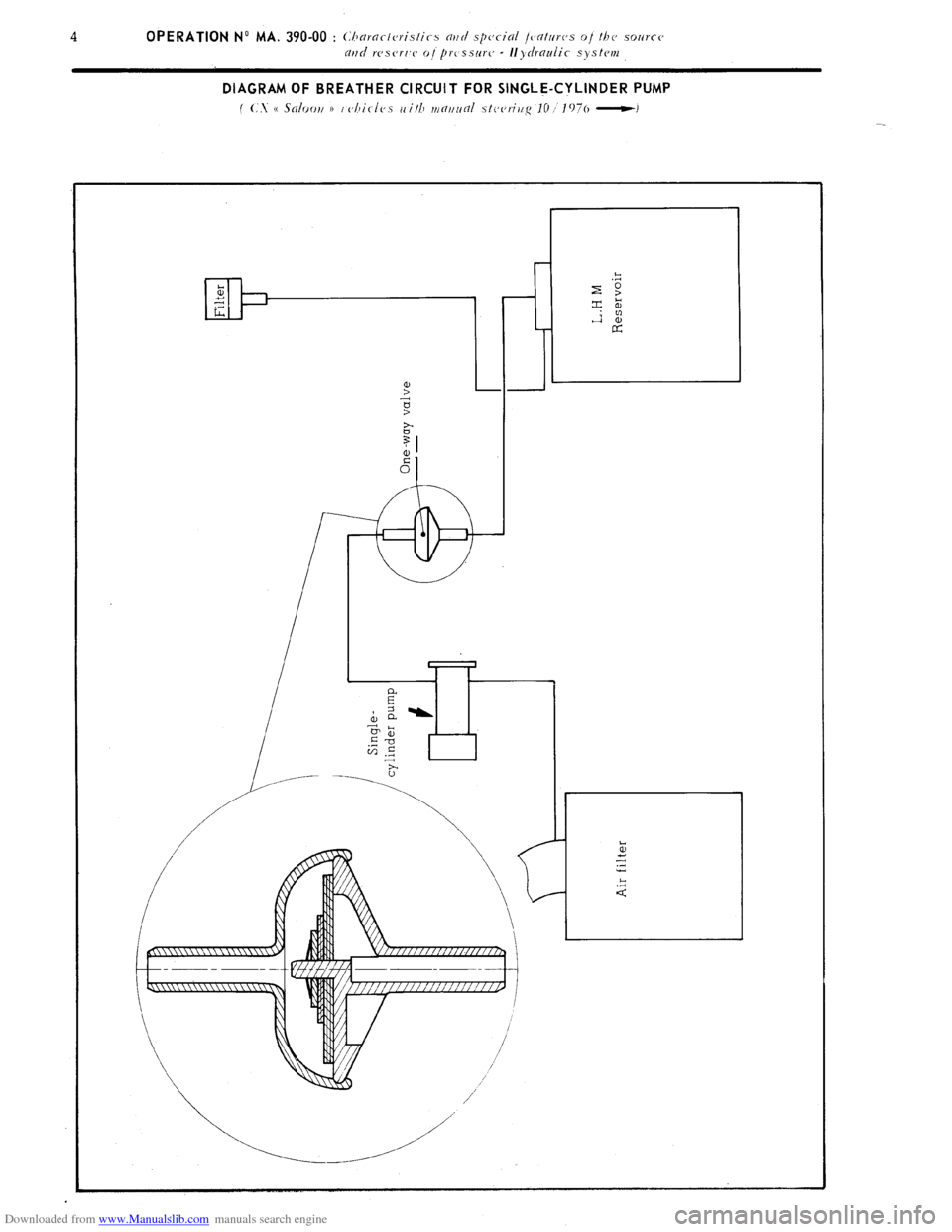
Downloaded from www.Manualslib.com manuals search engine DIAGRAM OF BREATHER CIRCUIT FOR SINGLE-CYLINDER PUMP
f (:. e Saloori 1) i cjhirles with mf7~7~inl stcjeriiig IO I 1976 -1
Page 215 of 394

Downloaded from www.Manualslib.com manuals search engine Op. MA. 390.00 i
DIAGRAMS OF OPERATION
CUT-OUT
1 a hydou ic CI~CIII!
f
Page 218 of 394
Downloaded from www.Manualslib.com manuals search engine 10 OPERATION No MA. 390-00 : Churarteristics and special features oi the source
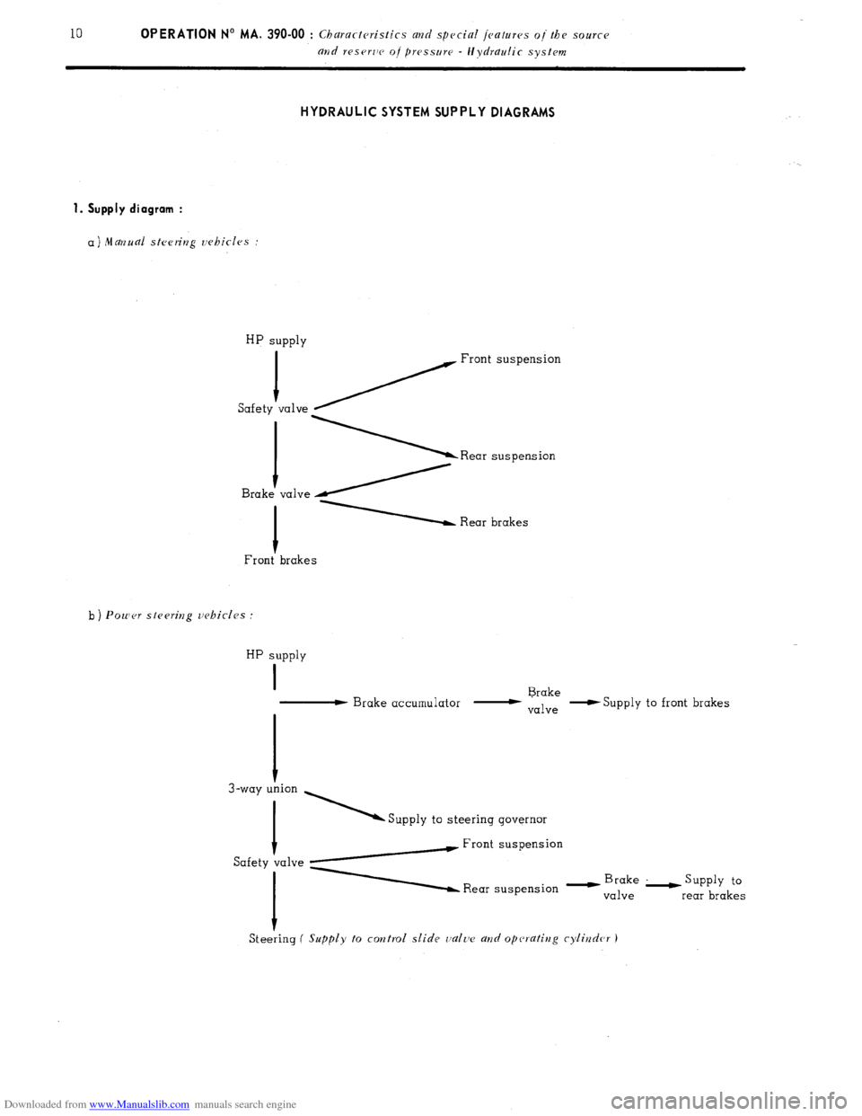
and reserlv oj pressure - Hydraulic system HYDRAULIC SYSTEM SUPPLY DIAGRAMS
1. Supply diagram :
a) Manual steering vehicles :
HP supply
1
Safety ~ Front suspension
va1ve \Rear suspension valve /
1 Rear brakes
Front’ brakes
b ) Power stesritzg vehicles :
HP supply
I
- Brake accumulator - Brake
valve -S
upply to front brakes
I
3-way T ’ Supply to steering governor
Safety talve yw Front suspension
A Rear suspension - y”,;“,“,’ L supp1y to
rear brakes
Steeiing
( Supply to control slide valtv a?zd operating cylirzder J
Page 219 of 394
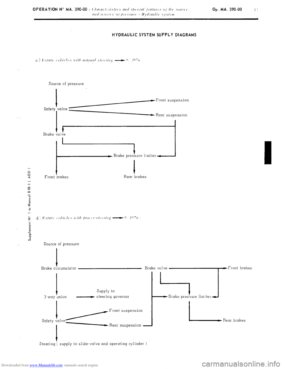
Downloaded from www.Manualslib.com manuals search engine HYDRAULIC SYSTEM SUP.PLY DIAGRAMS
Source of pressure
I
h-Front suspension
Safety “‘lve ; Rear suspension
I
I Brake valve
i :ure limiter-
1
Front brakes Rear brakes
Source of pressure
I
Brake cccumulator
Supply to
I-way wion - steering governor
/Front
Safety va1ve- Rear suspension
I
Steering ( supply to slide-valve and operating cylinder )
Page 221 of 394
![Citroen CX 1977 1.G Owners Manual Downloaded from www.Manualslib.com manuals search engine OPERATION No MA. 390-00 : (.hnrncteristics a?zd special fc~atuws oj the SOIUCC
arld ~~~scrm~ o]~prc’ss~~rc - Hydraulic systrm
2. Aisembly d Citroen CX 1977 1.G Owners Manual Downloaded from www.Manualslib.com manuals search engine OPERATION No MA. 390-00 : (.hnrncteristics a?zd special fc~atuws oj the SOIUCC
arld ~~~scrm~ o]~prc’ss~~rc - Hydraulic systrm
2. Aisembly d](/img/9/4131/w960_4131-220.png)
Downloaded from www.Manualslib.com manuals search engine OPERATION No MA. 390-00 : (.hnrncteristics a?zd special fc~atuws oj the SOIUCC
arld ~~~scrm~ o]~prc’ss~~rc - Hydraulic systrm
2. Aisembly diagram : Op. MA. 390-00 13
Page 254 of 394

Downloaded from www.Manualslib.com manuals search engine OPERATION No MA. 430-00 : (lsnmr/eris/irs nvrl .s/jrrinl /c,n/uws 0, /he susfiv,,sias Op. MA. 430-00 3
MANUAL HEIGHT CONTROL
‘hi anual height control quadrant :
I. High position
II. Intermediate high position
III. Normal driving position
IV Low position
G Assembly diagram for manual height control
:
L.43.2
Seen along Fl
Page 288 of 394
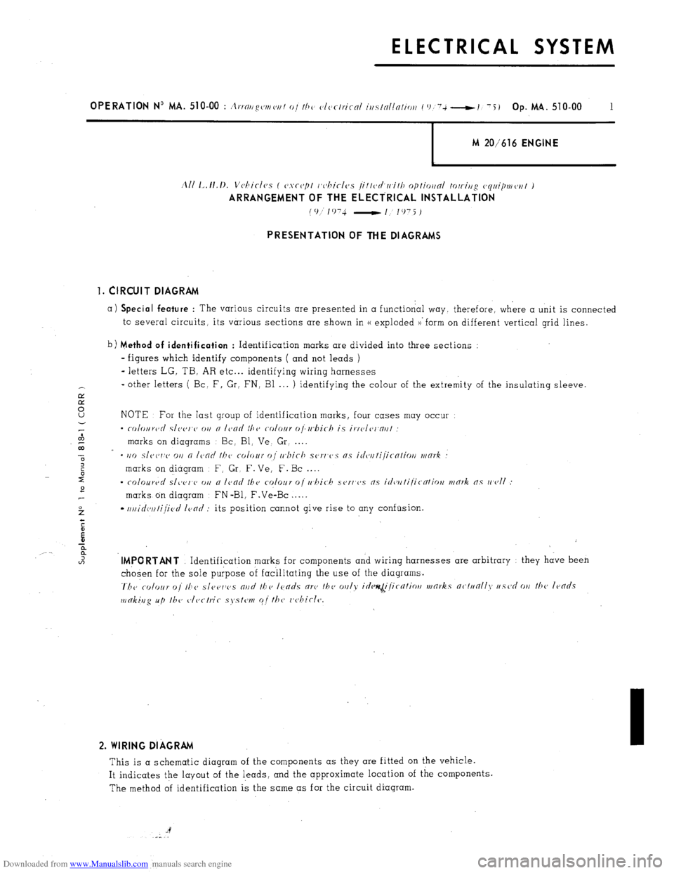
Downloaded from www.Manualslib.com manuals search engine ELECTRICAL SYSTEM
M 20/616 ENGINE
PRESENTATION OF THE DIAGRAMS
1. CIRCUIT DIAGRAM
a) Special feature
: The various circuits are presented in a functional way. therefore, where a unit is connected
to several circuits, its various sections are shown in (( exploded ~‘form on different vertical grid lines. b) Method of identification
: Identification marks are divided into three sections :
- figures which identify components ( and not leads )
- letters LG. TB. AR etc... identifying wiring harnesses
_
other letters ( Bc. F, Gr, FN, Bl . . . ) identifying the colour of the extremity of the insulating sleeve.
NOTE For the Iast group of identification marks, four cases may occur
- coloiirc~rl slc,c,f,c~ 01l 0 Ic’cirf tllc, colour of wbic-h is irrc’l~~r.nrlI
marks on diagrams Bc, Bl, Ve. Gr. . . . .
= l/o s/oc,r,c, 01) 0 I~~ocl //Ic, c-olour of whit11 .ser1’c’s ns icfc~rltijicntiot, work
marks on diagram F, Gr, F. Ve, E. Bc . . . .
- colourc~ri .s/t,c~c~c, O,I n Icncl the colour uj rrhich SCJ~,‘C’.T ns ic/cvrtijitntiorL mnrk 0.5 rr~ol/ :
marks on diagram : FN -Bl, F.Ve-Bc . . . . .
-
trr/id~~~~li~~c~d I~>nd : its position cannot give rise to any confusion. .lMPORTANT
Identification marks for components and wiring harnesses are arbitrary they have been
chosen for the sole purpose of facilitating the use of the diagrams.
‘1.17~~ colour 01’ II,c~ sl~~c~~~c~s n~ld the I~~atls ore the rnr~ly id~~~~i,/t’cntiot~ vrork,s nc-/uoll\, uscjd OII tlj~~ I~~ncls
making up /h(, cllectric s~~stern c;/ the l,c~hir-Ie. 2. WIRING DIAGRAM
This is a schematic diagram of the components as they are fitted on the vehicle.
It indicates the layout of the leads, and the approximate location of the components.
The method of identification is the same as for the circuit diagram.
Page 289 of 394
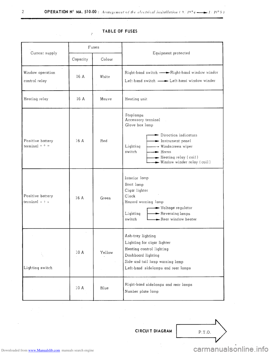
Downloaded from www.Manualslib.com manuals search engine TABLE OF FUSES
Current supply
findow operation
ontrol relay Fuses
Equipment protected
Capacity Colour
Right-hand switch -Right-hand window winder
16 A White
Left-hand switch - Left-hand window winder
Ieating relay 16 A Mauve Heating unit
Stoplamps
Accessory terminal
Glove box lamp
‘ositive battery
erminal (( + )). 16
A Red Direction indicators
E Instrument panel
Lighting -- Windscreen wiper
switch Horns
Heating relay ( coil )
Window winder relay ( coil )
‘ositive battery
erminal (( t 1) 16 A Green Interior lamp
Boot lamp
Cigar lighter
Clock
Hazard warning lamp
Lighting
switch
E
Voltage’ regulator
Reversing lamps
Rear window heater
Ash-tray lighting
10 A Yellow Lighting for cigar lighter
Heating control lighting
Dashboard lighting
,ighting switch Side- and tail lamp warning lamp
Left-hand sidelamps and rear lamps
10 A Blue Right-hand sidelamps and rear lamps
Number plate lamp Cl RCUI T DIAGRAM
r>