compression ratio Citroen CX 1977 1.G Workshop Manual
[x] Cancel search | Manufacturer: CITROEN, Model Year: 1977, Model line: CX, Model: Citroen CX 1977 1.GPages: 394
Page 52 of 394
Downloaded from www.Manualslib.com manuals search engine I. CHARACTERISTICS
:
0
u
5 Cooling system : Water cooled.
z
T cx 2000 cx 2200 CX 2400 and Prestige
CX 2400 GTI
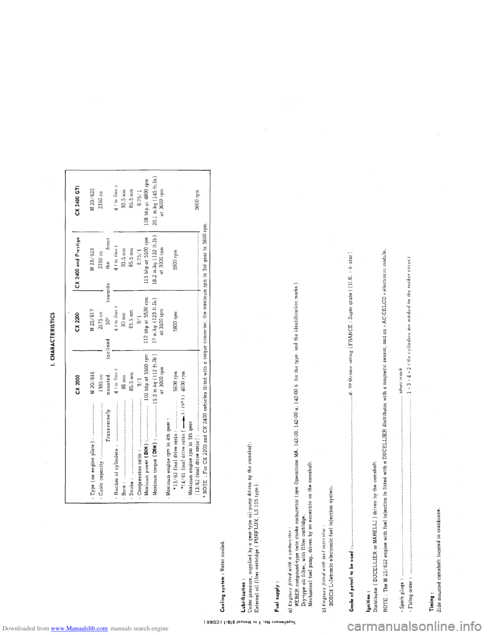
- Type ( on engine p’late ) : _..._................... M 20/616 M 22/617 M 23/ 623
M 23/622
Cubic capacity : . . .._......_...............
1985 cc 2175 cc 2350 cc 2350 cc
Transversely mounted, inclined
300 towards the front
Number of cylinders : _........................... 4 (iI/ linr, J 4 Iin linr,)
4 (irr /iUP J 4 f in lin i’ ,
Bore : 86 mm 90 mm 93.5 mm 93.5 mm
- Stroke : .,.,,_,.,.,....____.,.. .._._.....................
85.5 mm 85.5 mm 85.5 mm
85.5 mm
Compression ratio :
9/I 9/l 8.7511 8.7511
Maximum power ( DIN ) : . . . .._................... 102 bhp at 5500 rpm 112 bhp at 5500 rpm 115 bhp ot 5500 rpm
128 bhp at 4800 rpm
Maximum torque (DIN)
: . . 15.5 m.kg (112 ft.Ib ) 17 m.kq (123 ft.Ib) 18.2 m.kg ( 132 ft.Ib)
20.1 mkq (145 ft.Ib)
at 3000 rpm at 3500 rpm at 3000 rpm
at 3600 rpm
Maximum engine rpm in 4th gear :
* 13/62 final drive rtrtio :
5600 rpm 5800 rpm 5900 rpm
*14/61 final drive ratio ( -1 1’175 J 4600 rpm
Maximum engine rpm in 5th gear
(
13,‘62 final drive ratio ) : ,._............,..,........,....,.,........,..,.,..... .._.........,................ .._..._...................
5600 rpm
* NOTE : For CX 2200 and CX 2400 vehicles fitted with a torque converter, the maximum rpm in 3rd gear is 5600 rpm.
: Lubrification :
i
Under pressure, supplied by o gear-type oil-pump driven by the camshaft.
2
External oil filter cartridge ( PURFLUX, LS 105 type ).
d
z
;
i Fuel supply :
a
i a) Engines fitted u~ifh a rnrbuwffor
WEBER compound-type twin choke carburettor (s.ee Operations MA. 142-00, 142-00 a, 142-00 b far the type, and the identification marks )
Dry-type air filter, with filter cartridge.
Mechanical fuel pump, driven by on eccentric on the camshaft.
b) i?ugi,jes ji/f.rd II ith /LIP/ iniPr/ioo :
BOSCH L-Jetronic electronic fuel injection system
Grade of pet,ol to be used : > ._,,,,.,_.._,,,,,.,......... . .._...o....._............................................. K.
99 Orrani ralrrig (FRANCE : Super grade ) (U.K. : 4-star )
Ignition :
Distributor ( DUCELLIER or MARELLI ) driven by the camshaft.
NOTE : The M 23/622 engine with fuel injection is fitted with (I DUCELLIER distributor with a magnetic sensor, and an u AC-DELCO /a electronic module.
- Spark pluqs : .................................................................................................................................... shorf warh
Firing o&r : .................................................................................................................................... 1 - 3 - 4 - 2 f tbu cylinders ale INR&Cd 011 the roc6w COI rr,
Timing :
Side mounted camshaft located in crankcase.
Page 60 of 394
Downloaded from www.Manualslib.com manuals search engine OPERATION N” MA. 100-00 : (:hnractc,ri.stics arid specinl j(,atrlres o,/ the> cl,gi?lcJ. Op. MA. 100-00 1
9
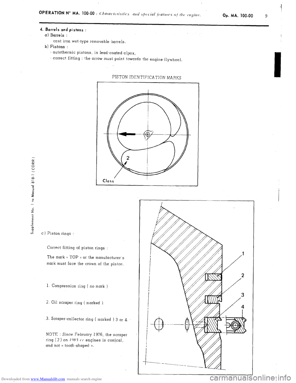
4. Barrels and pistons :
a)
Barrels :
cast iron wet-type removable barrels.
b) Pistons :
-- autothermic pistons, in lead-coated alpax,
- correct fitting : the arrow must point towards the engine flywheel
7
co
m
C ) Piston rings : PISTON IDENTIFICATION MARKS
Correct fitting of piston rings :
The mark (( TOP 1) or the manufacturer’s
mark must face the crown of the piston.
1. Compression ring ( no mark )
2. Oil scraper ring ( marked )
3. Scraper-collector ring ( marked ) 3 or 4
NOTE : Since February 1976, the scraper
ring (2 ) on I a85 cc engines is conical,
and not (( tooth-shaped )).
Page 159 of 394
Downloaded from www.Manualslib.com manuals search engine 4 OPERATION No MA. 210-O : (hcrkir,p or,
III. FITTING THE DISTRIBUTOR ONTO THE VEHICLE
1. Set the distributor to the static
advance point :
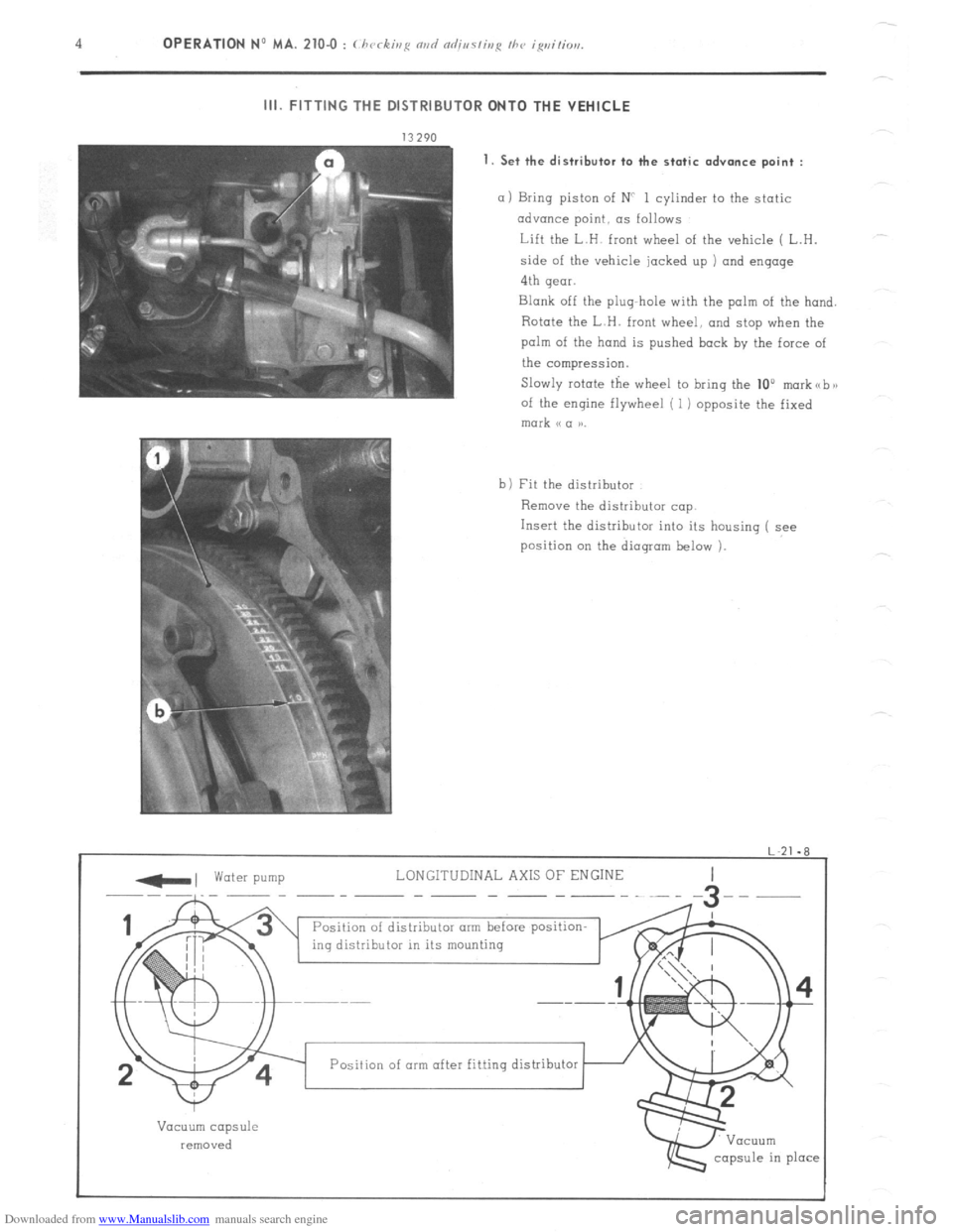
a 1 Bring piston of NC 1 cylinder to the static
advance point, as follows
Lift the L.H. front wheel of the vehicle ( L.H.
side of the vehicle jacked up ) and engage
4th gear.
Blank off the plug-hole with the palm of the hand.
Rotate the L.H. front wheel, and stop when the
palm of the hand is pushed back by the force of
the compression.
Slowly rotate the wheel to bring the 10”
morkabx
of the engine flywheel ( 1) opposite the fixed mark (c a aa.
b) Fit the distributor
Remove the distributor cap.
Insert the distributor into its housing ( see
position on the dioqram below 1.
-, water pump LONGITUDINAL AXIS OF ENGINE
--~-__ -- -- ----~--
Position of distributor arm before position-
ing distributor in its mounting
I
w
Vacuum capsule
removed
capsule in place Position of arm after fitting distributor
Page 164 of 394
Downloaded from www.Manualslib.com manuals search engine 4 OPERATION No MA. 210-O o : (./wrkh,i: rind nrlj,,s/inp /hc rlvr/,riai< igvi,io,, ~YS/C,,,,.
II;. FITTING THE DISTRIBUTOR ONTO THE VEHICLE
_ water pump
LONGITUDI 1 AL AXlS OF ENGINE
.-.-.-
distributor arm
Position of dist:ibutor arm befol
fitting distributor in its mountin 1. Set the distributor to the static advance curve :
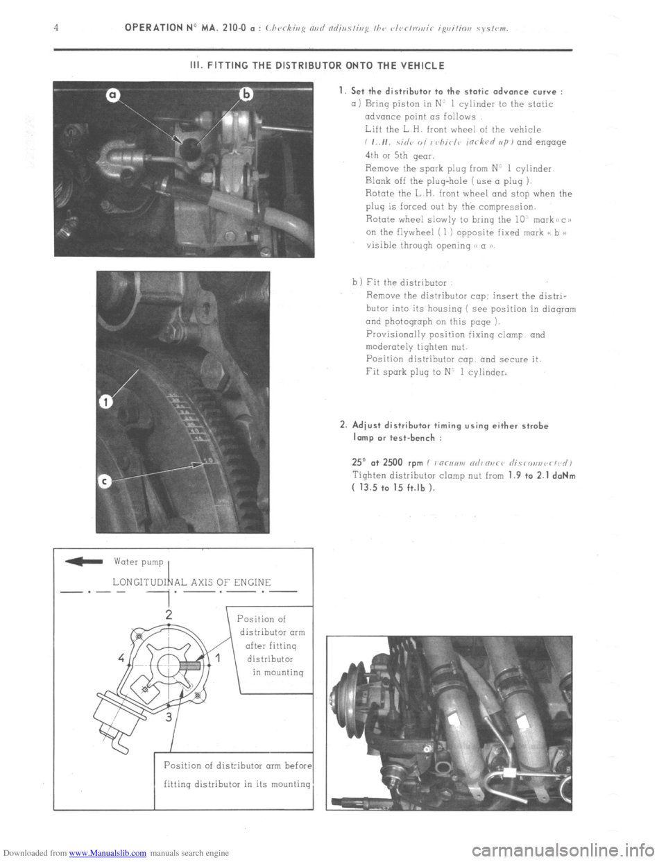
a) Bring piston in N’ 1 cylinder to the static
advance point LTS follows
Lift the L H. front wheel of the vehicle
i ,..I,. .\;,I<~ o, / vhirl<~ in< kvd ,,/I, and engage
4th or 5th qeor.
Remove the spark plug from N’ 1 cylinder
Blank off the plug-hole (use a plug ).
Rotate the L H. front wheel and stop when the
plug is forced out by the compression.
Rotate wheel slowly to bring the 10, markiicai
on the flywheel ( 1 ) opposite fixed mark cs b >)
visible throuqh opening S< a ))
b 1 Fit the distributor
Remove the distributor cop: insert the distri-
butor into its housing ( see position in dioqrom
and photograph on this page ).
Provisionally position fixing clamp and
moderately tighten nut.
Position distributor cap and secure it.
Fit spark plug to N’ 1 cylinder. 2. Adiust distributor timing using either strobe
lamp or test-bench :
25” .a+ 2500 rpm I 7 “c,,,m nrli n,,ci’ rlicronsvr~d)
Tiqhten distributor clomp nut from 1.9 +o 2.1 daNm
( 13.5 to 15 ft.lb ).
Page 384 of 394
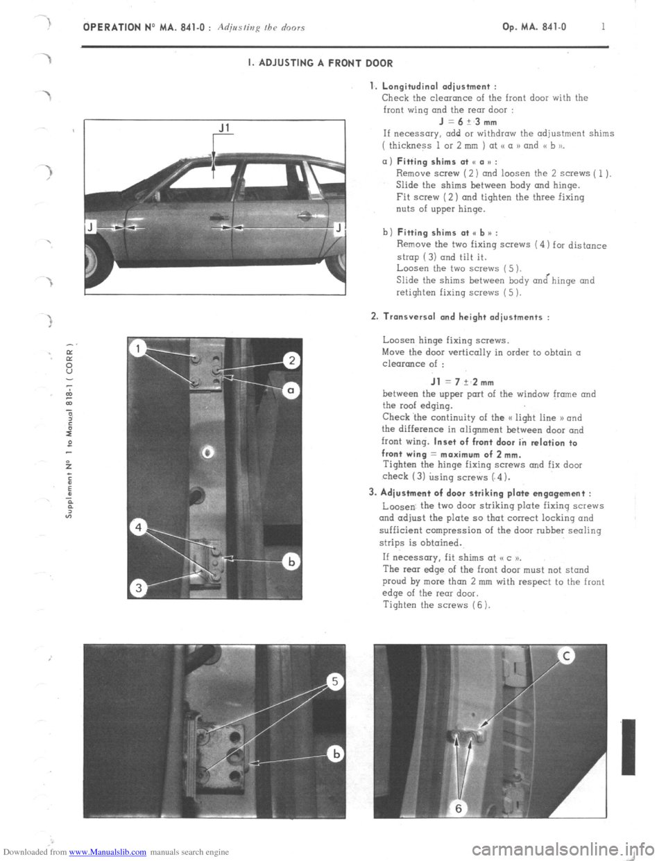
Downloaded from www.Manualslib.com manuals search engine OPERATION No MA. 841-O : Adjusting fh~ doors Op. MA. 841-O 1 I. ADJUSTING A FRONT DOOR
1. Longitudinal adiustment :
Check
the clearance of the front door with the
front wing and the rear door : J=6+_3mm
If necessary. add or withdraw the adjustment shims
( thickness 1 or 2 mm ) at <( a 1) and << b to_ a) Fitting shims at SC a u :
Remove screw (2) and loosen the 2 screws ( 1).
Slide the shims between hody and hinge.
Fit screw (2) and tighten the three fixing
nuts of upper hinge.
b) Fitting shims at <, b n :
Remove the two fixing screws (4) for distance
strop (3) and tilt it.
Loosen the two screws (5 ).
Slide the shims between body &hinge and
retighten fixing screws (5 ). 2. Transversal and height adjustments :
Loosen hinge fixing screws.
Move the door vertically in order to obtain a
clearance of : Jl = 7 +‘2mm
between the upper port of the window frame and
the roof edging.
Check ‘the continuity of the a light line 1) and
the difference in alignment between door and
front wing. Inset of front door in relation to
front wing = maximum of 2 mm.
Tighten the hinge fixing SCWNS and fix door
check (3) using screws (“4). 3. Adjustment of door striking plate engagement :
Loosen. the two door striking plate fixing screws
and adjust the plate so that correct locking and
sufficient compression of the door rubber sealing
strips is obtained.
If necessary, fit shims at (cc )P.
The rear edge of the front door must not stand
proud by more than 2 mm with respect to the front
edge of the rear door.
Tighten the screws (6 ).
Page 385 of 394
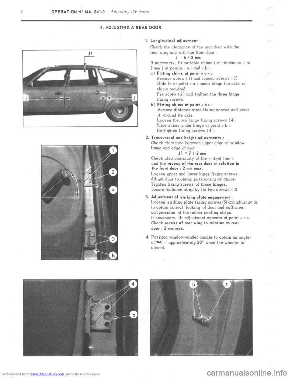
Downloaded from www.Manualslib.com manuals search engine 2 OPERATION NO MA. 841-O : Adjmfing /he o’r,ors
II. ADJUSTING A REAR DOOR
1. Longitudinal adjustment :
Check the clearonce of the rear door with the
rear wing and with the front door :
J =6+~3mm
If necessary, fit Suitable shims ( of thickness 1 or
2 mm ) at points (( a N and (( b )).
a) Fitting shims at point II a * :
Remove screw ( 1) ond loosen screws (2).
Slide in at point I< a D under hinge the shim or
shims required.
Fix scr&v (2 ).and tighten the three hinge
fixing screws.
b)
Fitting shims at point e b u :
Remove distance strop fixing screws and pivot
it, around its axis.
Loosen the two hinge fixing screws (4).
Slide shims under hinge at point <, b >j.
Re-tighten fixing screws (4 1.
2. Transversal and height adjustments :
Check clearance between upper edge of window
frmne and
edqe of roof :
Jl =7+~2mm
Check also continuity of the G light line x
and the recess
of the rear door in relation ta
the front door : 2 mm max.
Loosen upper and lower hinge fixing screws.
Adjust door to obtain positioning (IS above.
Tighten fixing screws of these hinges.
Secure distance strap by its two screws (3)
3. Adjustment of striking plate engagement :
Loosen striking plate fixing screws (3) and adjust so as
to obtain correct locking of door and sufficient
compression of the rubber sealing strips.
If necessary, fit adjustment spacers at point o c u.
Check recess
of rear wing in relation ta rear
dwr : 2 mm max.
4: Position window-winder handle to obtain an angle.
of W = approximately 30’ when the window is
closed.