Alignment Citroen CX 1981 1.G User Guide
[x] Cancel search | Manufacturer: CITROEN, Model Year: 1981, Model line: CX, Model: Citroen CX 1981 1.GPages: 394
Page 250 of 394
Downloaded from www.Manualslib.com manuals search engine Op. MA. 420.0 1
CHECKING THE REAR AXLE USING OPTICAL EQUIPMENT
NOTE For detailed instructions on the use of optical equipment see front axle checking operation (Op. MA. 410-O)
1. Checking’axle alignment :
L
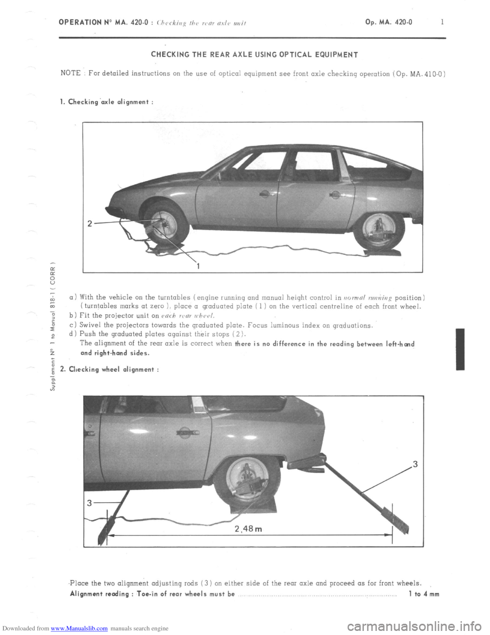
(11 With the vehicle on the turntables (engine running and manual height control in normnl runniup position)
& ( turntables marks at zero 1, place a graduated plate ( 1 i on the vertical centreline of each front wheel.
-6
: b) Fit the projector unit on ca<-h rcnl uhccl.
I”
c i Swivel the projectors towards the graduated plate. Focus luminous index on graduations.
2 d ) Push the graduated plates against their stops ( 2 ).
The alignment of the
rear axle is correct when there is no difference in the reading between left-hcnd
52 and right-hand sides.
;
i 2. Checking wheel alignment :
n
2
“7
,Ploce the two aliqnmeht adjusting rods (3 ) on either side of the rear axle and proceed as for front wheels.
Alignment reading : Toe-in of rear wheels must be 1 to4mm
Page 262 of 394
Downloaded from www.Manualslib.com manuals search engine STEERING COLUMN ( ‘11’ l’)‘o -1
L.44-21
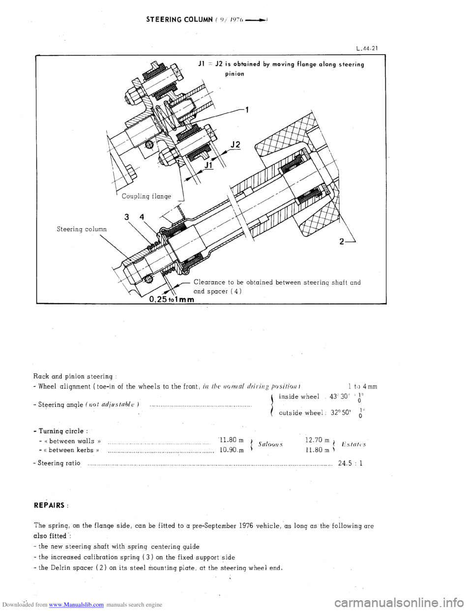
Jl = J2 is obtuined by moving flange along steering
pinion
Steering co1
Clearance to be obtained between steering shaft and
mind spacer (4)
1 a
Rack and pinion steering :
- Wheel alignment ( toe-in of the wheels to the front, i/z, /bc~ rtot~/nl rlrir,ir/g posifiort I 1 tk) 4 mm
inside wheel 43’30’
1”
- Steering angle (Ilot djustahlc~ ) 0
outside wheel : 32’50’ i’
- Turning circle :
- CC between walls )) Il.80 m
I Snloo~2 s 12.70 m
.
(! Estntc’s
- CC between kerbs )I
. . . . . ..__.._........................................,.,.. 10.90.m 11.80 m
- Steering ratio, .-.......................-............................................................................................................ 24.5 : 1
REPAIRS :
The spring, on the flange side, can be fitted to a preSeptember 1976 vehicle,‘as long as the following are
also fitted -:
- the new steering shaft with spring centerinq guide
- the increased calibration spring ( 3 ) on the fixed support side
- the Delrin spacer (2) on its steel mounting plate. at the steering wheel end.
Page 263 of 394
Downloaded from www.Manualslib.com manuals search engine ll, SPECIAL FEATURES
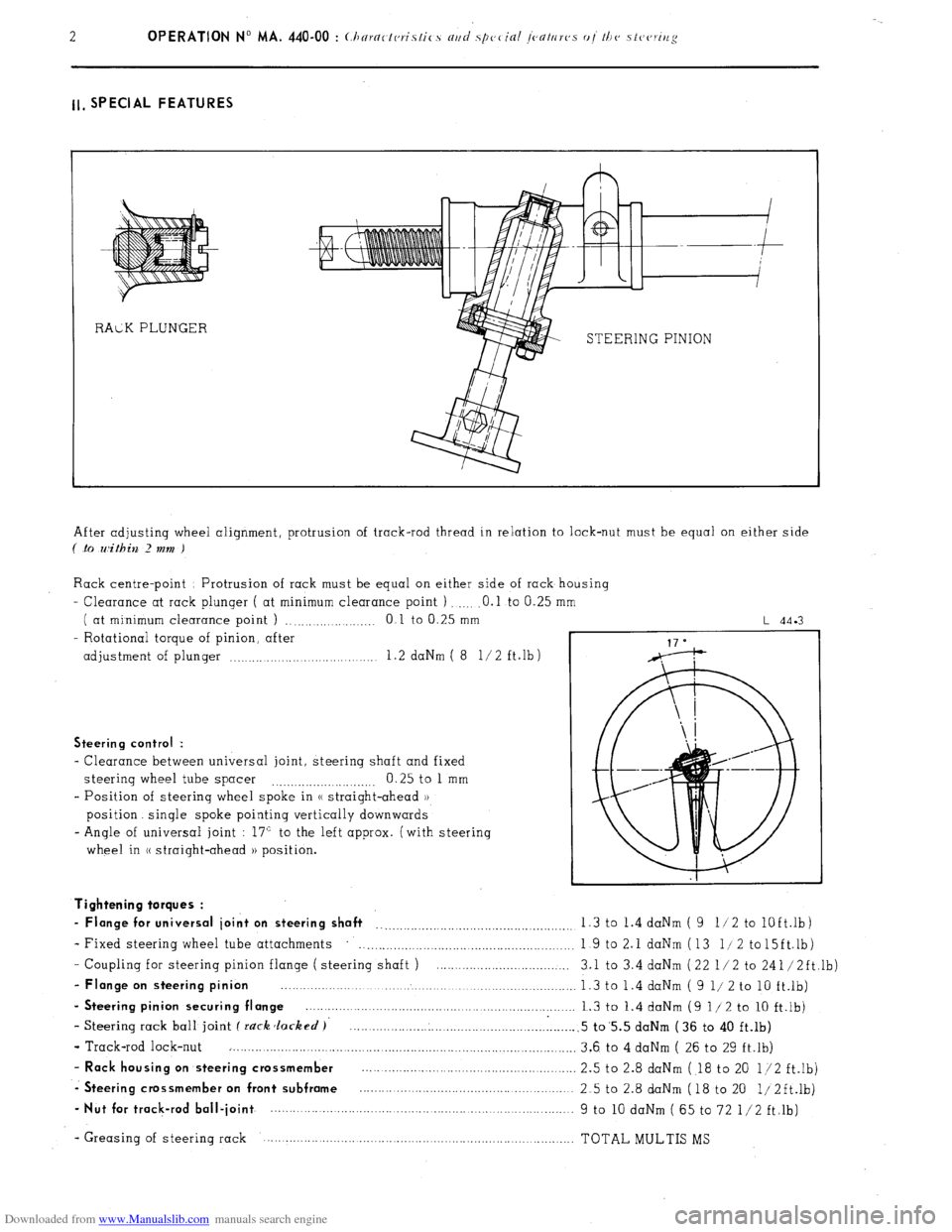
STEERING PINION
After adjusting wheel alignment, protrusion of track-rod thread in relation to lock-nut must be equal on either side
( .to within 2 mm )
Rack centre-point Protrusion of rack must be equal on either side of rack housing
- Clearance at rack plunger ( at minimum clearance point ) .O.l to 0.25
( at minimum clearance point ) ., .,...._...... .._._ 0 1 to 0.25 mm
- Rotational torque of pinion, after
adjustment of plunger .._..... .._.... 1.2 daNm ( 8 l/2 ft.lb)
L 44.3
Steering control :
- Clearance between universal joint, steering shaft and fixed
steering wheel tube spacer 0.25 to 1 mm
.._....__._..._.... ._..__..
- Position of steering wheel spoke in (( straight-ahead ))
position. single spoke pointing vertically downwards
- Angle of universal joint : 17” to the left approx. (with steering
wheel in (( straight-ahead )) position.
- Coupling for steering pinion flange ( steering shaft ) ....................................
- Flange on steering pinion ................................................................................
- Steering pinion securing flange ........................................................................
- Steering rack ball joint f rack Jacked )’ .............................................................
- Track-rod lock-nut ..............................................................................................
- Rack housing on steering crossmember ..........................................................
-. Steering crossmember on front subframe ..........................................................
- Nut for track-rod ball-joint ................. ................................... ..... ...................... Tightening torques :
- Flange for universal joint on steering shaft __..._.__.._._.........,.........................,. 1.3 to 1.4 daNm ( 9 11 2 to
lOft.lb)
- Fixed steering wheel tube attachments
. . . . . . . . . . . . . . . . . . . . . 1 9 to 2.1 daNm (13 l/2 to15ft.lb)
3.1 to 3.4 daNm (22 l/2 to 241/2ft,lb)
1.3 to 1.4 daNm ( 9 l/ 2 to 10 ft.lb)
1.3 to 1.4 daNm (9 l/2 to 10 ft.lb)
.5 to’5.5 daNm (36 to 40 ft.lb)
3.6 to 4 daNm ( 26 to 29 ft.lb)
2.5 to 2.8 daNm ( 18 to 20 l/2 ft.lb)
2.5 to 2.8 daNm (18 to 20 1/2ft.lb)
9 to 10 daNm ( 65 to 72 l/2 ft.lb)
- Greasing of steering rack TOTAL MULTIS MS
Page 264 of 394
Downloaded from www.Manualslib.com manuals search engine II. POWER STEERING WITH POWERED RETURN
I. CHARACTERISTICS
Hydraulically operated rack and pinion steering Steering
ratio . . . . . . . . . . . . . . . . . . . . . . . . . . . . . . . . . . . . . . . . . . . . . . . . . . . . . . . . . . . . . . . . . . . . . . . . . . . . . . . . . . . . . . . . . . . . . . . . . . . . . . . . . . . . . . . . . . . . . . . . .. 13 5 i
- No of steering wheel turns from lock to lock
. . . . . . . .._._.__................................................ 25
- Turning circle (( between walls ))
11 80m
(.S x00 OIlCi ( s .2x0 solooll.~
(( between kerbs )) 10 90 m t
/( between walls )) 12 70 m
I( between kerbs 1) 11 80 m t I’\/N/l’ N/id I’n~\lix”
- Wheel alignment ( toe-in of wheels to the front i (i/l //I( //r~rjj/rll c/r;/ ii/:: p, cilirJ/i 1 1 to 4 mm
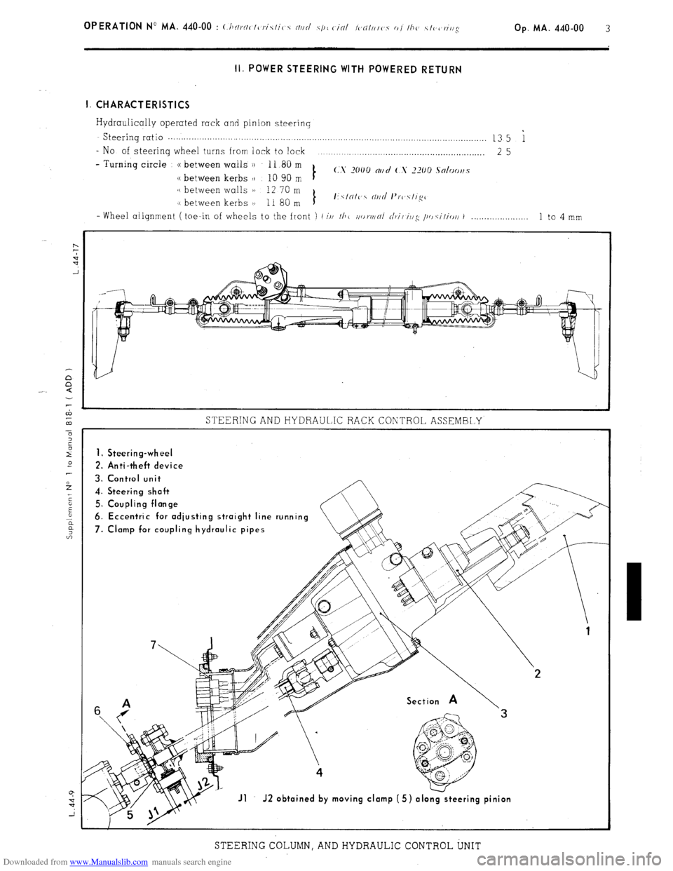
STEERING AND HYDRAULIC RACK CONTROL ASSEMBLY
1. Steering-wheel
2. Anti-theft device
3. Control unit
4. Steering shoft
5. Coupling flonge
6. Eccentric for odjusting stroight line running
7. Clomp for coupling hydraulic pipes
Jl J2 obtoined by moving clomp (5) olo
STEERING COLUMN, AND HYDRAULIC CONTROL UNIT
Page 272 of 394
Downloaded from www.Manualslib.com manuals search engine Op. MA. 440.00 11
2. SPECIAL FEATURES
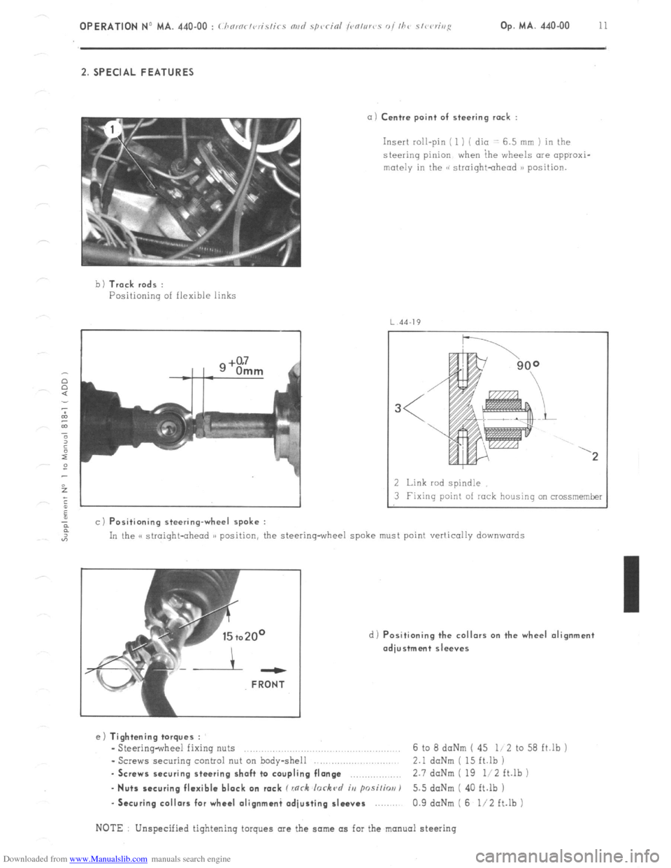
a) Centre point of steering rack :
Insert roll-pin ( 1 ) ( dio -: 6.5 mm ) in the
steering pinion when ihe wheels are appraxi-
mutely in the GG siroightohead )B position.
b 1 Track rods :
Positioning of flexible links
4J
a c) Positioning steering-wheel spoke :
2 Link rod spindle
3 Fixing point of rock housing on crossmemker
In the C( straight-ahead )) position, the steering-wheel spoke must point vertically
downwards
d) Positioning the collars on the wheel alignment
adjustment sleeves ---
FRONT
e) Tightening torques :
- Steering-wheel fixing nuts ..,.,........,......,.. .., 6 to 8 daNm ( 45 li 2 to 58 ft.lb j
- Screws securing control nut on body-shell 2.1 daNm ( 15 ft.lb )
. Screws securing steering shaft to coupling flange ,.,,.,,,,,.,.,.,,, 2.7 doNm ( 19 li2 ft.lb )
- Nuts securing flexible block on rack C rnrh lorkc~d iu psi/h) 5.5 doNm ( 40 ft.lb )
-Securing collars for wheel olignmani adjusting sleeves 0.9 daNm ( 6 l/2 ft.lb )
NOTE Unspecified tightening torques are the same as for the manual steering
Page 348 of 394
Downloaded from www.Manualslib.com manuals search engine OP,ERATlON No MA. 530-00 : <.Ilnrnctc,rislics oj I/IV cJlec/rical cor~~/~~r~c~~t/s. Op. MA. 530-00 1 I. ALTERNATORS - VOLTAGE REGULATORS
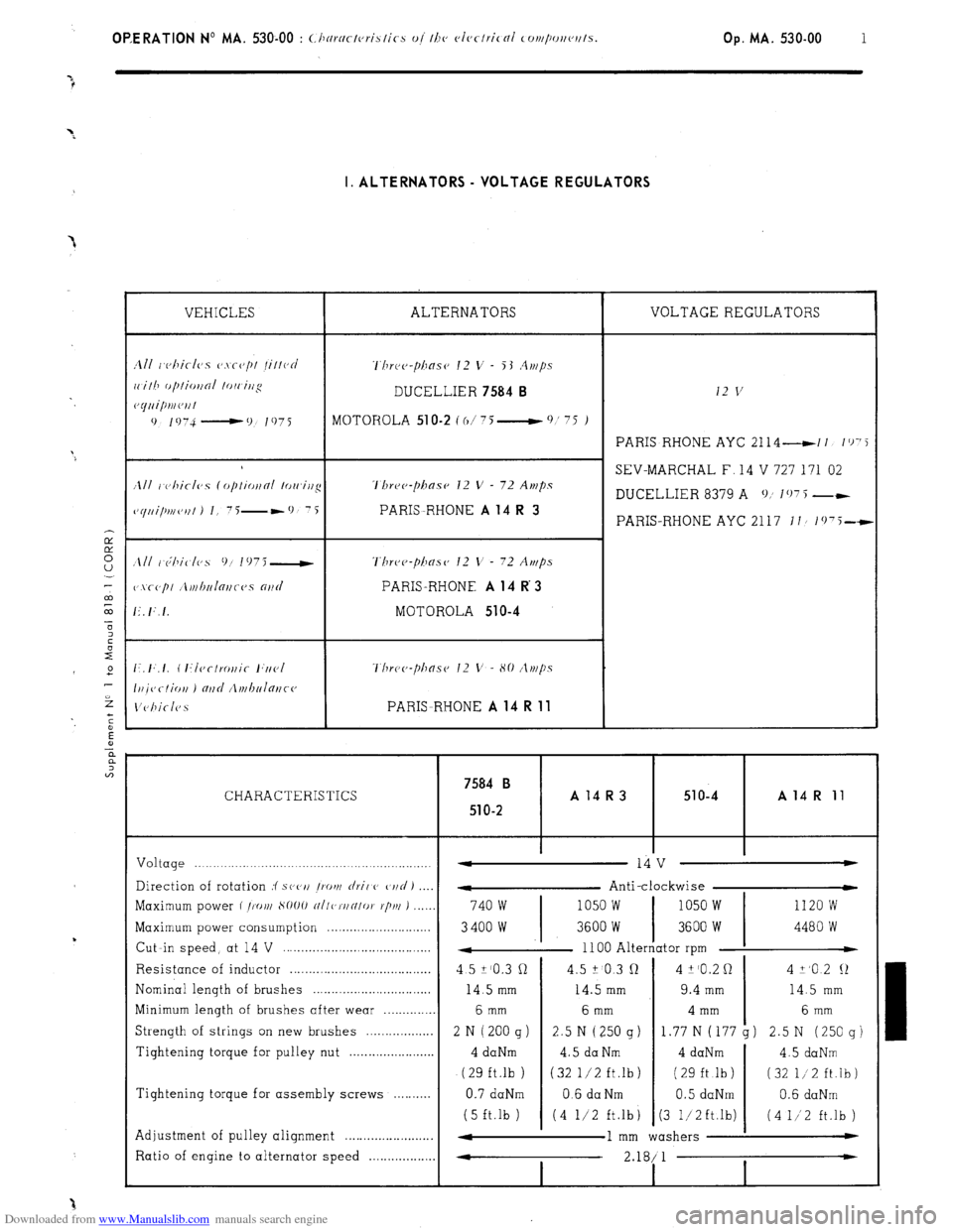
VEHICLES ALTERNATORS VOLTAGE REGULATORS
1111 r~c,hicl(~s CJ.\~(J/)/ /il/ocJ ‘l’hrc~c~-pilasc~ 12 v - 53 .4r,/ps
ri.ilh f~/~IioI~oI lo/i irjg DUCELLIER 7584 B 12 v c~yuipmc~ril
0 1 !, 74 - 0 I 97 i
MOTOHOLA 51 O-2 C o/ 75 __t 0 ’ ‘5 )
PARIS RHONE AYC 2114 -11 I’)‘5
SEV-MARCHAL F, 14 V 727 171 02
/Ill I c)hiclvs (opliotfni lowirtg ‘l’hre~~-phase 12 V - 72 Amps
DUCELLIER 8379 A 0; 107 5 --
~~yui/mc,,fl J I, 7i-*9 7i PARIS-RHONE A 14 R 3 PARIS-RHONE AYC 2117 II/ 1(j75-t
Three-phase’ 12 V - 72 Amps
PARIS-RHONE A 14 R 3
MOTOROLA 510-4
Thr~~~~-pha.s~~ 12 V - 80 /lt)t/?s
PARISRHONE A 14 R 11
7584 B CHARACTERISTICS A14R3 51 o-4 A 14 R 11
51
O-2
Voltage .._._._.._._.._____.......................,...................,. -
14 v w
Direction of rotation :f s(‘(‘I/ /rot)/
rlril C’ C,I/C/ J
- Anti-clockwise
Maximum power f /X),/I S1)OO
~/I/c,~/IN/oI. r/j/u ) ..,__, 740 w 1050 w 1050 w 1120 w
Maximum power consumption . . . . . .._..__.______........
3400 w 3600 W 3600 W 4480 W
Cut -in speed, at 14 V . .
4 1100 Alternator rpm t
Resistance of inductor . .
4 5 Z’O.3 cl 4.5 ? 0.3 Q 4 k’O.2 0 4 +,o 2 12
Nominal length of brushes .
14.5 mm 14.5 mm 9.4 mm 14.5 mm
Minimum length of brushes after wear . . 6 mm 6 mm 4 mm 6 mm
Strength of strings on new brushes . . . . . . . . . . . . . . . . . 2 N ( 200 g ) 2.5 N (250 g)
1.77 N (177 g) 2.5 N (250 g)
Tightening torque for pulley nut . . 4 daNm 4.5 da Nm 4 daNm
4.5 daNm
(29 ft.lb ) (32 l/2 ft.lb) ( 29 ft .lb ) (32 l/2 ft.lb)
Tightening torque for assembly screws .
0.7 daNm 0.6 da Nm 0.5 daNm 0.6 daNm
(5 ft.lb ) (4 l/2 ft.lb
j (3 1,‘2ft.lb) (4 1/‘2 ft.lb )
Adjustment of pulley alignment . . . . . . . . . . . . . . . . . . . . . . . . 4
1 mm washers w
Ratio of engine to alternator speed . . . 4
2.18/ 1 *
I I
Page 370 of 394
Downloaded from www.Manualslib.com manuals search engine Op. MA. 640-O 1 II CHECKING AND ADJUSTING :
1. Checking the operation of the air-conditioning :
Faulty operation may be due to the following
Insufficient quantity of R.12 fluid, caused by
improper filling 01 a leak.
Water in the system.
Insufficient quantity of fluid may be detected by examining the transparent index mark of the de-watering tank.
This lack of fluid would be shown up by the appearance of air-bubbles during operation.
The presence of water is shown up by the formation of a small quantity of ice near the pressure release valve
which causes irregular functioning of the system.
In both cases. the system must be drained. the circuits niust be put under vwzuum (to eliminate any trace of
water ). and refilled with R.12 fluid. 2. Corburation
: Adjusting the idling speeds (as soon as electric coolinq fans cut out )
a) Vc,hirlcs wi/hou/ loryue con wrtcr :
Engine idling speed 850 to 900 rpm ( compressor switched off )
Fast idling speed 1000 to 1050 rpm ( compressor in operation )
b) Vrhirles with torque co~twrt~~r
Engine idling speed 700 to 750 rpm ( compressor switched off )
Fast idling speed 725 to 775 rpm ( handbrake on, vehicle immobilised. one gear engaged, and compressor
switched off 1
The fast idling speed is adjustable by means of adjusting screw located on top of the vacuum capsule on the
cmburettor. NOTE
: In case the fast idle is impossible to obtain, the vacuum capsule may be moved ( slacken both fixing
screws on carburettor ). in order to reduce the clearance at the fixing point of the rod controlling the first
choke butterfly opening. 3. Adjusting the pulleys :
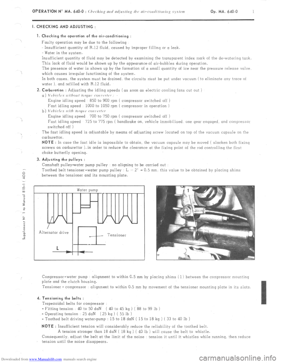
Camshaft pulley-water pump pulley no aligning to be carried out
Toothed belt tensioner-water pump pulley L = 2’ - 0.5 mm. this value to be obtained by placing shims
between the tensioner and its mounting plate. c
Water pump /
In
Alternator drive
Tensioner
Compressor-water pump alignment to within 0.5 mm by placing shims ( 1 ) between the compressor mounting
plo& and the clutch housing.
Tensioner -compressor alignment to within 0.5 mm by
movement of the tensioner mounting plate in its slots. 4. Tensioning the belts :
Trapezoidal belts for compressor :
- Fitting tension 40 to 50 daN ( 40 to 45 kg ) ( 88 to 99 lb )
- Operating tension 25 daN ( 25 kq ) ( 55 lb )
- Toothed belt driving water-pump : 15 to 18 doN ( 15 to 18 kg ) ( 33 to 40 Ib ) NOTE
: Insufficient tension will considerably reduce the reliability of the toothed belt.
A tension stronger than 18 daN ( 18 kg ) ( 40 lb ) will cause the belt to whistle.
Consequently, adjust the belt at the limit of the noise : tension it until it whistles while running. then reduce
tension until the noise disappears.
Page 384 of 394
Downloaded from www.Manualslib.com manuals search engine OPERATION No MA. 841-O : Adjusting fh~ doors Op. MA. 841-O 1 I. ADJUSTING A FRONT DOOR
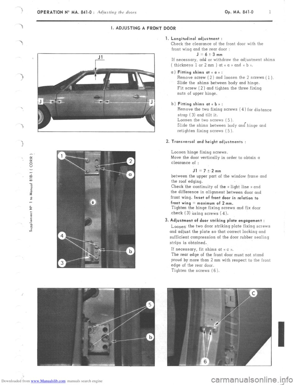
1. Longitudinal adiustment :
Check
the clearance of the front door with the
front wing and the rear door : J=6+_3mm
If necessary. add or withdraw the adjustment shims
( thickness 1 or 2 mm ) at <( a 1) and << b to_ a) Fitting shims at SC a u :
Remove screw (2) and loosen the 2 screws ( 1).
Slide the shims between hody and hinge.
Fit screw (2) and tighten the three fixing
nuts of upper hinge.
b) Fitting shims at <, b n :
Remove the two fixing screws (4) for distance
strop (3) and tilt it.
Loosen the two screws (5 ).
Slide the shims between body &hinge and
retighten fixing screws (5 ). 2. Transversal and height adjustments :
Loosen hinge fixing screws.
Move the door vertically in order to obtain a
clearance of : Jl = 7 +‘2mm
between the upper port of the window frame and
the roof edging.
Check ‘the continuity of the a light line 1) and
the difference in alignment between door and
front wing. Inset of front door in relation to
front wing = maximum of 2 mm.
Tighten the hinge fixing SCWNS and fix door
check (3) using screws (“4). 3. Adjustment of door striking plate engagement :
Loosen. the two door striking plate fixing screws
and adjust the plate so that correct locking and
sufficient compression of the door rubber sealing
strips is obtained.
If necessary, fit shims at (cc )P.
The rear edge of the front door must not stand
proud by more than 2 mm with respect to the front
edge of the rear door.
Tighten the screws (6 ).