sensor Citroen CX 1981 1.G Owner's Manual
[x] Cancel search | Manufacturer: CITROEN, Model Year: 1981, Model line: CX, Model: Citroen CX 1981 1.GPages: 394
Page 340 of 394
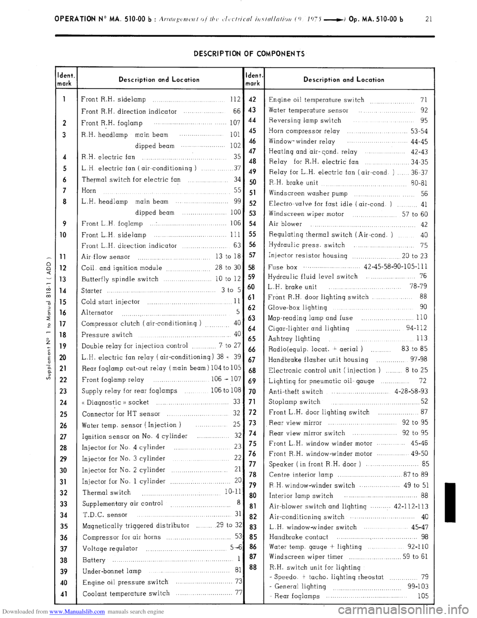
Downloaded from www.Manualslib.com manuals search engine OPERATION No MA. 510-00 b : A,.,.N//~w~/w/ of I/J<, c~l~~clriccrl iti7tollnliou (0 1075 -i Op. MA. 510-00 b 21 DESCRIPTION OF COMPONENTS
dent.
lark Description and Location Ident.
mark Description and Location
1
Front R.H. sidelamp ............................ 112 42
Engine oil temperature switch 71 ...............
Front R.H. direction indicator .... ... .........
66 43 Water temperature sensor .... .............. 92
2 Front R.H. foglamp 107 44 Reversing lamp switch ................... 95
..................... ....... ....
3 R.H. headlamp main beam
;:: :: Horn compressor relay ..................... 53-54
............... ....
dipped beam Window- winder relay .................. 44-45
......................
47
Heating and air-cond. relay ...............
4 R.H. electric fan ............................... 35 42-43
48
.............. 34-35
5 LH electric fan ( air--conditioning ) Relay for R.H. electric fan
........ 37 49
Relay for L.H. electric fan (air-cond. ) ..... 36-37
6 Thermal switch for electric fan .............. 34 50
R.H. brake unit
........... 80-81
......... ............
7 Horn
....................................
.......... ..... 55 51
Widscreen washer pump .............. .... 56
8 L.H. headlamp main beam ........... ..........
gg 52 Electra-valve for fast idle (air-cond. ) ......... 41
dipped beam ......................
100 53
Windscreen wiper motor ............. 57 to 60
9 Front L.H. foglamp ... . ...............................
106 54
Air blower ..............
........... ..... ........... 42 10
Front L.H. sidelamp ......................... ... ... .. 111 55 Regulating thermal switch (Air-cond. ) .... 40
Front L.H. direction indicator
63 56 ................... Hydraulic press. switch .......................
75 11
Air-flow sensor 13 to 18 57
........................... ... Injector resistor housing .................... .20 to 23 12
Coil. and ignition module
28 to 30 58 Fuse box ............................ 42-45-58-90-105-l 11
................. 13
Butterfly spindle switch 10 to 12 S9 Hydraulic fluid level switch ...................... 76
.................... 14
Starter 3 t0 5 6o L.H. brake unit ........................ 78-79
..........................................
88 15
Cold start injector 11 61 Front R.H. door lighting switch ....... ....
.................................. 16
Alternator 5 62 Glove-box lighting ................................ 90
...........
....... ..................... ....... 17
Compressor clutch ( air-conditioning ) 40 63 Map-reading lamp and fuse ............... ..... ... 110
.........
64 18
Pressure switch 40 Cigar-lighter and lighting ...................... 94-l 12
........................................
65 Ashtray lighting 113 ..................................... 19
Double relay for injection control 7 to 27 ............ 66
Radio(equip. locat. t aerial ) .......... 83 to 85
20 L.H. electric fan relay (air-conditioning) 38 = 39 67
Handbrake flasher unit housing .............. 97-98 21
Rear foglamp cut-out relay (main beam) 104 to 105 68
Electronic control unit (injection ) ....... 8 to 25
22 Front foglamp relay ....................... .. 106 - 107 69
Lighting for pneumatic oil- gauge .............. 72
23
Supply relay for rear foglamps ............ 106 to 108 70
Anti-theft switch ............................ 4-28-58-93 24
u Diagnostic )) socket 52 ......... ....... ... ..... ........ 33 71 Stoplamp switch ...................................... 25
Connector for HT sensor 72 ................... 87
....................... 32 Front L.H. door lighting switch 26
Water temp. sensor ( Injection ) Rear view mirror ............................ 92 to 95
... 25 73
27
Ignition sensor on No. 4 cylinder 32 74 Rear view mirror switch ................... 92 to 95
............. 28
Injector for No. 4 cylinder ...................... 23 75 Front L.H. window winder motor .......... 45-46 29
Injector for No. 3 cylinder 22 76 Front R.H. window-winder motor .............. 49-50
...........................
......................... 85 30
Injector for No. 2 cylinder 21 77 Speaker ( in front R.H. door )
......................... 78 Centre interior lamp ............................... 87 to 89 31 Injector for No. 1 cylinder 20 ............................. 79 R H. window-winder switch .................... 49 to 51 32 Thermal switch
........... .......................... 10-11 8 o
Interior lamp switch .................... ................ 88
33 Supplementary air control ............................
8 81
Air-blower switch and lighting .......... 42-112-113 34 T.&c.
SenSOr ........................................... 31 82 Air-conditioning switch ............... ............ 40
35
Magnetically triggered distributor ........ 29 to 32 83
L.H. window-winder switch .....................
45-47 36
Compressor for air horns ............. ..... ......... 53 85 Handbrake contact ......................................... 98 37
Voltage regulator 5-6 86 Water temp. gauge + lighting ..................
92-110
....................................... 38
Battery 1 87 Windscreen wiper timer
.......................... 59 to 61
....................................................... 39
40
41
Under-bonnet lamp ........................................ 81 88 R.H. switch unit for lighting
Engine oil pressure switch 73 - Speedo. t tacho. lighting rheostat ............ 79
............................
99-103
Coolant temperature switch 77
- General lighting ................................
....... ....................
- Rear foglamps ..................................... 105
Page 377 of 394
Downloaded from www.Manualslib.com manuals search engine .
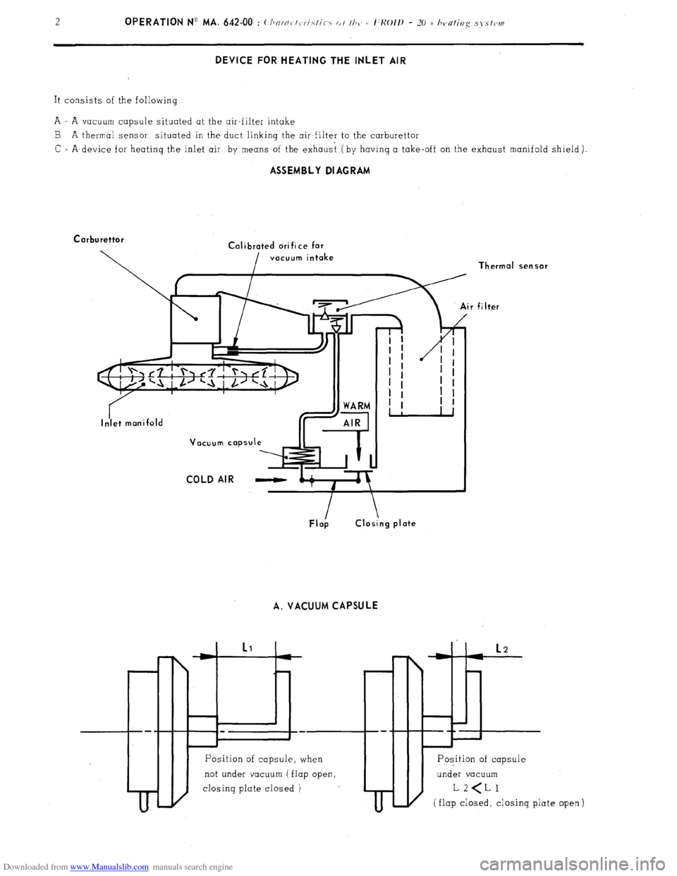
DEVICE FOR HEATING THE INLET AIR
It consists of the following
A - A vacuum capsule situated at the air-filter intake
B A thermal sensor, situated in the duct linking the air-filter to the carburettor
C - A,device for heatinq the inlet air by means of the exhaust (by having a take-off on the exhaust manifold shield). ASSEMBLY DIAGRAM
Carburettor
Calibrated ori fi ce for
vacuum intake
COLD AIR -
A. VACUUM CAPSULE
II I
I
t I
Position of capsule, when
not under vacuum ( flap open,
closing plate closed )
I
m-t L2
L-H ii
---+- Thermal
sensor filter
Position of capsule
under vacuum
(flap closed, closing
plate
open 1
Page 378 of 394
Downloaded from www.Manualslib.com manuals search engine OPERATION No MA. 642-W : ~Thnracteristics o/ thy, e I:Ko/I) - -70 3 hc,nriug s, stew Op. MA. 642-00 3
When starting : capsule is subjected to vacuum
Vacuum capsule
Westaflex tube
c J
J
COLD AIR
Closing plate for
SUPPLY SHUT OFF warm air supply
,
Flap B
I
to air filter
DIAGRAM.No. 1
‘acuum capsule not under vacuum
Flap
DIAGRAM No. 2
to air filter
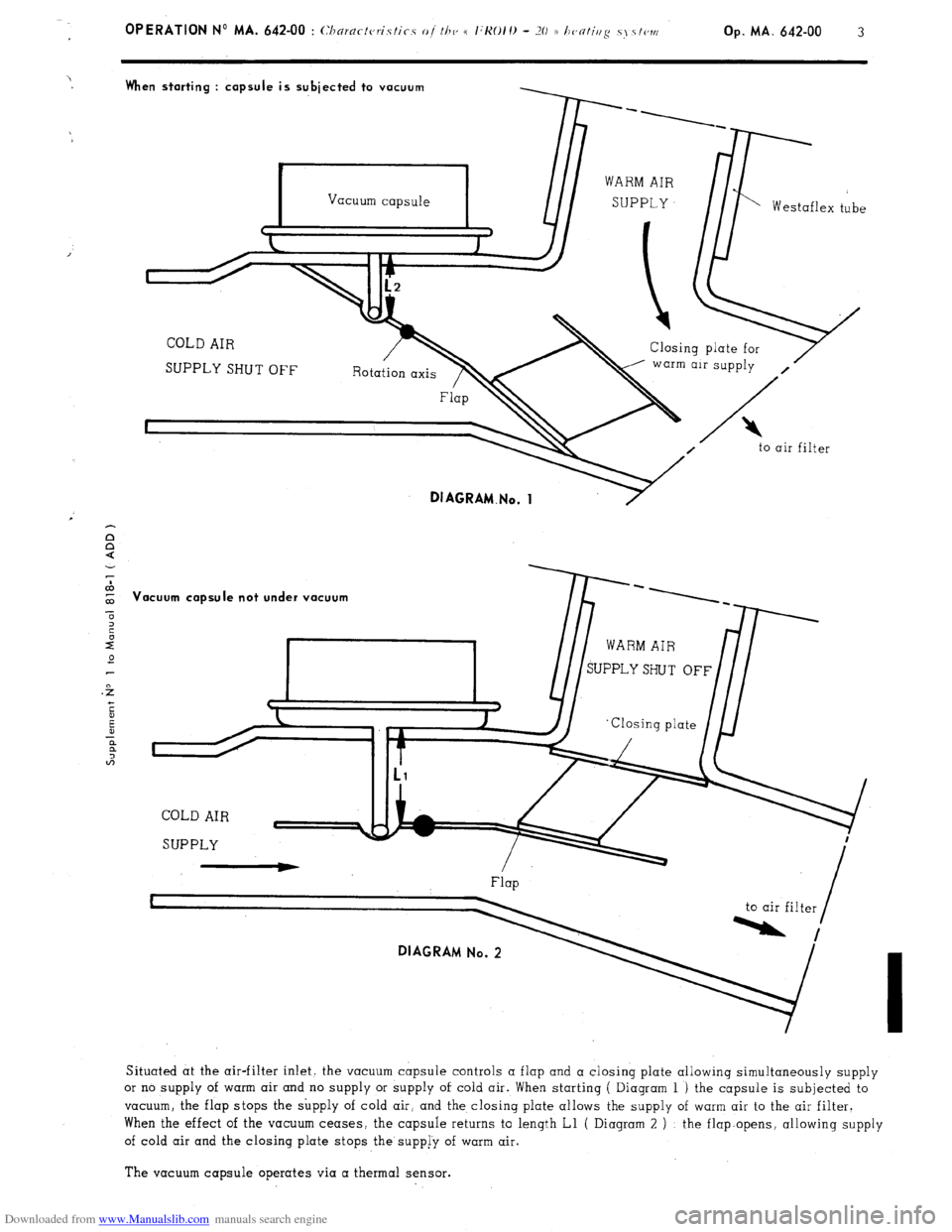
Situated at the air-filter inlet. the vacuum capsule controls a flap and a closing plate allowing simultaneously supply
or no supply of warm air and no supply or supply of cold air. When starting ( Diagram 1 ) the capsule is subjected to
vacuum, the flap stops the supply of cold air, and the closing plate allows the supply of warm air to the air filter.
When the effect of the vacuum ceases, the capsule returns to length Ll ( Diagram 2 ) : the flap.opens, allowing supply
of cold air and the closing plate stops the supp[y of warm air.
The vacuum capsule operates via a thermal sensor.
Page 379 of 394
Downloaded from www.Manualslib.com manuals search engine B. THERMAL SENSOR
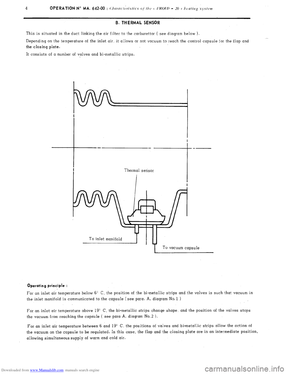
This is situated in the duct linking the air filter to the carburettor ( see diagram below ).
__
Depending on the temperature of the inlet air. it allows or not vacuum to reach the control capsule for the flap and
the closing plate.
It consists of a number of valves and bi-metallic strips.
To inlet manifoldb-yTu-4
I To vacuum capsule Operating principle :
For an inlet air temperature below 6’ C, the position of the bi-metallic strips and the valves is such that vacuum in
the inlet manifold is communicated to the capsule (see para. A, diagram No. 1 )
For an inlet air temperature above 19” C, the bi-metallic strips change shape. and the position of the valves stops
the vacuum from reaching the capsule ( see para A. diagram No.2 ).
For an inlet air temperature between 6 and 19” C, the positions of valves and bi-metallic strips allow the action of
the vacuum on the capsule to be regulated. In this case, the flap and the closing plate are in an intermediate position,
allowing simultaneous supply of warm and cold air.
Page 380 of 394
Downloaded from www.Manualslib.com manuals search engine Op MA. 642-00 5 II. DEVICE FOR INCREASING THE HEATING OF THE PASSENGER COMPARTMENT
This device entails modifying the following components
- Heater distribution box ( outlets towards side vents unplugged, different radiator )
Side vents with twin outlets ( ambient or heated air )
Addition of Westaflex ducts ( link from heater distribution box to side vents ). III. WATER TEMPERATURE GAUGE
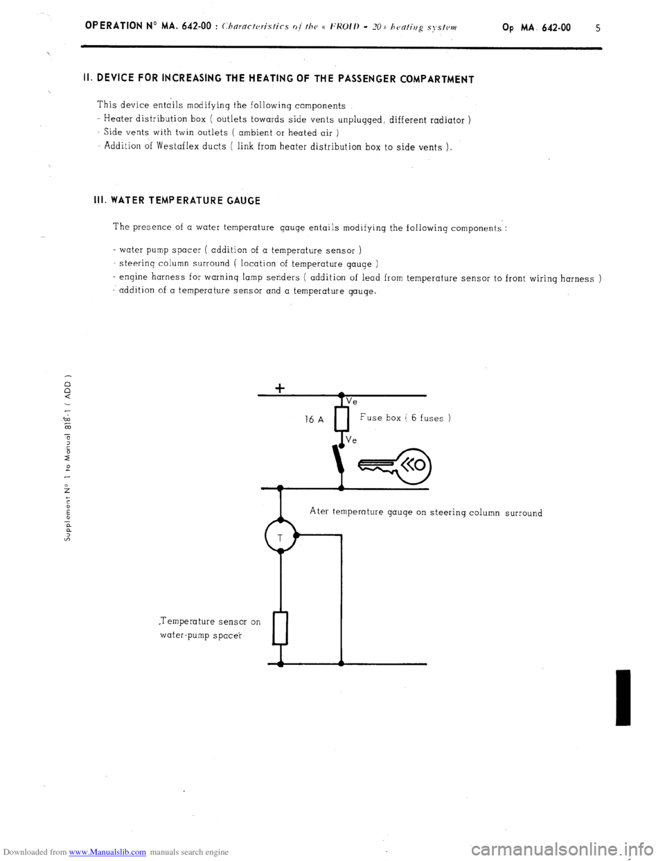
The presence of a water temperature gauge entails modifying the following components :
- water pump spacer ( addition of a temperature sensor )
steerinq column surround ( location of temperature gauqe )
- engine harness for warning lamp senders ( addition of lead from temperature sensor to front wiring harness )
addition of a temperature sensor and a temperature gauge.
Ater temperature gauge on steering column surround
.Temperature sensor on
water-pump spacer
P