relay Citroen CX 1981 1.G Workshop Manual
[x] Cancel search | Manufacturer: CITROEN, Model Year: 1981, Model line: CX, Model: Citroen CX 1981 1.GPages: 394
Page 86 of 394
Downloaded from www.Manualslib.com manuals search engine ALL CX VEHICLES
ANTI-POLLUTION SYSTEM ( SWEDISH MARKET )
I - cx 2200 :
The object of the system is to reduce the amount of unburnt hydrocarbons and the amount of CO in the exhaust
( 2 to 3 Z. of CO ) by injecting air under pressure into the exhaust manifold OPERATION :
As the engine rotates air pump ( 1 )supplies the air injectors (4) situated close to the exhaust valves: flap (3)
prevents the exhaust fumes from entering the air pump ( 1 ) and valve ( 2) assembly
There are two cases when it is necessary to stop the injection of air into the exhaust manifold. 1. During deceleration :
During fast decelerations. the mixture becomes richer combustion is incomplete, and the injection of air is
stopped in order 1.0 avoid a second combustion taking place in the exhaust system ( which would result in back
firinq ). During deceleration there is extreme low pressure downstream of the but!erfly ( 8 ). This in turn draws
in for a short period of time the diaphragm in valve (2 )
The air supplied by pump ( 1 ) is released into the atmosphere the calibrated hole u a )) on the diaphraqm
balances the pressure on either side of it, and the diaphragm returns to its initial position, allowinq air to
be once more injected into the exhaust manifold. 2. With the choke out :
With the choke in this position, the quantities of unburned hydrocarbons and CO are very considerable. It is
therefore necessary to stop the injection of air into the exhaust manifold so as to avoid an excessive
increase of temperature in the manifold. With the choke out, lever ( 5 ) connects relay ( 7 ) to earth.
The u WEBER )) electric contact is enerqized The air pressure at the outlet of air pump ( 1 ) increases the
effect of the low pressure on the diaphragm in valve (2 ) ( the air-pressure is felt above the diaphragm and
the low pressure produced by the carburettor (8) is felt below the diaphraqm ) the sliding valve in valve
unit ( 2 ) changes position, and the air is expelled into the atmosphere
If choke ( 5) is pushed back in, air is once again injected into the exhaust manifold.
Page 87 of 394
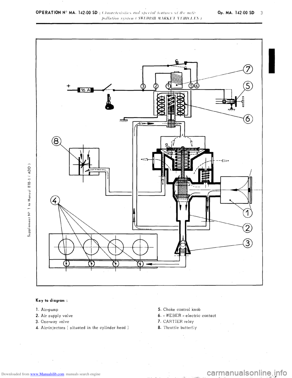
Downloaded from www.Manualslib.com manuals search engine Key to diagram :
1.
Air-pump 5. Choke control knob
2. Air supply valve 6. (( WEBER )) electric contact
3. One-way valve 7. CARTIER relay
4. Air-injectors ( situated in the cylinder head ) 8. Throttle butterfly
Page 88 of 394
Downloaded from www.Manualslib.com manuals search engine II. cx 2000
The object of the system is t3 reduce the amount of unburnt hydrocarbons and the amount of CO in the exhaust
( approximately 2 to 3
of CO ) by injectinq air under pressure into the exhaust manifold
OPERATION :
As the enqine rotates air pump ( 12) supplies the air injectors located near the exhaust valves: flap ( 13 )
prevents the exhaust fumes from entering the air pump and air supply duct assembly.
There are two cases where it is necessary to stop the injection of air into the exhaust manifold.
1. During deceleration :
Durinq fast deceleration. the mixture becomes richer combustion is incomplete and the injection of air is
stopped in order to avoid a second combustion takinq
place in the exhaust system ( which would result in
back-firinq ) Durinq deceleration there is extreme low pressure downstream of the butterfly ( 1 ). This in
turn draws in for a short period of time the diaphragm in valve ( 11 )
The air supplied by pump ( 12 ) is released into the atmosphere, the calibrated hole (( a 1) on the diaphragm
balances the pressure on either side of it and the diaphraqm returns to its initial position, allowinq air to
be once more injected into the exhaust manifold
2. With the choke out, for an engine coolant temperature of above 45’ + 3’ C, and whenever the coolant tempe-
rature remains above 35’ i “,I C.
In this situation the quantities of unburnt hydrocarbons and CO are very considerable It ‘is therefore necessary
to stop the injection of air into the exhaust manifold so as to avoid any excessive increase of temperature in
the manifold. On CX 2000 vehicles, injkction of air will be stopped when the enqine water temperature reaches
45” + 3- C Thermal switch ( 8 ) opens, relay ( 9 )
1s no lonqer enerqized. but electro-valve ( 7 ) remains live
( relay lead ). and is earthed via the choke control
The air pressure at the outlet of air-pump ( 12 )
increases the effect of the low pressure on the diaphraqm in
valve ( 11 ) ( the air pressure is felt above the diaphraq,m, and the low pressure produced by the carburettor (2)
is felt below the diaphraqm ). the slidinq valve in the duct chanqes position and the air is expelled into the
atmogphere If the choke ( 10) is pushed back in air is once again injected into the exhaust manifold
DEVICE FOR OPENING THE BUTTERFLY :
The object of the device is to maintain combustion during sudden deceleration up to an enqine speed
of
Nd 7 1800 + 100 rpm.
Durinq deceleration for any enqine speed above Nd, the electronic tachometer housinq ( 6 ) earths the
windinq of relay ( 5) Therefore the H PIERBURG 1) electro-valve ( 4) is no lonqer enerqized. Electro-
valve ( 4) is then under low-pressure, below the diaphragm of the device ( 3 ) for opening the butterfly
When the decreasinq enqine speed falls below
Nd, the electronic tachometer housing (6 ) cuts out the
earth of the winding in relay ( 5) Therefore the (( PIERBURG )) electro-valve ( 4) is enerqized The
electro-valve is no lonqer under low pressure below the diaphraqm of the device (3) for openinq the
butterfly the throttle butterfly returns to it s stop aqainst the idlinq speed adjustment screw. The dia-
phraqm of the device (3) for openinq the butterfly will once aqain be affected by low pressure ( under
the control of the electronic tachometer housing ) once the increasing engine speed reaches
NC ~ Nd t 50 to 250 rpm
Page 89 of 394
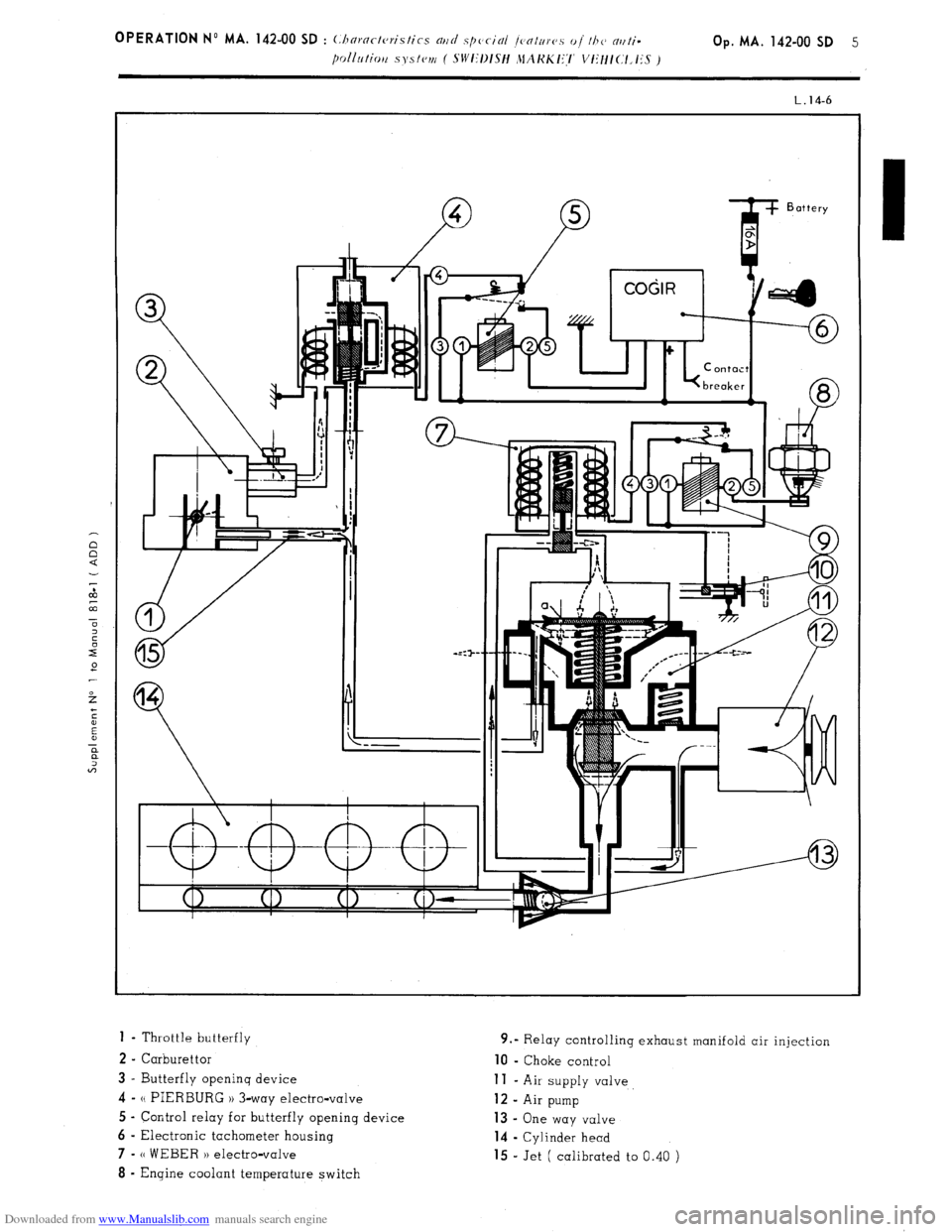
Downloaded from www.Manualslib.com manuals search engine 1 - Throttle butterfly
2 - Carburettor
3 - Butterfly openinq device 4-
N PIERBURG 1) 3-way electro-valve
5 - Control relay for butterfly opening device
6 - Electronic tachometer housing 7-
(( WEBER H electro-valve 8
- Engine coolant temperature switch 9.” Relay controlling exhaust manifold air injection 10
- Choke control
11 - Air supply valve 12
- Air pump 13 -
One way valve
14 - Cylinder head
15 - Jet ( calibrated to 0.40 )
Page 94 of 394
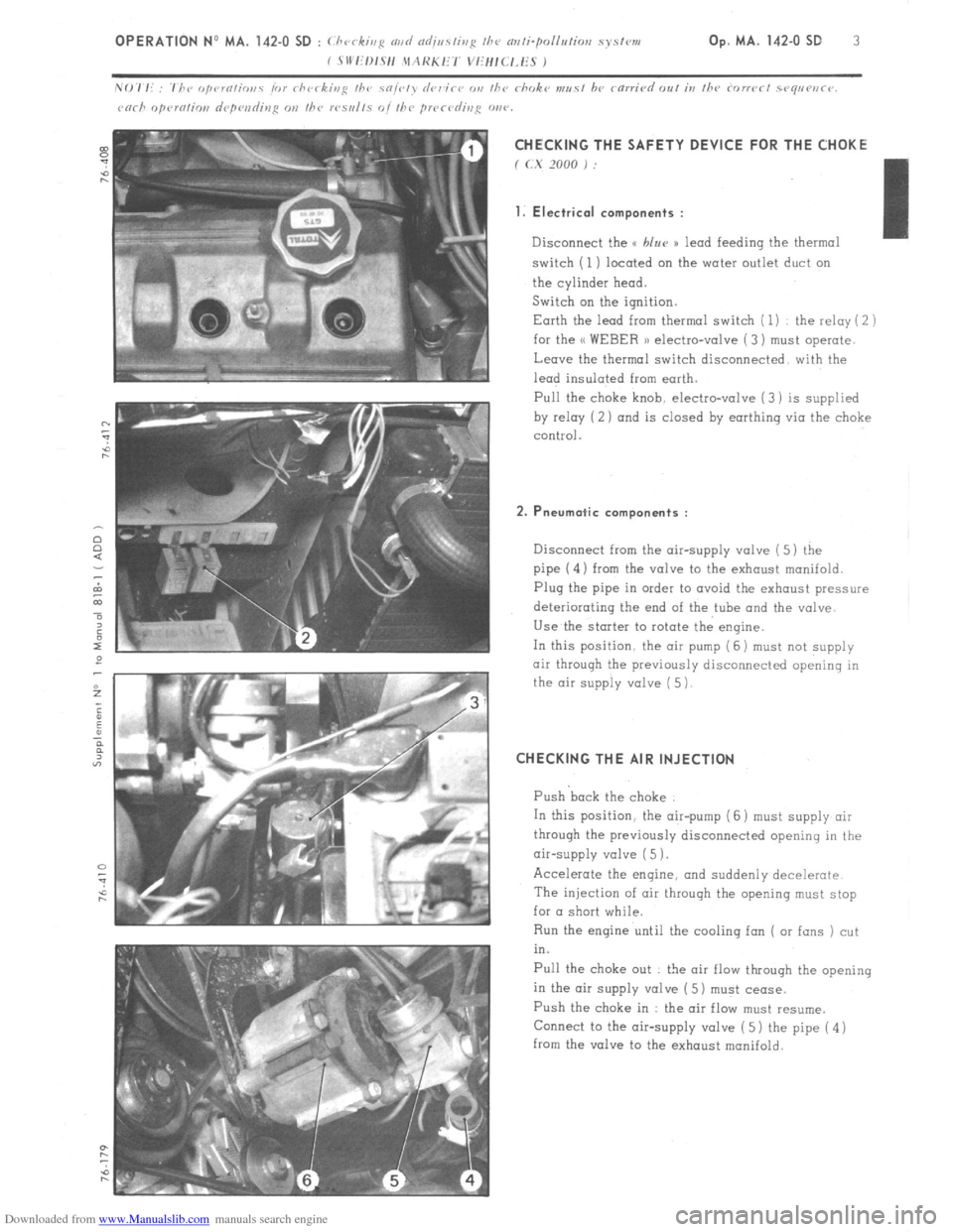
Downloaded from www.Manualslib.com manuals search engine CHECKING THE SAFETY DEVICE FOR THE CHOKE
f (.X 2000 j :
1. Electrical components :
Disconnect the u blur )) lead feeding the thermal
switch (1) located on the water outlet duct on
the cylinder head.
Switch on the ignition.
Earth the lead from thermal switch ( 1) the relay ( 2 )
for the << WEBER 1) electro-valve ( 3) must operate.
Leave the thermal switch disconnected with the
lead insulated from earth.
Pull the
choke knob. electro-valve (3) is supplied
by relay (2 ) and is closed by earthing via the choke
control.
2. Pneumatic components :
Disconnect from the air-supply valve ( 5) the
pipe (4) from the valve to the exhaust manifold.
Plug the pipe in order to avoid the exhaust pressure
deteriorating the end of the tube and the valve
Use the starter to rotate the engine.
In this position. the air pump (6 j must
not supply
air through the previously disconnected opening in
the air supply valve ( 5)
CHECKING THE AIR INJECTION
Push back the choke
In this position. the air-pump (6 ) must supply air
through the previously disconnected opening in the
air-supply valve ( 5 1.
Accelerate the engine, and suddenly decelerate
The injection of air throuqh the opening must stop
for a short while.
Run the engine until the cooling fan ( or fans ) cut
in.
Pull the choke out : the air flow through the opening
in the air supply valve ( 5) must cease.
Push the choke in : the air flow must resume.
Connect to the air-supply valve ( 5) the pipe ( 4 )
from the valve to the exhaust manifold.
Page 95 of 394
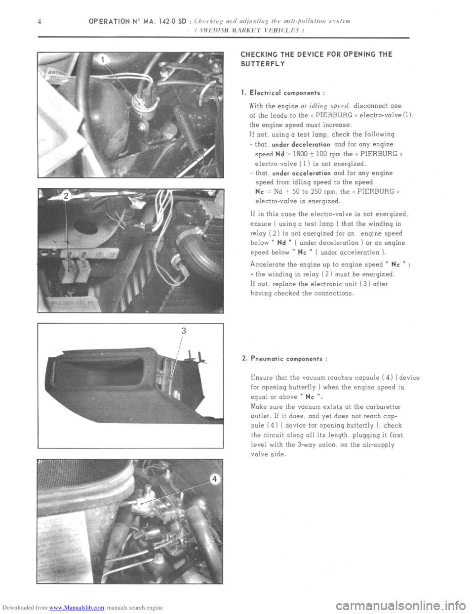
Downloaded from www.Manualslib.com manuals search engine CHECKING THE DEVICE FOR OPENING THE
BUTTERFLY
1. Electrical components :
With the engine at idling spu~d. disconnect one
of the leads to the C< PIERBURG ,) electro-valve (1).
the engine speed must increase.
If not. using a test lamp, check the following
that.
under deceleration and for any engine
speed
Nd > 1800 ? 100 rpm the /C PIERBURG >l
electro-valve (1 ) is not energized.
- that.
under acceleration and for any engine
speed from idling speed to the speed
Nc = Nd + 50 to 250 rpm. the C< PIERBURG ,,
electro-valve is energized.
If in this case the electro-valve is not energized.
ensure ( using a test lamp ) that the winding in
relay ( 2) is not enerqized for an engine speed
below ”
Nd ” ( under deceleration ) or an engine
speed below ”
NC ” ( under acceleration ).
Accelerate the engine up to engine speed ”
NC n :
- the winding in relay (2 ) must be enerqized.
If not. replace the electronic unit (3) after
having checked the connections.
2. Pneumatic components :
Ensure that the vacuum reaches capsule ( 4 1 ( device
for opening butterfly ) when the engine speed is
equal or above ”
NC “.
Make sure the vacuum exists at the carburettor
outlet. If it does. and yet does not reach cap-
sule (4) ( device for opening butterfly 1. check
the circuit along all its length. plugging it first
level with the 3-way union. on the air-supply
valve side.
Page 98 of 394
Downloaded from www.Manualslib.com manuals search engine 2
OPERATION No MA.IE. 144-00 : Chtiractcristics o/ the e 1,-Jc,tror,ic H clcctroltic
fire1 injc ctiwt systettt.
((L-JETRONIC,,
The H L-Jetronic 1) system is’an intermittent low-pressure injection system which injects petrol into the inlet
manifold.
The system measures the quantity of air drawn in by the engine. which is the main parameter for calculating
the amount of fuel. to be injected. The metering of the fuel is carried out by electro-magnetically triggered
injectors. These are under constant fuel pressure. The quantity of fuel injected is proportional to the duration
of injection. which in turn is optimally determined for any given engin& operating condition by an electronic
control unit ( E.C.U. ) from information supplied by several electric sensors.
One of the principal contributions of the H L-Jetronic H system is the reduction in the level of pollution of the
exhaust emissions.
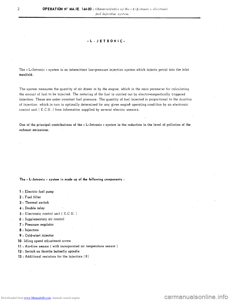
The (( L-Jetronic v system is made up of the following components :
1
: Electric fuel pump
2 : Fuel filter
3 : Thermal switch
4 :, Double relay
5 : Electronic control unit ( E.C.U. )
6 : Supplementary air control
7 : Pressure regulator
8 : Injectors
9 : Cold-start injector
10. Idling speed adjustment screw
11 : Air-flow sensor ( with incorporated air temperature sensor )
12 : Switch on throttle butterfly spindle
13 : Additional resistors for the injectors (8)
Page 132 of 394
Downloaded from www.Manualslib.com manuals search engine 1. Energizing the system : ( DIAGRAM 1 )
_ Disconnect the E.C U
- Switch the ignition on
Using a voltmeter. ensure that each point in
dingrm 1 is effectively energised. after having tested the
earthing. If not, switch off the ignition. and test the circuit using a battery operated ohmmeter. With the
voltmeter connected between terminals ( 1 ) and ( 5) of the E. C.U., operate the starter the voltmeter must
register the ignition impulses If it does not. check the ignition
( ANNEXE A ).
2. Fuel pump feed ( on operating the starter ) ( DIAGRAM 2 )
- Disconnect the E C.U.
- Switch on the ignition
- On operating the starter. the fuel pump (
secureri rrt/rler the I c~hiclc’. uoor IIJO K. ti. ronr (, l~eol I must be
heard to operate by someone standing close by
If not switch off the ignition, and test the circuit using a battery operated ohmmeter.
The resistance between terminal (( 88 d H of the relay assembly ( c~r~tler 111~
L,H. honr/llor)~p ) and earth
must be 1 Q approx-
Make sure the petrol pump is properly earthed.
Page 135 of 394
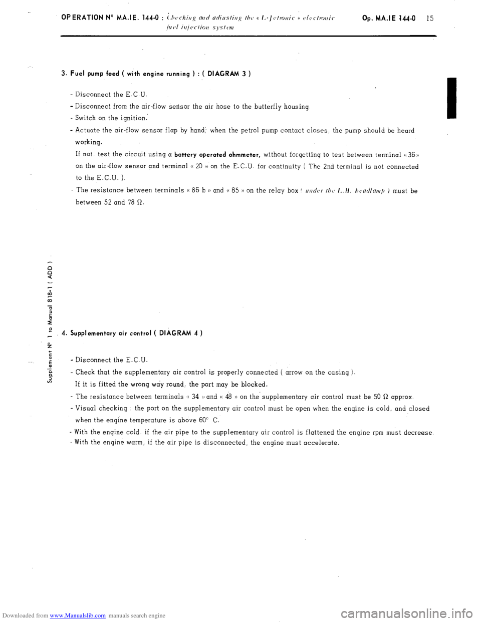
Downloaded from www.Manualslib.com manuals search engine Op. MA.IE 444-O 15
3. Fuel pump feed ( with engine running ) : ( DIAGRAM 3 )
- Disconnect the E.C.U.
- Disconnect from the air-flow sensor the air hose to the butterfly housing
- Switch on the ignition:
- Actuate the air-flow sensor flap by hand’ when the petrol pump contact closes the pump should be heard
working.
If not, test the circuit using a
battery operated ohmmeter, without forgetting to test between terminal G 36 ))
on the air-flow sensor and terminal H 20 .)) on the E.C.U. for continuity ( The 2nd terminal is not connected
to the E.C.U. ).
- The resistance between terminals (( 86 b H and G 85 )) on the relay box f //j/nor thc~ I~./I. h<~ntllnr~tp ) must be
between 52 and 78 12.
P 4. Supplementary air control ( DIAGRAM 4 )
4
c
5
6
- Disconnect the E.C.U.
-E
? - Check that the supplementary air control is properly connected ( arrow on the casing )~
In
If it is fitted the wrong way round. the port may be blocked.
- The resistance between terminals (( 34 1, and (( 48 )) on the- supplementary air control must be 50 Q approx-
- Visual checking the port on the supplementary air control must be open when the engine is cold, and closed
when the engine temperature is above 60” C
- With the engine cold. if the air pipe to the supplementary air control is flattened the engine rpm must decrease.
With the engine warm, if the air pipe is disconnected, the engine must accelerate.
Page 289 of 394
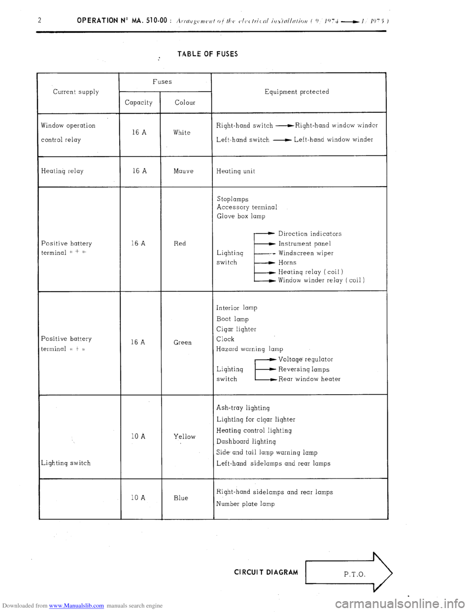
Downloaded from www.Manualslib.com manuals search engine TABLE OF FUSES
Current supply
findow operation
ontrol relay Fuses
Equipment protected
Capacity Colour
Right-hand switch -Right-hand window winder
16 A White
Left-hand switch - Left-hand window winder
Ieating relay 16 A Mauve Heating unit
Stoplamps
Accessory terminal
Glove box lamp
‘ositive battery
erminal (( + )). 16
A Red Direction indicators
E Instrument panel
Lighting -- Windscreen wiper
switch Horns
Heating relay ( coil )
Window winder relay ( coil )
‘ositive battery
erminal (( t 1) 16 A Green Interior lamp
Boot lamp
Cigar lighter
Clock
Hazard warning lamp
Lighting
switch
E
Voltage’ regulator
Reversing lamps
Rear window heater
Ash-tray lighting
10 A Yellow Lighting for cigar lighter
Heating control lighting
Dashboard lighting
,ighting switch Side- and tail lamp warning lamp
Left-hand sidelamps and rear lamps
10 A Blue Right-hand sidelamps and rear lamps
Number plate lamp Cl RCUI T DIAGRAM
r>