torque Citroen CX 1981 1.G Repair Manual
[x] Cancel search | Manufacturer: CITROEN, Model Year: 1981, Model line: CX, Model: Citroen CX 1981 1.GPages: 394
Page 329 of 394
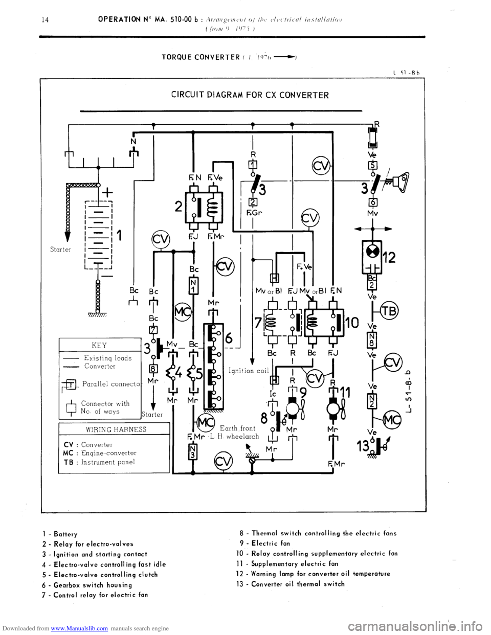
Downloaded from www.Manualslib.com manuals search engine TORQUE CONVERTER ( I ‘/+(I -I
1 51-Rh
CIRCUIT DIAGRAM FOR CX CONVERTER
kd i- I I I c
I I Bc Bc
*
KEY
- Existinq leads G
- Converter
6
8
;a
Parallel connecto- Mr
0 Connector with
No. of ways i
Starter
01 ---
I Bc k l3i F;J
E Mr ,L H wheelarch
A m
I 1
EMr
to TB
Ve
P n
Ve +
1 - Battery
2 - Relay for electro-valves
3 - Ignition and starting contact
4 - Electra-valve controlling fast idle
5 - Electra-valve controlling clutch
6 - Gearbox switch housing
7 - Control relay for electric fan 8 - Thermal switch corrtrolling the electric fans
9 - Electric fan
10 - Relay controlling supplementary electric fan
11 - Supplementary electric fan
12 - Warning lamp for converter oil temperature
13 - Converter oil thermal switch
Page 348 of 394
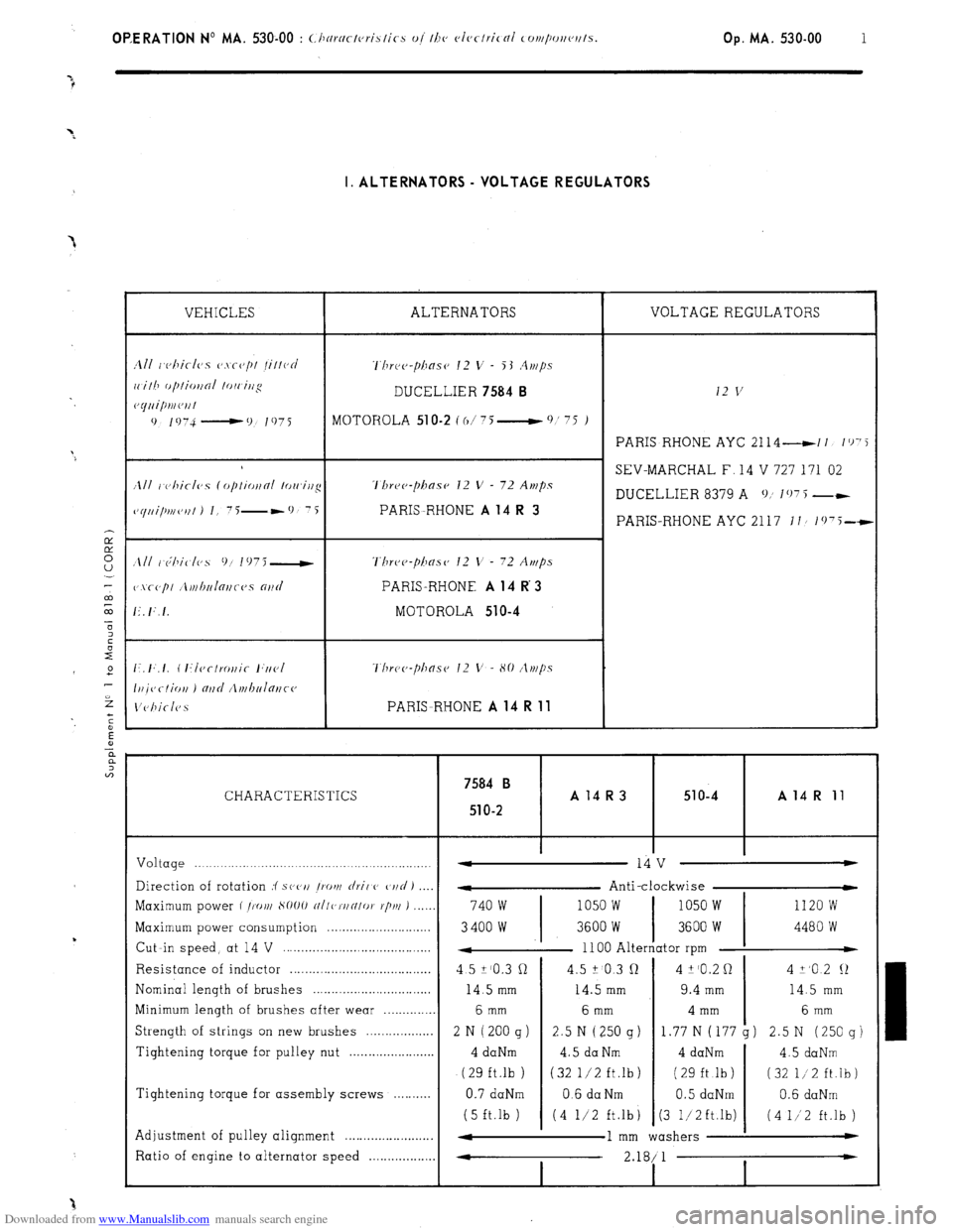
Downloaded from www.Manualslib.com manuals search engine OP,ERATlON No MA. 530-00 : <.Ilnrnctc,rislics oj I/IV cJlec/rical cor~~/~~r~c~~t/s. Op. MA. 530-00 1 I. ALTERNATORS - VOLTAGE REGULATORS
VEHICLES ALTERNATORS VOLTAGE REGULATORS
1111 r~c,hicl(~s CJ.\~(J/)/ /il/ocJ ‘l’hrc~c~-pilasc~ 12 v - 53 .4r,/ps
ri.ilh f~/~IioI~oI lo/i irjg DUCELLIER 7584 B 12 v c~yuipmc~ril
0 1 !, 74 - 0 I 97 i
MOTOHOLA 51 O-2 C o/ 75 __t 0 ’ ‘5 )
PARIS RHONE AYC 2114 -11 I’)‘5
SEV-MARCHAL F, 14 V 727 171 02
/Ill I c)hiclvs (opliotfni lowirtg ‘l’hre~~-phase 12 V - 72 Amps
DUCELLIER 8379 A 0; 107 5 --
~~yui/mc,,fl J I, 7i-*9 7i PARIS-RHONE A 14 R 3 PARIS-RHONE AYC 2117 II/ 1(j75-t
Three-phase’ 12 V - 72 Amps
PARIS-RHONE A 14 R 3
MOTOROLA 510-4
Thr~~~~-pha.s~~ 12 V - 80 /lt)t/?s
PARISRHONE A 14 R 11
7584 B CHARACTERISTICS A14R3 51 o-4 A 14 R 11
51
O-2
Voltage .._._._.._._.._____.......................,...................,. -
14 v w
Direction of rotation :f s(‘(‘I/ /rot)/
rlril C’ C,I/C/ J
- Anti-clockwise
Maximum power f /X),/I S1)OO
~/I/c,~/IN/oI. r/j/u ) ..,__, 740 w 1050 w 1050 w 1120 w
Maximum power consumption . . . . . .._..__.______........
3400 w 3600 W 3600 W 4480 W
Cut -in speed, at 14 V . .
4 1100 Alternator rpm t
Resistance of inductor . .
4 5 Z’O.3 cl 4.5 ? 0.3 Q 4 k’O.2 0 4 +,o 2 12
Nominal length of brushes .
14.5 mm 14.5 mm 9.4 mm 14.5 mm
Minimum length of brushes after wear . . 6 mm 6 mm 4 mm 6 mm
Strength of strings on new brushes . . . . . . . . . . . . . . . . . 2 N ( 200 g ) 2.5 N (250 g)
1.77 N (177 g) 2.5 N (250 g)
Tightening torque for pulley nut . . 4 daNm 4.5 da Nm 4 daNm
4.5 daNm
(29 ft.lb ) (32 l/2 ft.lb) ( 29 ft .lb ) (32 l/2 ft.lb)
Tightening torque for assembly screws .
0.7 daNm 0.6 da Nm 0.5 daNm 0.6 daNm
(5 ft.lb ) (4 l/2 ft.lb
j (3 1,‘2ft.lb) (4 1/‘2 ft.lb )
Adjustment of pulley alignment . . . . . . . . . . . . . . . . . . . . . . . . 4
1 mm washers w
Ratio of engine to alternator speed . . . 4
2.18/ 1 *
I I
Page 350 of 394

Downloaded from www.Manualslib.com manuals search engine OPERATION No MA. 530-00 : (./Jo).N~.I(,I.;sI~~-s I>/ I/I<> vfvctrir-nl c~NI/~~~I/~~~IIs.
Op. MA. 530-00 3
III. STARTER MOTORS.
ALL ENGINES
DUCELLIER 6236 AND PARIS-RHONE D 9 E 16 STARTERS
CHARACTERISTIC CURVES
daNm
0.5 - 5
0 =f N
?l!fBl 7
a3
2
Trrt rt-ul I I I I / I 1 0
? I s1
2 -I
2 ’ I I III I I I I
F
200 400 600 800 1 AMPS
2
1000 2000 3000 4000 N RPM ;
E
r:
z, CHECKING.
ON VEHICLE : Ensure that battery is fully charged, and measure the following :
a) Current consumed,( pinion locked ) ._... . . . . . . . . .: . . . . . . . . . . . . . . . . . . . . . . . . . . 440 A ( 6236 ) and 450 A ( D 9 E 1 6 )
b) Current consumed when starting ( at 20’ C ) . . . . . . . . . ,.......,........................... 150 to 170 A
c) Current consumed with no load ( starter removed ) ,.,.,.,. ..,.,. ,...,.,...,.....,.,.,.,.,.,. 50 A maximum
BENCH TEST
: Use a 12 V - 200/40 Ah fully charged battery.
MEASUREMENTS
. Average torque at 1000 rpm _ .................................................................
Corresponding current ._ ............................................................... ......
. Torque locked ............................ ........................ ........................ ............
Corresponding current ._ ........................... ...... ............ ......................
Voltage ..................................................... ...... ........................................
Maximum power ._ ........................................................... ..........................
Voltage ....................................................................................................
Current .............................................................................................
Torque ._ ................................................................................................... DUCELLIER PARIS-RHONE
6236 D9E16
1.85 daNm (6 1 ft.lb)
300 A
.15 daNm (1.08 ft.lb)
440 A.
7.4 v
965 W
9.4 v
240 A
1.6 daNm ( 4.3 ft.lb) 1.83 daNm (6 ft.lb)
270 A
1.155daNm (1.12 ft.lb)
,450 A
7v
920 w
9v
215 A
0.6 daNm (4.3 ft.lb)
Page 351 of 394
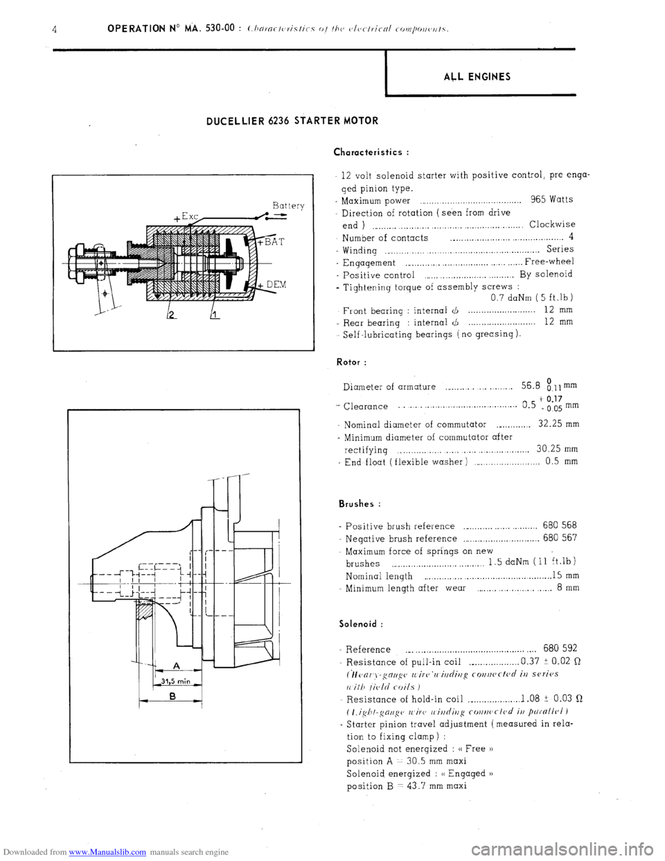
Downloaded from www.Manualslib.com manuals search engine DIJCELLIER 6236 STARTER MOTOR
Ch aracteristics :
Battery
+ E xc,-.L
I ALL ENGINES
12 volt solenoid starter with positive control, pre-enga-
ged pinion type.
- Maximum power ,.,..................................... 965 Watts
Direction of rotation (seen from drive
end ) ,.,_,.,.,. ..,.,...,.,. ,.,.,.,...._ . . . . .._...... .,.,. Clockwise
Number of contacts ._.,.,.,.,.,.,_........ ..,.,.,............. 4
- Winding ._.,.,......... ,.,.,.,_......,.,.....,.,...............~... Series
- Engagement ,~.,.,...,... ,.,............... . Free-wheel
- Positive control ,.,.,. . . . . . . . . . . ..,.,.,... By solenoid
- Tightening torque of assembly screws :
0.7 daNm ( 5 ft,lb)
Front bearing : internal d . . . 12 mm
- Rear bearing : internal <,!J 12
mm
Self -lubricating bearings ( no greasing ). Rotor :
Diameter of armature ,_,.,.,. .,. _..._.... 56.8
8.11 mm
‘- Clearance ... . . . . . . . . . . . .
t 0.17 0.5 e005mm
- Nominal diameter of commutator ._._...,.,.,. 32.25 mm
- Minimum diameter of commutator after
rectifying . . . . . . . . . . . . . . . . . . . . . 30.25 mm
End float (flexible washer) ,.........,.,.,..._.....,. 0.5 mm Brushes :
Positive brush reference ._._.,.,... ,..... . . . . . 680 568
Negative brush reference ..,.,.,.,.,.,.,............... 680 567
Maximum force of springs on new
brushes . . . . . . . . . . . . . . . . . . . . . . . . . . . . . 1.5 daNm (11 ft.lb)
Nominal length . . . . ._.............,...............~. 15 mm
Minimum length after wear ., . . . . . . . . 8
mm Solenoid :
- Reference ._. ,.,..............~........................ .,.. 680 592
Resistance of pull-in coil ,_...,.,.........,. 0.37 i 0.02 Q
(lfc~or~j-gctup (L irc~‘rc iltdittg co~~rtcftc~d it/ series
11 ill7 /ic,ld coils I
Resistance of hold-in coil ,_...,...,.......... 1 .08 ? 0.03 Q
( I.igh!-~oll~c~ /l~iF(, I, ittditlg cottrtc~cl<~d
it/ parnllr~l )
- Starter pinion travel adjustment (measured in rela-
tion to fixing clamp) :
Solenoid not energized : (( Free H
position A 30.5 mm maxi
Solenoid energized : u Engaged u
position B 7 43.7 mm maxi
Page 352 of 394
Downloaded from www.Manualslib.com manuals search engine 1 ALL ENGINES
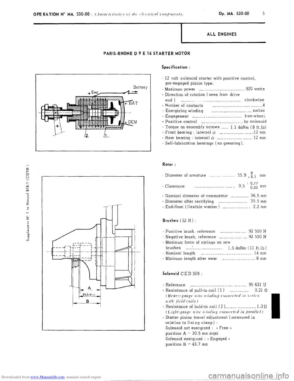
PARIS-RHONE D 9 E 16 STARTER MOTOR
Battery Specification :
- 12 volt solenoid starter with positive control,
pre-engaged pinion type.
- Maximum power ,..... ,................................. 920 watts
- Direction of rotation ( seen from drive
end ) ., . . . ._..,.,...,.,..................... clockwise
- Number of contacts __..... . . . . . . . . . . . . . . . . . . . . . . . . . . . 4
- Energizing winding . . . . . . . . . . . . . . . . . . . . . . . . . . . . . . . . . . series
- Enqagement ,“...,.,.........,.,.............,......... free-wheel
- Positive control ._.,.,.,.,.,.,.......,.,.,....... . by solenoid
- Torque on assembly screws . . . . . . 1.1 daNm (8 ft.lb)
- Front bearing : internal 4 ,..._.,.....,...,.,.,. _....._. 12 mm
- Rear bearing : internal $I ._...,...,...,.,.,.,. ,.....,. 12 mm
- Self-lubrication bearings ( no greasing ). Rotor :
Diameter of armature . . . . . . . . . . . . . . . 55.9 - ;.I mm
- Clearance _.......................... . . . . . . 0.5 ’
0.17
0.05 mm
- “Jominal diameter of commutator . . . . . . . . . . . . . . . . 36.5 mm
- Diameter after rectifying ,.....,................... 35.5mm
- End-float (flexible washer) ,....._.,... . . . 2.2 mm Brushes (52
R) :
- Positive brush, reference . . . . . . . . . . . . . . 92 550 N
- Negative brush, reference ,...,.,.,.,.,. ,.,.,. . . . 92 550 N
- Maximum force of springs on new
brushes ,... ..I. . ,. ,. . . . ..,......... 1.5 daNm (11 ft.lb)
- Nominal length
,... . . . . . . .., . . . . . . . .,......... 14 mm
- Minimum length after wear . . . . . . . ..,......... 8 mm Solenoid
CED 509 :
- R.eference . . . . . . . . . . . . . . . . . . . . . . . . . . . . . . . . . . . . . . . ,.,. 95 631 U
- Resistance of pull-in coil (1 ) . . . . . 0.21 Q
(Heaz’y-gauge wire IL’i?/dirzg cotlucctcd iu .sc,ricJs
with field coils )
- Resistance of hold-in coil ( 2 ) . . . . . . . . . . . . . . . . . . . . . . . . . . 1.3 Q
( Light-gc7zigc wire’ 11 itlrliug conwctcrl in pdrallrl )
- Starter pinion travel adjustment (measured in
relation to fixi ng clamp ) :
Solenoid not energized : (( Free ))
position A = 30.5 mm maxi
Solenoid energized : (( Engaged 1)
position B = 43.7 mm
Page 359 of 394
Downloaded from www.Manualslib.com manuals search engine OPERATION No MA. 560.0 : ~hrrkin~ o,,d oc/@s/i,,g I/><, wiurisrrrr,, wip’r. Op. MA. 560.0
1
Fi
m
0 CHECKING AND ADJUSTING THE WINDSCREEN WIPER.
FRONT WINDSCREEN WIPER MOTOR
CHARACTERISTICS.
Manufacturer DUCELLIER
Reference No. 4966 A
Field coils Ferrite
Armature : Endfloot (adjustable by means of stop-screw) : 0.2 mm
Nominal dia. of commutator :
24 mm
Min. dia. after machining : 23 mm
Brushes : Ref. No. :
CL 7239
Minimum length after wear : 5.5 mm
Ratio : .._...................................................................................................
44 1
Connection and circuit diagram as in Op. MA. 510 00.
ELECTRICAL CHECK. BOSCH
0390 346 127
Ferrite
0
23.2 mm
23 mm
1.394.320-058 059, 062
7.5 mm
49 1
1. First speed :
Nominal power : IO watts
Speed, under no load, at 13.5 volts = 50 rpm Corresponding current = I.8 A
Torque, motor locked, at 13.5 volts = 1.9 da Nm 7 13.74 ft.lb min. Corresponding current 18 A max.
Torque at 40 rpm and 13.5 volts = 0.2 do Nm (1.45 ft.lb) Correspondinq current = 5.5 A max.
- Torque ot 20 rpm and 13.5 volts = 1.07 da Nm (7.74 ft.lb) min Corresponding current = 13.2 A max.
2. Second speed :
Nominal power : 15 watts
Speed under no load at 13.5 volts = 70 rpm Corresponding current = 2.3 A
Torque motor locked at 13.5 volts = 1.5 do Nm (IO.85 ft.lb) min Corresponding current = 21 A max
Torque at 60 rpm and 13.5 volts = 0.2 da Nm (1.45 ft.lb) min Corresponding current = 7 A max
Torque ot 30 rpm and 13.5 volts = 0.9 da Nm (6.51 ft.lb) min Corresponding current = 14.7 A mrx.
ADJUSTMENT OF WINDSCREEN WIPER ARM
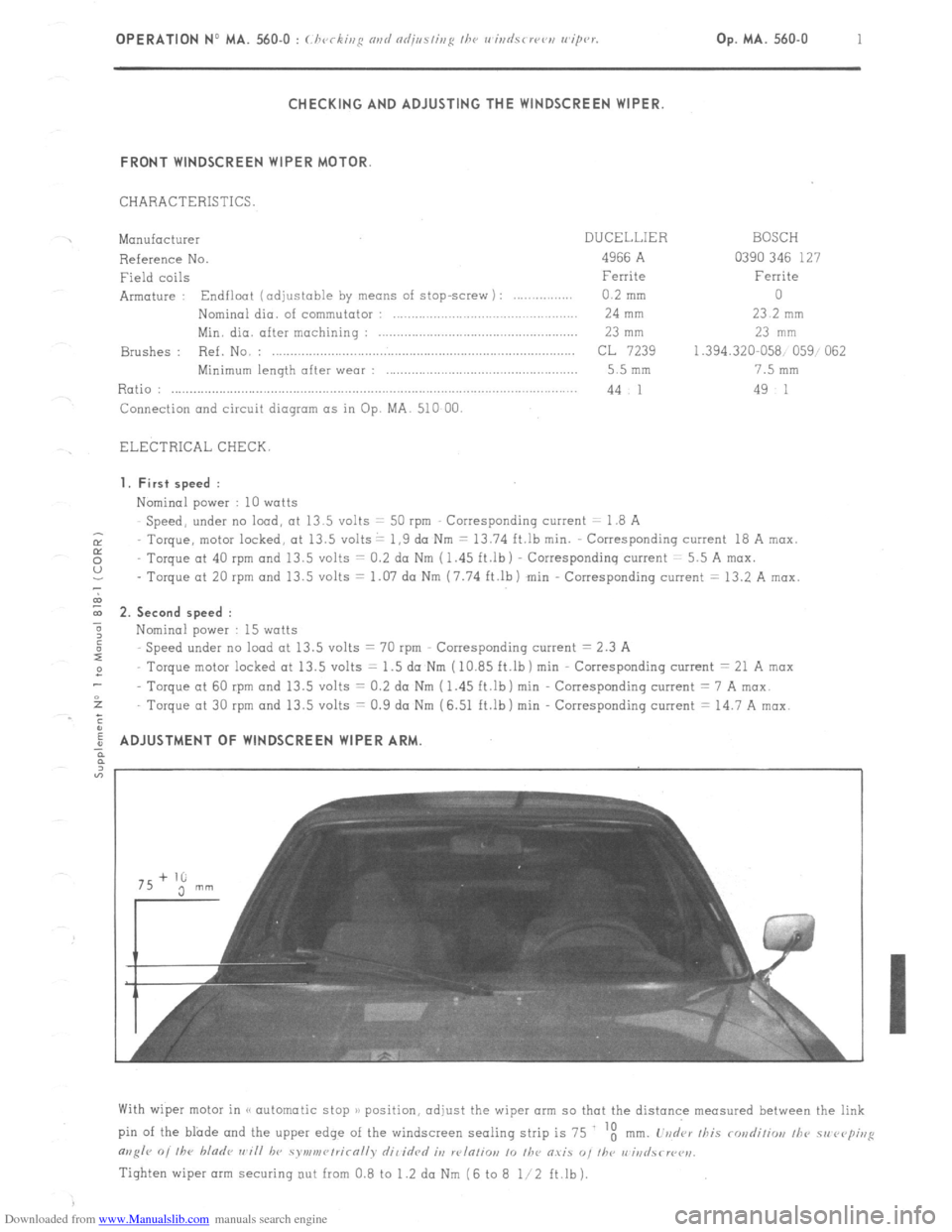
With wiper motor in (< automatic stop )/ position, adjust the wiper arm so that the distance measured between the link
pin of the blade and the upper edge of the windscreen sealing strip is 75 ‘t
mm. L’vd‘ar /his rondiliw, /he 51, rvp;,,g
m,g/r 0, /he bladr ,,~i// hv symv,r~/rirn//v dil idrd it, w/n/io,, 10 /he O.YiS “, I/w r,‘iri
Tighten wiper arm securing out from 0.8 to 1.2 da Nm (6 to 8 l/2 ft.lb).
Page 360 of 394
Downloaded from www.Manualslib.com manuals search engine 2 OPERATION No MA. 560-O : (:/ ivc ,,,* our/ nd;,,s/ii,~ ,,w I, ,,i
k’
REAR WINDSCREEN WIPER MOTOR (lislnlvs J
CHARACTERISTICS.
Mon”facturer ..,..._....,...........,.................................................................................................... BOSCH
~ef,yence
~0. . . . . . . . . . . . . . . . . . . . . . . . . . . . . . . . . . . . . . . . . . . . . . . . . . . . . . . . . . . . . . . . . . . . . . . . . . . . . . . . . . . . . . . . . . . . . . . . . . . . . . . . . . . . . . . . . . . . . . . . . .... WXP
12 V 0390
526 071
Field Coils
. . . . . . . . . . . . . . . . . .._............................................................................................................ Ferrite
Armature :
Endfloat ( “ot adj”stable ) . . . . . . . . . . . . . . . . . . . . . . . . . . . . . . . . . . . . . . . . . . . . . . . . . . . from 0.05 to 1 2 mm
Nominal diameter of commutator . . . . . . . . . . . . . . . . . . . . . . . . . . . . . . . . . . . . . . . . . . . . . . . . . . . . . . . . . 13 mm
Minimum diameter after machining . . . . . . . . . . . . . . . . . . . . . . . . . . . . . . . . . . . . . . . . . . . . . . . . . . . . . . 12 mm
Brushes :
&ference
No. ,.: . . . . . . . . . . . . . . . . . .._.................................................................................
Minimum length after wear ,.,......._................,...................................................... 3 mm ( wear of 5.5 mm )
Ratio :
. . . . . . . . . . . . . . . . . . . . . . . . . . . . . . . . . . . . . . . . . . . . . . . . . . . . . . . . . . . . . . . . . . . . . . . . . . . . . . . . . . . . . . . . . . . . . . . . . . . . . . . . . . . . . . . . . . . . . . . . ................ 1 90.7
Tightening torque of fixing nut of wiper motor .,.....,..,................................................~.......... 1 to 1.5 da Nm
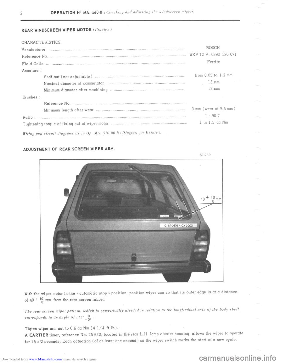
H/;r;,,p nj,d c;K,J;, djogmms 0.5 in O/j. .\1,2. i10-00 h Il)ing:rtirn Ior lirl0l~~ ) ADJUSTMENT OF REAR SCREEN WIPER ARM.
n
Tigtenwiperarm nut to0.6daNm (4 l/4 ft.lb).
A CARTIER
timer, reference No. 25 630, located in the IMT L.H. lamp cluster housihg, allows the wiper to operate
for 15 ? ‘2 seconds. Each actuation (of at least one second ) on the wiper switch marks the start of (I new cycle
Page 370 of 394
Downloaded from www.Manualslib.com manuals search engine Op. MA. 640-O 1 II CHECKING AND ADJUSTING :
1. Checking the operation of the air-conditioning :
Faulty operation may be due to the following
Insufficient quantity of R.12 fluid, caused by
improper filling 01 a leak.
Water in the system.
Insufficient quantity of fluid may be detected by examining the transparent index mark of the de-watering tank.
This lack of fluid would be shown up by the appearance of air-bubbles during operation.
The presence of water is shown up by the formation of a small quantity of ice near the pressure release valve
which causes irregular functioning of the system.
In both cases. the system must be drained. the circuits niust be put under vwzuum (to eliminate any trace of
water ). and refilled with R.12 fluid. 2. Corburation
: Adjusting the idling speeds (as soon as electric coolinq fans cut out )
a) Vc,hirlcs wi/hou/ loryue con wrtcr :
Engine idling speed 850 to 900 rpm ( compressor switched off )
Fast idling speed 1000 to 1050 rpm ( compressor in operation )
b) Vrhirles with torque co~twrt~~r
Engine idling speed 700 to 750 rpm ( compressor switched off )
Fast idling speed 725 to 775 rpm ( handbrake on, vehicle immobilised. one gear engaged, and compressor
switched off 1
The fast idling speed is adjustable by means of adjusting screw located on top of the vacuum capsule on the
cmburettor. NOTE
: In case the fast idle is impossible to obtain, the vacuum capsule may be moved ( slacken both fixing
screws on carburettor ). in order to reduce the clearance at the fixing point of the rod controlling the first
choke butterfly opening. 3. Adjusting the pulleys :
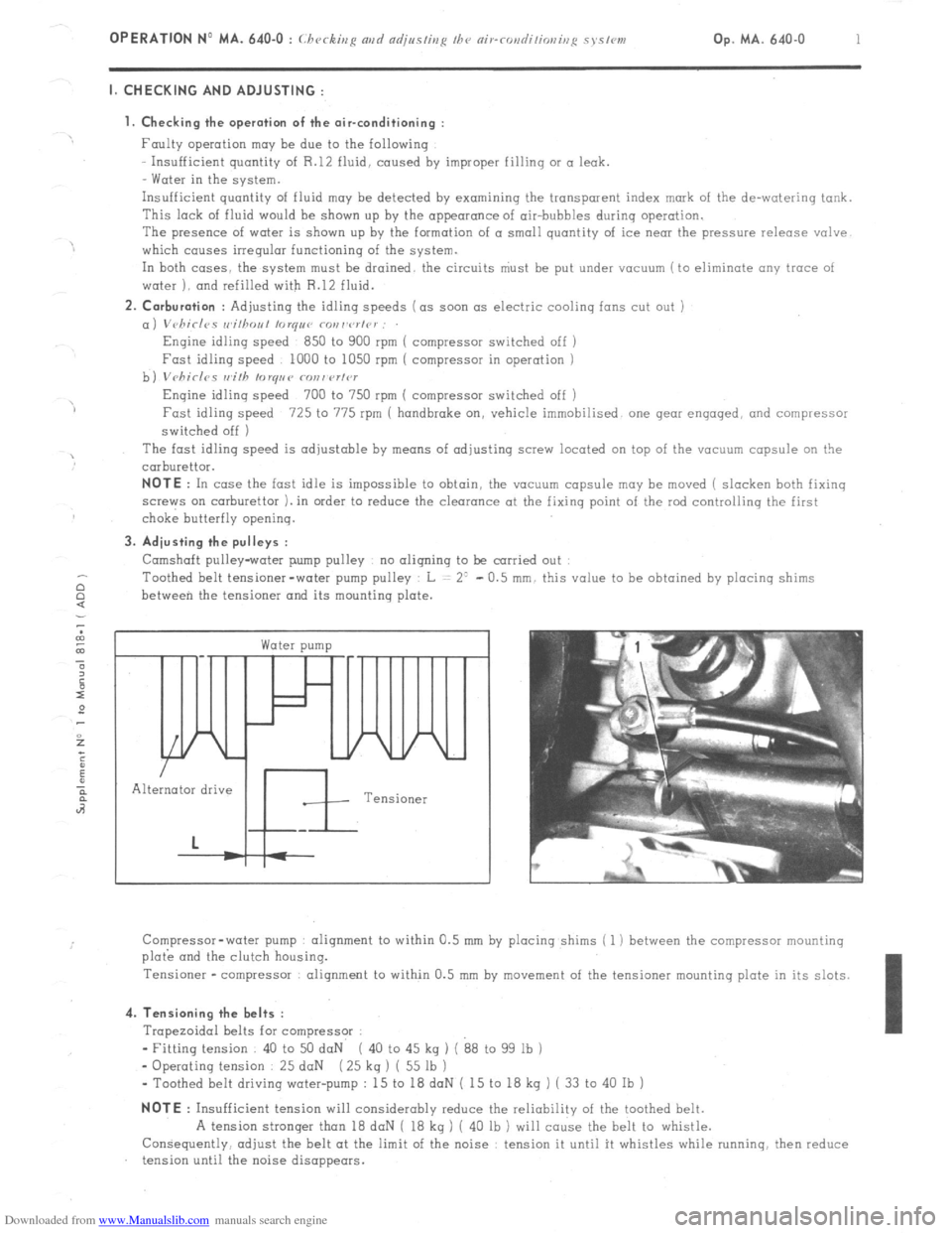
Camshaft pulley-water pump pulley no aligning to be carried out
Toothed belt tensioner-water pump pulley L = 2’ - 0.5 mm. this value to be obtained by placing shims
between the tensioner and its mounting plate. c
Water pump /
In
Alternator drive
Tensioner
Compressor-water pump alignment to within 0.5 mm by placing shims ( 1 ) between the compressor mounting
plo& and the clutch housing.
Tensioner -compressor alignment to within 0.5 mm by
movement of the tensioner mounting plate in its slots. 4. Tensioning the belts :
Trapezoidal belts for compressor :
- Fitting tension 40 to 50 daN ( 40 to 45 kg ) ( 88 to 99 lb )
- Operating tension 25 daN ( 25 kq ) ( 55 lb )
- Toothed belt driving water-pump : 15 to 18 doN ( 15 to 18 kg ) ( 33 to 40 Ib ) NOTE
: Insufficient tension will considerably reduce the reliability of the toothed belt.
A tension stronger than 18 daN ( 18 kg ) ( 40 lb ) will cause the belt to whistle.
Consequently, adjust the belt at the limit of the noise : tension it until it whistles while running. then reduce
tension until the noise disappears.
Page 371 of 394
Downloaded from www.Manualslib.com manuals search engine II. PRECAUTIONS TO BE TAKEN WHEN WORKING ON THE AIR-CONDITIONING SYSTEM
a) It is imperative to wear goggles
b ) Do not smoke R 12 fluid,in the presence of a flame turns into a toxic gas.
c) Never heat any section of the refrigerating system.
d) Never switch on the refrigerating system if both electric cooling fans are not connected
e ) Never check the compressor oil level without first having drained the refrigerating circuit.
f ) Never use any oil other than TOTAL (( LUNARIA 25 H, SUNISO No 5 or TEXACO CAPELLA (( E 1) grade 500
g ) Never use refrigerating fluid other than R.12.
NOTE Refrigerating fluid may- be sold under different names : FORANE (( 12 )), FLUGENE (( 12 ))! FREON ((12 ))
( the most important feature is the number (( 12 H which defines the fluid’s properties ).
IMPORTANT NOTES
A. The compressor
MUST NEVER b e switched on when the circuit has been drained of its refrigerating fluid.
during work ‘being carried out in the workshop. for example,. Indeed, in these conditions,
the compressor
would be functioning in air, and would deteriorate rapidly.
‘Consequently, in case of an exchange of compressor necessitating draining the system of its refrigerating
fluid, in a workshop not equipped with the necessary equipment for refilling ( SOGEV equipment )
IT IS
IMPERATIVE,
before driving the vehicle to another workshop equipped with the special equipment. to carry
out the following
- To leave the blanking plugs on the compressor. in order to avoid ingress of air ( the new compressor contains
refrigerating fluid ).
- To blank the intake and outlet hoses and to fix them tempororily.
- Todisconnect the supply lead to the electro-magnetic compressor clutch
( lead with white sleeve ).
NOTE : We remind you that if the circuit has been in contact with the atmosphere, it is necessary to replace
the de-watering tank, and the compressor oil.
B. Slight oil seepage is permissible at the front bearing of the air-conditioning compressor.
Compressors showing such a seepage, and being replaced OS a result, will not be accepted under warranty.
Ill. TIGHTENING TORQUES FOR THE UNIONS IN THE CIRCUIT :
( Oil the union threads with TOTAL LUNARIA 25 before fitting )
On the compressor Intake union : 5/8” 3.45 to 4.3,daNm ( 25 to 31 ft.lb )
Outlet union l/2”’ 2.9 to 3.75 daNm ( 21 to 27 ft.lb )
On the condenser Input union l/2” 4.85 to 5.5 daNm ( 35 to 39 3/4 ft.lb )
Output union : 3/ 8” 2.7 to 3.3 daNm ( 19 l/2 to 23 3/4 ft.lb )
On-de-watering tank : Unions : 3/8” 2.1 to 2.5daNm ( 15 l/4 to 18 ft.lb )
On : Input union evaporator : 3/8” 2.1 to 2.5 daNm ( 15 l/4 to 18 ft.lb )
Output union 5/8” 3.45 to 4.3 daNm ( 25 to 31 ft.lb )