Castor Citroen CX 1981 1.G Workshop Manual
[x] Cancel search | Manufacturer: CITROEN, Model Year: 1981, Model line: CX, Model: Citroen CX 1981 1.GPages: 394
Page 5 of 394
Downloaded from www.Manualslib.com manuals search engine .r.
-/1
LIST OF OPERATIONS
IN MANUAL 818-1
a CX Petrol )) 7,rhifles
--
-
f-7
i---- _--
-
Operation
number
MA. 330-00
MA . . 344-O
MA. 372-00
MA. 390-00
MA. 390-O
MA. 410-00
MA. 410-O
MA. 420-00
MA. 420-O
MA. 430-00
MA. 430-O
MA. 434-O
MA. ,440-00
MA. 440-O DESCRIPTION GEARBOX and GEARBOX CQNTROL
*O 4
Characteristics and special features of the gearbox
- Four-speed gearbox with pedal-operated clutch
- Gearbox.with torque converter
- Draining and refilling the gearbox and the torque converter
- Five-speed gearbox with pedal-operated clutch
Adjusting the gearbox control mechanism DRIVE SttiFTS
Characteristics and special features of the drive-shafts SOURCE AND RESERVE OF PRESSURE
Characteristics and special features of the source and reserve of pressure -
hydraulic system
Checking the hydraulic components on the vehicle FRONT AXLE
+O 7
Characteristics and special features of the front axle
Checking and adjusting the front axle :
- Checking the camber
- Checking and adjusting the castor angle
- Checking and adjusting the wheel alignment
- Checking and adjusting the steering geometry
- Checking the steering for straight line deviation (
whirfes cjq77ippcJrl with REAR AXLE
*O 8
Characteristics and special features of the rear axle
Checking and adjusting the rear axle SUSPENSION SYSTEM
I,0 9
Characteristics and special features of the suspension system
Checking and adjusting the suspension and its controls
Adjusting the anti-roll bar STEERING SYSTEM
*@
Characteristics and special features of the steering system
- Manual steering
- Power steering with powered return
Checking and adjusting the steering (see Op. MA. 410-O )
Ob
4
Ob 5
Ok 6
Ok 7
O+ 8
O1) 9
Page 232 of 394
Downloaded from www.Manualslib.com manuals search engine FRONT AXLE
OPERATION No MA. 410-00 : Charnctvristics arid S(ICJCI’O~ /‘rattrres o,i the front as/e unit Op. MA. 410-00 1
t
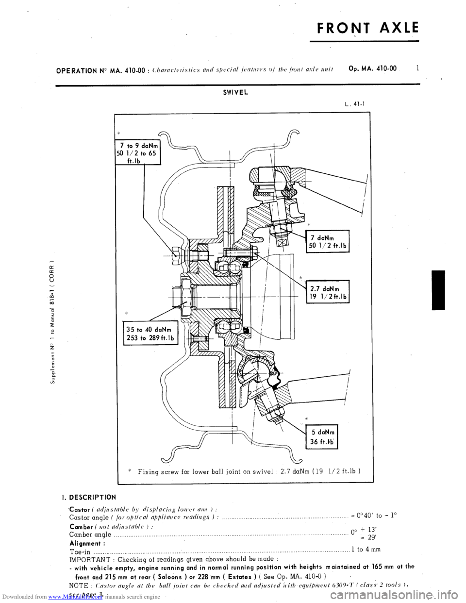
SWIVEL
L. 41-l
2.7 daNm
19 1/2ft.lb
‘* Fixing screw for lower ball joint on swivel 2.7 daNm (19 l/2 ft.lb )
I. DESCRIPTION
‘Castor
( adjustable by displacirlg 1011’er am ) :
Castor angle ( for optical appliatjce readings ) : _.,,....._..._,......,,,,,,.......,.,........,,,.,......,,............ - 0’40’
to - lo
Camber ( ttot adiastable ) :
Camber angle ,,.,,,.,,,..._,,,__.....,...,,.........,,.,.......................................................................... . . . . . 00 + 13’
- 29’
Alignment :
Toe-in ,.........._.__...,.,..,.,,.,,,,,.........,,,,.,......................,....................................................................... 1 to 4
mm
IMPORTANT : Checking of readings given above should be made :
- with vehicle empty, engine running and in normal running position with heights maintained at 165 mm at the
front and 215 mm at rear ( Saloons ) or 228.mm ( Estates ) ( See
Op. MA. 410-O ) ~
NOTE : Castor allgle at the ball joint cau be checked aud adjusted ic’itb equipmcwt 6309.7‘ f class- 2 tools J,
see page 3.
Page 234 of 394
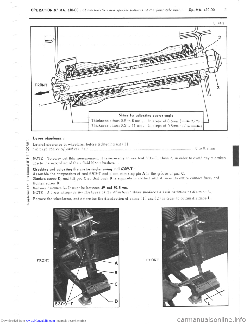
Downloaded from www.Manualslib.com manuals search engine Shims for adjusting castor angle
Thickness from 0.5 to 6 mm ,
in steps of 0.5mm (- - Lower wheelorms :
E Lateral cleoronce of wheelarm. before tightening nut (3 1
z ( fbmugh rhoicr o/ wnshr~r I I u I ,..................,.,............................,..,..,.,........................,....,...... 0 to 0.9 mm
2 NOTE To carry out this measurement, it is necessary to use tool 6312-T. class 2. in order to ovoid any mistakes
t due to the expanding of the G fluid-bloc n bushes. g Checking and adjusting the castor angle, using tool 6309-T :
s Assemble the components of tool 6309-T and place checking pin A in the groove of pod C.
2 Slacken screw D,
and tilt pad C so that bush B is squarely in contact with it, over its entire contact face. and
f tighten screw D.
; Measure distance L. It must be between 49 and 50.5 mm.
: NOTE A I mm rhaug~~ ia the Ihirknrss o//he adjr~s/mw/ shims produc-~s a Imm r~ariatim oi rlislmc~ L.
Remove the wheelarms, and determine the distribution of shims ( 1) and ( 2 ) in order to obtain distance L.
FRONT FRON T
Page 239 of 394
Downloaded from www.Manualslib.com manuals search engine III. CHECKING THE CAMBER ANGLE
NOTE : The camber angle is not adjustable.
1. Prepare vehicle and set in position f src chapfrrs
I and 2 ).
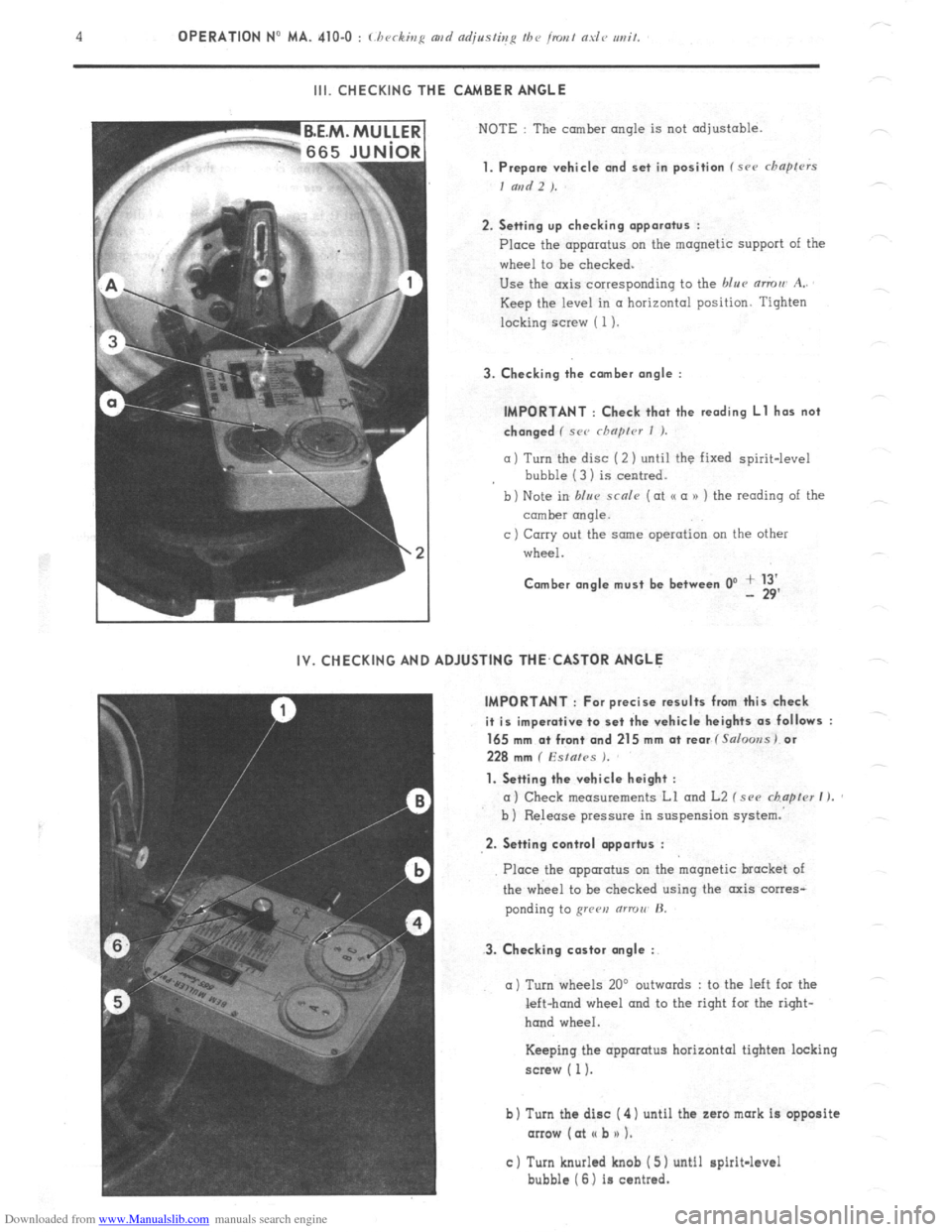
2. Setting up checking apparatus :
Place the apparatus on the magnetic support of the
wheel to be checked.
Use the axis corresponding to the blue mmu A..
Keep the level in a horizontal position. Tighten
locking screw ( 1).
3. Checking the comber angle :
IMPORTANT : Check that the reading Ll has not
changed ( SC<’ rhnprcr I ).
a) Turn the disc (2 ) until the fixed spirit-level
bubble (3 1 is centred.
b) Note in blur scnle (at o a n ) the reading of the
comber rmqle.
c ) Carry out the same operation on the other
wheel.
Comber angle must be between 0’ + 13’ - 29’
IV. CHECKING AND ADJUSTING THE,CASTOR ANGLE
IMPORTANT : For precise results from this check
it is imperative to set the vehicle heights as follows :
165 mm a+ front and 215 mm at rear f Salooss) or
228 mm ( Esfafes ).
1. Setting the vehicle height :
a) Check measurements Ll and L2 f see chapter I ).
b ) Release pressure in suspension system.
2. Setting control opportus :
3. Checking castor angle :
Place the apparatus on the magnetic bracket of
the wheel to be checked using the axis corres-
ponding to grren (ITTOII’ H.
a) Turn wheels 20’ outwards : to the left for the
left-hand wheel and to the right for the right-
hand wheel.
Keeping the apparatus horizontal tighten locking
screw ( 1).
b) Turn the disc ( 4) until the zaro mark is opposite
arrow (at I( b n 1.
c) Turn knurled knob ( 5) until spirit-level
bubble (6) is centred.
Page 240 of 394
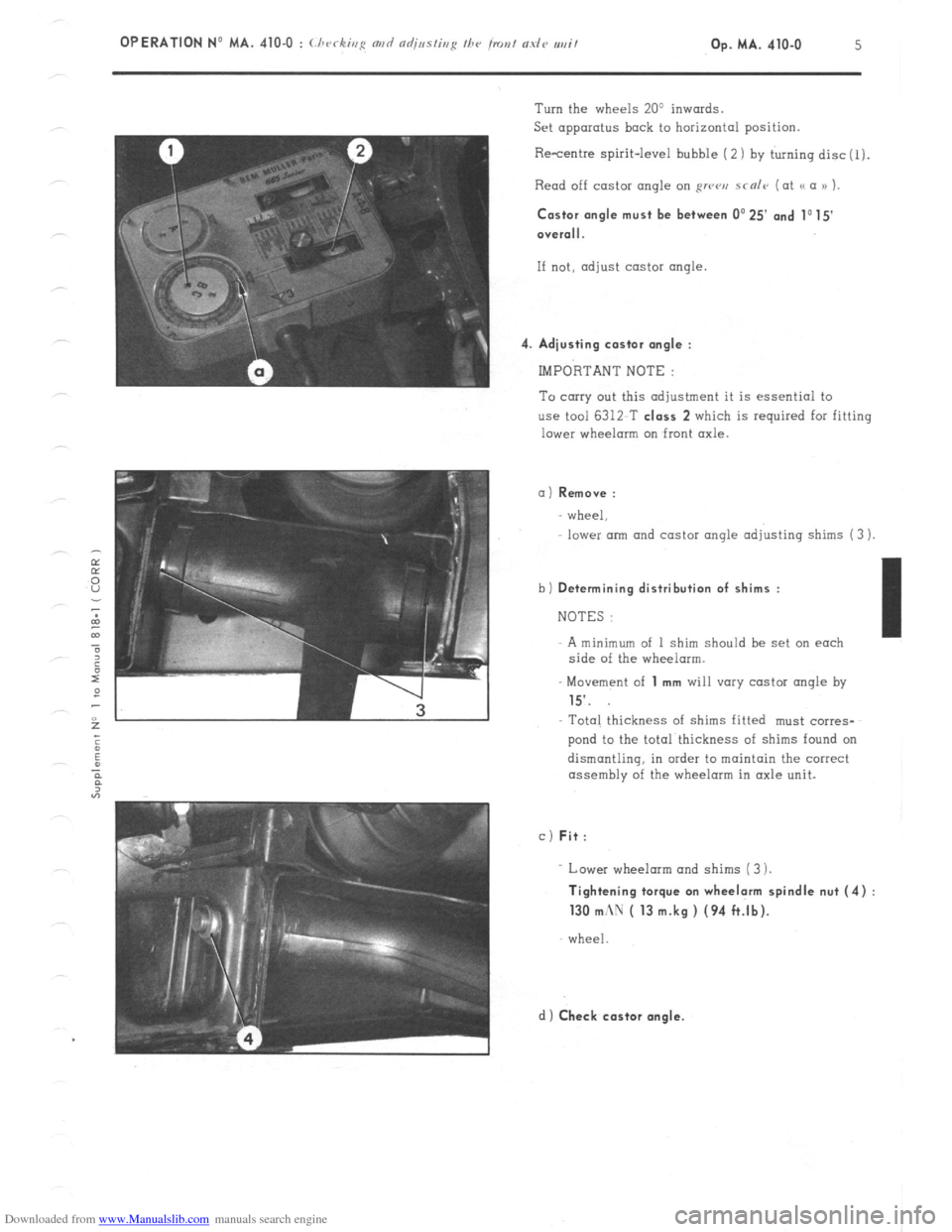
Downloaded from www.Manualslib.com manuals search engine 4 Turn the wheels 20’ inwards.
Set apparatus back to horizontal position.
Resentre spirit-level bubble ( 2) by turning disc(l).
Read off castor angle on RWCJ,J scnlr (at a a )) ).
Castor angle must be
between 0’25’ and 1015
O”erall.
If not, adjust castor angle
Adiusting castor angle :
IMPORTANT NOTE :
To carry out this adjustment it is essential to
use tool 6312 T class 2 which is required for fitting
lower wheelorm on front axle.
a) Remove :
wheel,
lower arm and castor angle adjusting shims (3 )
b)
Determining distribution of shims :
NOTES :
A minimum of 1 shim should be set on each
side of the wheelarm.
- Movement of
1 mm will vary castor angle by
15’.
Total thickness of shims fitted must corres-
pond to the total thickness of shims found on
dismantling, in order to maintain the correct
assembly of the wheelarm in axle unit.
c) Fit:
Lower wheelarm and shims (3 ).
Tightening torque on wheelarm spindle nut (4)
130 mc\U ( 13 m.kg ) (94 ft.lb).
wheel
d) Check castor angle.