diagram Citroen CX 1981 1.G Workshop Manual
[x] Cancel search | Manufacturer: CITROEN, Model Year: 1981, Model line: CX, Model: Citroen CX 1981 1.GPages: 394
Page 4 of 394
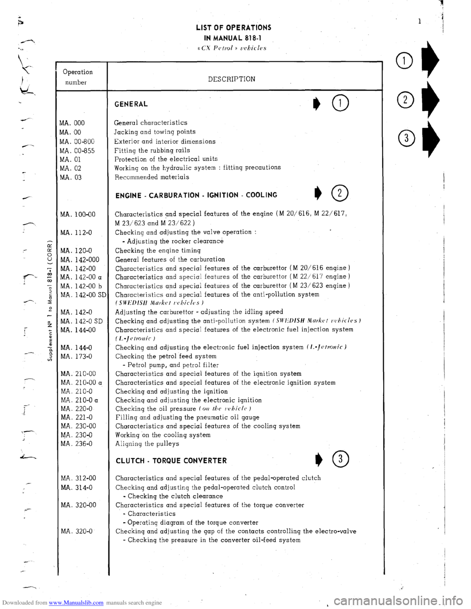
Downloaded from www.Manualslib.com manuals search engine Operation
number
VIA. 000
VIA. 00
VIA. 00-600
vlA. 00-655
VIA. 01
WA. 02
MA. 03
MA. 100-00
MA. 112-O
MA. 120-O
MA. 142-000
MA. 142-00
MA. 142-00 a
MA. 142-00 b
MA. 142-00 SI
MA. 142-O
MA. 142-O SD
MA. 144-00
MA. 144-O
MA. 173-O
MA. 210-00
MA. 210-00 a
MA. 210-O
MA. 210-O a
MA. 220-O
MA. 221-O
MA. 230-00
MA. 230-O
MA. 236-O
MA. 312-00
MA. 314-O
MA. 320-00
MA. 320-O LIST OF OPERATIONS
IN MANUAL 818-l
cc CX Petrol )) uehicles
DESCRIPTION GENERAL
General characteristics
Jacking and towing points
Exterior and interior dimensions
Fitting the rubbing rails
Protection of the electrical units
Working on the hydraulic system : fitting precautions
Recommended materials ENGINE - CA,RBURATlON - IGNITION - COOLING
+O 2
Characteristics and special features of the engine (M 20/616, M 22/ 617,
M 23/623 and M 23/622 )
Checking and adjusting the valve operation :
- Adjusting the rocker clearance
Checking the engine timing
General features of the carburation
Characteristics and special features of the carburettor (M 20/616 engine )
Characteristics and special features of the carburettor ( M 22/617 engine )
Characteristics and special features of the carburettor ( M 23/ 623 engine )
Characteristics and special features of the anti-pollution system
I SWEDISH Jlurket r,c~kicles )
Adjusting the carburettor - adjusting the idling speed
Checking and adjusting the anti-pollution system
(SIVI:‘DfSH Mdrkct rvhicles J
Characteristics and special features of the electronic fuel injection system
(L.~etKJnic )
Checking and adjusting the electronic fuel injection system (1..Jetrolzic)
Checking the petrol feed system
- Petrol pump, and petrol filter
Characteristics and special features of the ignition system
Characteristics and special features of the electronic ignition system
Checking and adjusting the ignition
Checkinq and adjusting the electronic ignition
Checking the oil pressure (on
the rvhicle )
Filling and adjusting the pneumatic oil gauge
Characteristics and special features of the cooling system
Working on the cooling system
Aligning the pulleys CLUTCH - TORQUE CONVERTER
*O 3
Characteristics and special features of the pedal-operated clutch
Checking and adjusting the pedal-operated clutch control
- Checking the clutch clearance
Characteristics and special features of the torque converter
- Characteristics
- Operating diagram of the torque converter
Checking and adjusting the gap of the contacts controlling the electro-valve
- Checking the pressure in the converter oil-feed system
Page 6 of 394
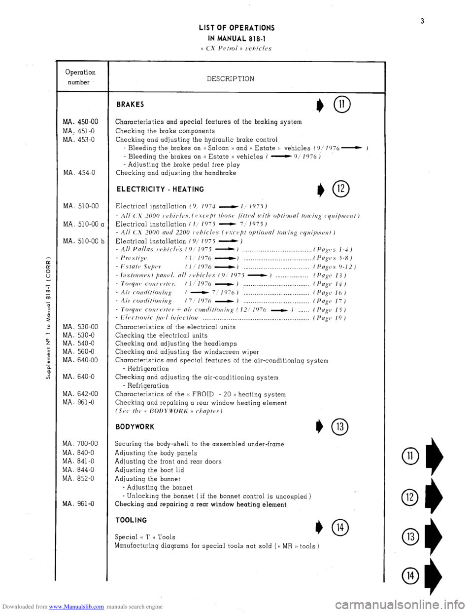
Downloaded from www.Manualslib.com manuals search engine LIST OF OPERATIONS
IN MANUAL 818-l
Operation
number
MA. 450-00
MA,. 451-O
MA. 453-O
MA. 454-O
MA. 510-00
MA. 51 O-00 a
MA. 510-00 b
MA. 530-00
MA. 530-O
MA. 540-O
MA. 560-O
MA. 640-00
MA. 640-O
MA. 642-00
MA. 961-O
MA. 700-00
MA. 840-O
MA. 841-O
MA. 844-O
MA. 852-O
MA. 961-O DESCRIPTION BRAKES
Characteristics and special features of the braking system
Checking the brake components
Checking and adjusting the hydraulic brake control
- Bleeding the brakes on (( Saloon )) and (( Estate H vehicles (‘)/ lO76- )
- Bleeding the’brakes on (( Estate )) vehicles (
-911976)
- Adjusting the brake pedal free play
Checking and adjusting the handbrake ELECTRICITY - HEATING
I,0 12
Electrical installation ( 9, 1074 -1,1975)
- All C..X 2000 t’cJllicl0.Y. ( cJ.vc-u[)t those 1.ittcd with optimnl towitzg (,rjriiptueflt )
Electrical installation ( I/ 1975 - 711975)
- All <.X 2000 nrtcl 2200 I c>hiclcs (esrept optiwnl towing ccjrli/mv~~t )
Electrical installation ( c)/ 1 !J7 5 - J
- All Pnllas whirlck (Of 1975 :.I __._._.___............................ (Pfiges j-4)
- Prc,.s tige (I 1976 ----tJ . . . . . . . . . . . . . . . . .._.................. (Pngc~s 5-8)
- Estntc SIIpw IIf 1976 -1 . . . . . . . . . . . . . . . . . . . . . . . . . . . . . . . . . . . . (Pugc,s 9-12 )
- I~~strriv~cut pajf~,I. nil r~c~hicles (9!’ 1975 - ) . ( Page 13 )
- Tvrqrl~~ COIlI erter. (l/l976 - ) . . . . . . . . . . . . . . . . . . . . . . . . . . . . . . . . . . . . ( I’ogc, 14 )
- Air rotiditioffir~g ( - 7:
1076 ) : . . . (PcIgc- 16)
- Air covditiorli,lg (7! 1976 - J . . . .
- ‘l’orytrc~ coilr’f’rter + air contlitiotfirfg ( 12/ 1976 - )
- I?Iect~~r~ic j&l
if~iectiov . . . . . . . . . . . . . . . . . . . . . . . . . . . . . . . . . . . . . . . . . . . . . . . . . .
Characteristics of the electrical units
Checking the electrical units
Checking and adjusting the headlamps
Checking and adjusting the windscreen wiper
Pngc 17)
Pogc 15 )
Pup 19)
Characteristics and special features of the air-conditioning system
- Refrigeration
Checking and adjusting the air-conditioning system
- Refrigeration
Characteristics of the (( FROID - 20 )) heating system
Checking and repairing a rear window heating element
(Set, r/JP cc I~OI~~‘WOKK 1) rilnptc~rj
BODYWORK
*0 13
Securing the body-shell to the assembled under-frame
Adjusting the body panels
Adjusting the front and rear doors
Adjusting the boot lid
Adjusting the bonnet
- Adjusting the bonnet
- Unlocking the bonnet ( if the bonnet control is uncoupled )
Checking and repairing a rear window heating element TOOLING
Special (( T )) Tools *O 14
Manufacturing diagrams for special tools not sold (cc MR )) tools )
O1)
11
Ol) 12
Ok 13
O1) 14
Page 40 of 394
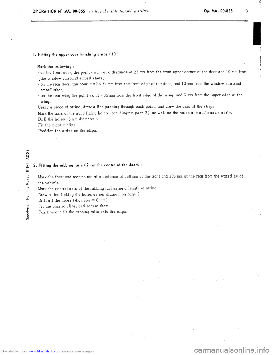
Downloaded from www.Manualslib.com manuals search engine OPERATION No MA. 00-855 : Fitting the side finishing strips. Op. MA. 00-855 3
1. Fitting the upper door finishing strips (1 ) :
/
Mark the following : I
- on the front door, the point u a 1 1) at a distance of 23 mm from the front upper corner of the door and 10 mm from I
. the window surround embellishers,
- on the rear door, the point (( a 7 )) 31 mm from the front edge of the door, and 10 mm from the window surround
embellisher,
- on the rear wing the point u a 13 1) 35 mm from the front edge of the wing, and 6 mm from the upper edge of the
wing.
Using a piece of string, draw a line passing through each point, and draw the axis of the strips.
Mark the axis of the strip fixing holes (see diagram page 2 ), as well as the holes at (( a 17 )) and CC a 18 )).
Drill the holes ( 5 mm diameter ).
Fit the plastic clips.
Position the strips on the clips.
2 2. Fitting the rubbing roils (2) ot the centre of the doors :
0
2 Mark the front and rear points at a distance of 260 mm at the front and 208 mm at the rear from the waistline of
2 the vehicle.
2
Mark the central axis of the rubbing rail using a length of string.
2 Draw a line linking the holes as per diagram on page 2.
Drill all the holes (diameter = 8 mm).
s
5 Fit the plastic clips, and secure them.
a Position and fit the rubbing rails onto the clips.
a
2
Page 65 of 394
Downloaded from www.Manualslib.com manuals search engine d) Valve springs :
The inlet and exhaust valve springs are identical.
Characteristics :
- Diameter of wire : . . . . . . . . . . . . . . . . . . . . . . . . . . . . . . . . . . . . . . . . . . . . . . . . . . . . . . . . . . . . . . . . . . . . . . . . . . . . . . . . . . . 4.6 + 0.02 mm
Interior diameter : . . . . . . . . . . . . . . . . . . . . . . . . . . . . . . . . . . . . . . . . . . . . . . . . . . . . . . . . . . 25 2 0.2 mm
- Length of spring under load : . . . . . . . . . . . . . . . . . . . . . . . . . . . . . . . . . . . . . . . . . . . . . . . . .
1 39mm(load=m40t2,8kg)
30.6 mm ( load = 84 ~‘1.8 kg )
Coating : ._._................................................................................................ Red or blue varnish
e) Upper spring cups : Identical inlet and exhaust.
f ) Retaining clips : Identical inlet and exhaust
6. Timing :
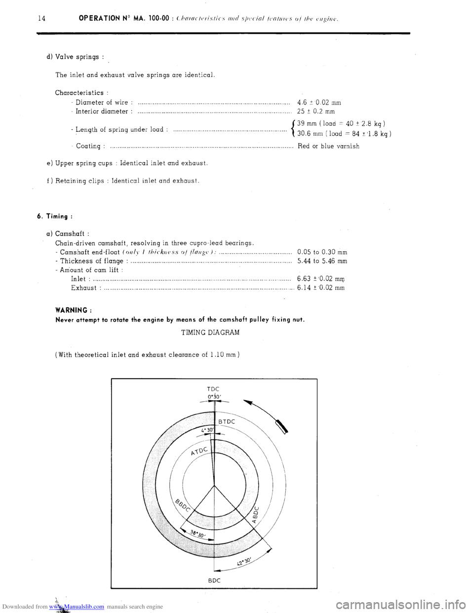
a) Camshaft :
Chain-driven camshaft, resolving in three cupro -lead bearings.
- Camshaft end-float (a,//>~ I /hi<-krlc~ss a,/ !/o,/s(, I: 0.05 to 0.30 mm
- Thickness of flange : . . . . . . . . . . . . . . . . . . . . . . . . . . . . . . . . . . . . . . . . . . . . . . . . . . . . . . . . . . . . . . . . . 5.44 to 5.46 mm
- Amount of cam lift :
Inlet : . . . . . . . . . . . . . . . . . . . . . . . . . . . . . . . . . . . . . . . . . . . . . . . . . . . . ..__.._..._ _.;._.; .._...._ ..__.___.., 6.63
2’0.02 mm
Exhaust : ___._._..._.........................................................................................,... 6.14 + ‘0.02 mm
WARNING :
Never attempt to rotate the engine by means of the camshaft pulley fixing nut.
TIMING DIAGRAM
(With theoretical inlet and exhaust clearance of 1 .lO mm )
Page 76 of 394
Downloaded from www.Manualslib.com manuals search engine OPERATION N” MA. 142.000 : c ,, P)C rni ,t n i,,, <‘ 0, I/?< < rirheri,/irin.
Op. MA. 142.000
5
2
:
m
2
-
b E
*
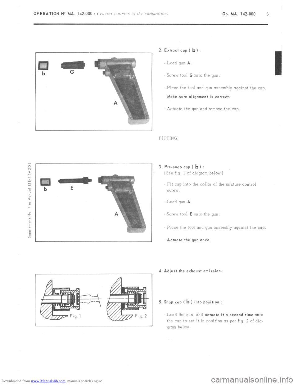
2. Extract cop ( ly) :
- Load gun A.
Screw tool G onto the gun.
Place the tool and gun assembly against the cop
Make sure alignment is correct.
Actuate the gun and remove the cop.
FITTING.
3.
~re-rno~ cap ( b) :
(See fig. I of diagram below )
Fit cap into the collar of the mixture control
screw.
Load qun
A.
Screw tool E onto the wn
Place the tool and gun assembly against the cop
’ 1 1 Actuate the gun once.
4. Adjust the exhaust emission.
I
5. ~nop cop (
b ) into position :
Load the gun. and (~ctuote it o second time onto
the cop to set it in position as per fig. 2 of dio-
gram below.
Page 87 of 394
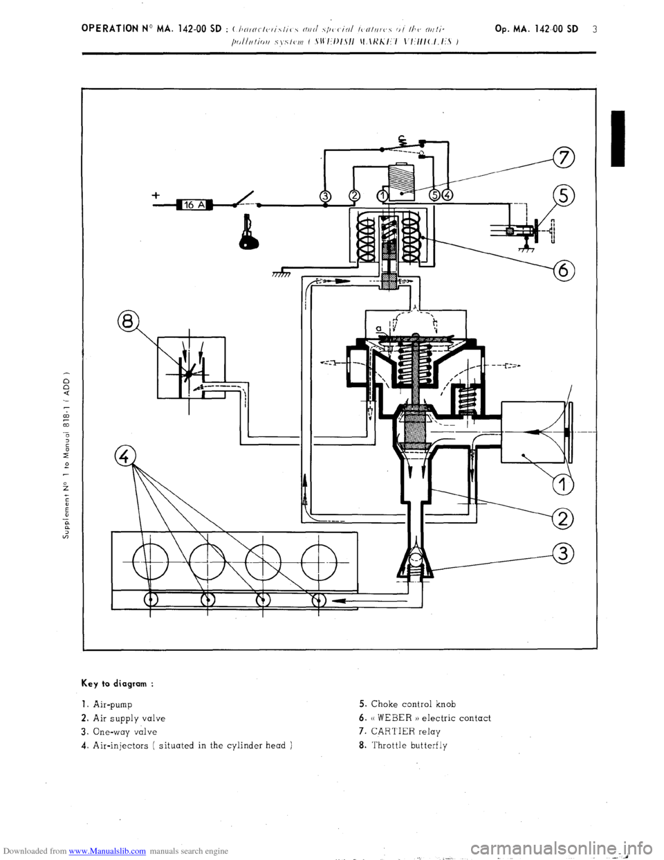
Downloaded from www.Manualslib.com manuals search engine Key to diagram :
1.
Air-pump 5. Choke control knob
2. Air supply valve 6. (( WEBER )) electric contact
3. One-way valve 7. CARTIER relay
4. Air-injectors ( situated in the cylinder head ) 8. Throttle butterfly
Page 115 of 394
Downloaded from www.Manualslib.com manuals search engine CIRCUIT DIAGRAM
L.Sl-19
I III I
I
--_
------
-- ---- 1 r---7
2, 0 ;,”
1 ---J
::- ----
---- r---~
“‘i
Page 131 of 394
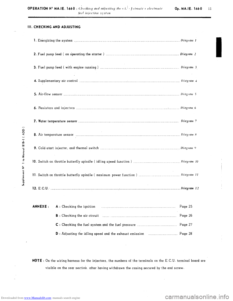
Downloaded from www.Manualslib.com manuals search engine Ill. CHECKING AND ADJUSTING
1
. Energizing the system ..................................................................................................................
2. ,Fuel pump feed ( on operating the starter ) .............................................................................
3. Fuel pump feed ( with engine running ) ...................................................................................
4. Supplementary air control ...........................................................................................................
5. Air-flow sensor ............................................................................................................................
6. Resistors and injectors ................................................................................................... . ........
7. Water temperature sensor ............................................................................................................ .
Dingram 7
8. Air temperature sensor ...............................................................................................................
9. Cold-start injector, and thermal switch ...................................................................................
10. Switch on throttle butterfly spindle ( idling speed function ) ............................................ 11
Switch on throttle butterfly spindle ( maximum power function ) ...................................... 12.
E.C.U: ......................................................................... ..~ ............................................................... . . Diagram 1 I ANNEXE : A
: Checking the ignition .................................................................................. Page 25 B
: Checking the air circuit ................................................................................ Page 26
C : Checking the fuel system and the fuel pressure ........................................... Page 27 D
: Adjusting the idling speed and the exhaust emission .............................. Page 28 NOTE
: On the wiring harness for the injectors, the numbers of the terminals on the E.C.U. terminal board are
visible on the rear section. after having withdrawn the casing secured by the end screw.
Page 132 of 394
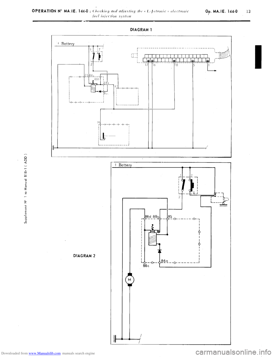
Downloaded from www.Manualslib.com manuals search engine 1. Energizing the system : ( DIAGRAM 1 )
_ Disconnect the E.C U
- Switch the ignition on
Using a voltmeter. ensure that each point in
dingrm 1 is effectively energised. after having tested the
earthing. If not, switch off the ignition. and test the circuit using a battery operated ohmmeter. With the
voltmeter connected between terminals ( 1 ) and ( 5) of the E. C.U., operate the starter the voltmeter must
register the ignition impulses If it does not. check the ignition
( ANNEXE A ).
2. Fuel pump feed ( on operating the starter ) ( DIAGRAM 2 )
- Disconnect the E C.U.
- Switch on the ignition
- On operating the starter. the fuel pump (
secureri rrt/rler the I c~hiclc’. uoor IIJO K. ti. ronr (, l~eol I must be
heard to operate by someone standing close by
If not switch off the ignition, and test the circuit using a battery operated ohmmeter.
The resistance between terminal (( 88 d H of the relay assembly ( c~r~tler 111~
L,H. honr/llor)~p ) and earth
must be 1 Q approx-
Make sure the petrol pump is properly earthed.
Page 133 of 394
Downloaded from www.Manualslib.com manuals search engine f
E
E
a
a
2 DIAGRAM 1
I t
5 E 0
t-
DIAGRAM 2 /
-
t Battery +-----
0-1