timing Citroen CX 1981 1.G Workshop Manual
[x] Cancel search | Manufacturer: CITROEN, Model Year: 1981, Model line: CX, Model: Citroen CX 1981 1.GPages: 394
Page 4 of 394
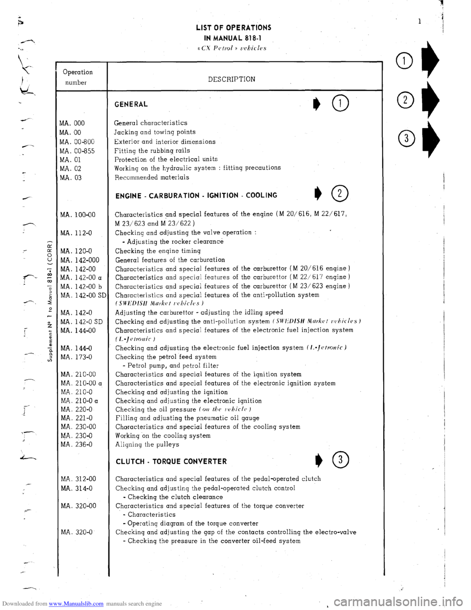
Downloaded from www.Manualslib.com manuals search engine Operation
number
VIA. 000
VIA. 00
VIA. 00-600
vlA. 00-655
VIA. 01
WA. 02
MA. 03
MA. 100-00
MA. 112-O
MA. 120-O
MA. 142-000
MA. 142-00
MA. 142-00 a
MA. 142-00 b
MA. 142-00 SI
MA. 142-O
MA. 142-O SD
MA. 144-00
MA. 144-O
MA. 173-O
MA. 210-00
MA. 210-00 a
MA. 210-O
MA. 210-O a
MA. 220-O
MA. 221-O
MA. 230-00
MA. 230-O
MA. 236-O
MA. 312-00
MA. 314-O
MA. 320-00
MA. 320-O LIST OF OPERATIONS
IN MANUAL 818-l
cc CX Petrol )) uehicles
DESCRIPTION GENERAL
General characteristics
Jacking and towing points
Exterior and interior dimensions
Fitting the rubbing rails
Protection of the electrical units
Working on the hydraulic system : fitting precautions
Recommended materials ENGINE - CA,RBURATlON - IGNITION - COOLING
+O 2
Characteristics and special features of the engine (M 20/616, M 22/ 617,
M 23/623 and M 23/622 )
Checking and adjusting the valve operation :
- Adjusting the rocker clearance
Checking the engine timing
General features of the carburation
Characteristics and special features of the carburettor (M 20/616 engine )
Characteristics and special features of the carburettor ( M 22/617 engine )
Characteristics and special features of the carburettor ( M 23/ 623 engine )
Characteristics and special features of the anti-pollution system
I SWEDISH Jlurket r,c~kicles )
Adjusting the carburettor - adjusting the idling speed
Checking and adjusting the anti-pollution system
(SIVI:‘DfSH Mdrkct rvhicles J
Characteristics and special features of the electronic fuel injection system
(L.~etKJnic )
Checking and adjusting the electronic fuel injection system (1..Jetrolzic)
Checking the petrol feed system
- Petrol pump, and petrol filter
Characteristics and special features of the ignition system
Characteristics and special features of the electronic ignition system
Checking and adjusting the ignition
Checkinq and adjusting the electronic ignition
Checking the oil pressure (on
the rvhicle )
Filling and adjusting the pneumatic oil gauge
Characteristics and special features of the cooling system
Working on the cooling system
Aligning the pulleys CLUTCH - TORQUE CONVERTER
*O 3
Characteristics and special features of the pedal-operated clutch
Checking and adjusting the pedal-operated clutch control
- Checking the clutch clearance
Characteristics and special features of the torque converter
- Characteristics
- Operating diagram of the torque converter
Checking and adjusting the gap of the contacts controlling the electro-valve
- Checking the pressure in the converter oil-feed system
Page 52 of 394
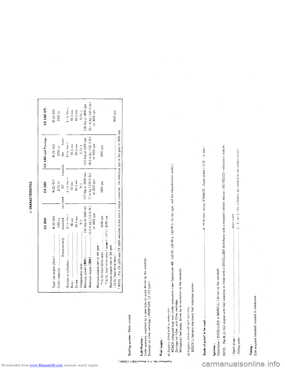
Downloaded from www.Manualslib.com manuals search engine I. CHARACTERISTICS
:
0
u
5 Cooling system : Water cooled.
z
T cx 2000 cx 2200 CX 2400 and Prestige
CX 2400 GTI
- Type ( on engine p’late ) : _..._................... M 20/616 M 22/617 M 23/ 623
M 23/622
Cubic capacity : . . .._......_...............
1985 cc 2175 cc 2350 cc 2350 cc
Transversely mounted, inclined
300 towards the front
Number of cylinders : _........................... 4 (iI/ linr, J 4 Iin linr,)
4 (irr /iUP J 4 f in lin i’ ,
Bore : 86 mm 90 mm 93.5 mm 93.5 mm
- Stroke : .,.,,_,.,.,....____.,.. .._._.....................
85.5 mm 85.5 mm 85.5 mm
85.5 mm
Compression ratio :
9/I 9/l 8.7511 8.7511
Maximum power ( DIN ) : . . . .._................... 102 bhp at 5500 rpm 112 bhp at 5500 rpm 115 bhp ot 5500 rpm
128 bhp at 4800 rpm
Maximum torque (DIN)
: . . 15.5 m.kg (112 ft.Ib ) 17 m.kq (123 ft.Ib) 18.2 m.kg ( 132 ft.Ib)
20.1 mkq (145 ft.Ib)
at 3000 rpm at 3500 rpm at 3000 rpm
at 3600 rpm
Maximum engine rpm in 4th gear :
* 13/62 final drive rtrtio :
5600 rpm 5800 rpm 5900 rpm
*14/61 final drive ratio ( -1 1’175 J 4600 rpm
Maximum engine rpm in 5th gear
(
13,‘62 final drive ratio ) : ,._............,..,........,....,.,........,..,.,..... .._.........,................ .._..._...................
5600 rpm
* NOTE : For CX 2200 and CX 2400 vehicles fitted with a torque converter, the maximum rpm in 3rd gear is 5600 rpm.
: Lubrification :
i
Under pressure, supplied by o gear-type oil-pump driven by the camshaft.
2
External oil filter cartridge ( PURFLUX, LS 105 type ).
d
z
;
i Fuel supply :
a
i a) Engines fitted u~ifh a rnrbuwffor
WEBER compound-type twin choke carburettor (s.ee Operations MA. 142-00, 142-00 a, 142-00 b far the type, and the identification marks )
Dry-type air filter, with filter cartridge.
Mechanical fuel pump, driven by on eccentric on the camshaft.
b) i?ugi,jes ji/f.rd II ith /LIP/ iniPr/ioo :
BOSCH L-Jetronic electronic fuel injection system
Grade of pet,ol to be used : > ._,,,,.,_.._,,,,,.,......... . .._...o....._............................................. K.
99 Orrani ralrrig (FRANCE : Super grade ) (U.K. : 4-star )
Ignition :
Distributor ( DUCELLIER or MARELLI ) driven by the camshaft.
NOTE : The M 23/622 engine with fuel injection is fitted with (I DUCELLIER distributor with a magnetic sensor, and an u AC-DELCO /a electronic module.
- Spark pluqs : .................................................................................................................................... shorf warh
Firing o&r : .................................................................................................................................... 1 - 3 - 4 - 2 f tbu cylinders ale INR&Cd 011 the roc6w COI rr,
Timing :
Side mounted camshaft located in crankcase.
Page 56 of 394
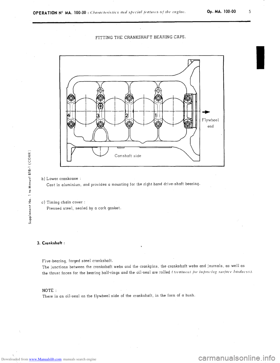
Downloaded from www.Manualslib.com manuals search engine FITTING THE CRANKSHAFT BEARING CAPS
Camshaft side Camshaft side ‘W
Flywheel
end
b) Lower crankcase :
Cast in aluminium, and provides a mounting for the right~hand drive-shaft bearing.
c) Timing chain cover :
Pressed steel, sealed by a cork gasket. 3. Crankshaft :
Five-bearing, forged steel crankshaft.
The junctions between the crankshaft webs and the crankpins, the crankshaft webs and journals, as well as
the thrust faces for the bearing half-rings and the oil-seal are rolled
(Iwalmc,r/l i~r iw/lro/~ir/g sur]ncc~ horr/r/c,ssI
NOTE :
There is an oil-seal on the flywheel side of the crankshaft, in the form of a bush.
Page 65 of 394
Downloaded from www.Manualslib.com manuals search engine d) Valve springs :
The inlet and exhaust valve springs are identical.
Characteristics :
- Diameter of wire : . . . . . . . . . . . . . . . . . . . . . . . . . . . . . . . . . . . . . . . . . . . . . . . . . . . . . . . . . . . . . . . . . . . . . . . . . . . . . . . . . . . 4.6 + 0.02 mm
Interior diameter : . . . . . . . . . . . . . . . . . . . . . . . . . . . . . . . . . . . . . . . . . . . . . . . . . . . . . . . . . . 25 2 0.2 mm
- Length of spring under load : . . . . . . . . . . . . . . . . . . . . . . . . . . . . . . . . . . . . . . . . . . . . . . . . .
1 39mm(load=m40t2,8kg)
30.6 mm ( load = 84 ~‘1.8 kg )
Coating : ._._................................................................................................ Red or blue varnish
e) Upper spring cups : Identical inlet and exhaust.
f ) Retaining clips : Identical inlet and exhaust
6. Timing :
a) Camshaft :
Chain-driven camshaft, resolving in three cupro -lead bearings.
- Camshaft end-float (a,//>~ I /hi<-krlc~ss a,/ !/o,/s(, I: 0.05 to 0.30 mm
- Thickness of flange : . . . . . . . . . . . . . . . . . . . . . . . . . . . . . . . . . . . . . . . . . . . . . . . . . . . . . . . . . . . . . . . . . 5.44 to 5.46 mm
- Amount of cam lift :
Inlet : . . . . . . . . . . . . . . . . . . . . . . . . . . . . . . . . . . . . . . . . . . . . . . . . . . . . ..__.._..._ _.;._.; .._...._ ..__.___.., 6.63
2’0.02 mm
Exhaust : ___._._..._.........................................................................................,... 6.14 + ‘0.02 mm
WARNING :
Never attempt to rotate the engine by means of the camshaft pulley fixing nut.
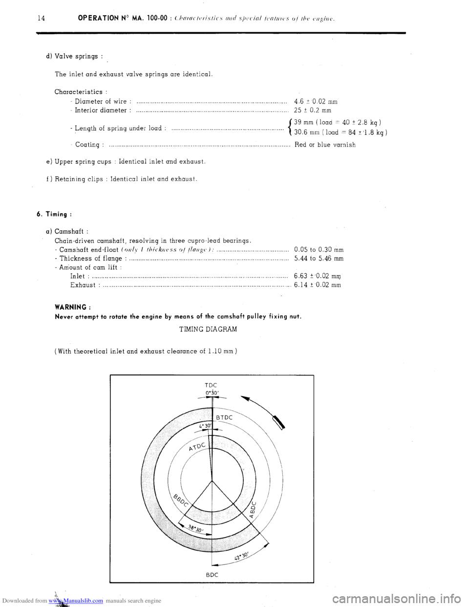
TIMING DIAGRAM
(With theoretical inlet and exhaust clearance of 1 .lO mm )
Page 66 of 394
Downloaded from www.Manualslib.com manuals search engine OPERATION No MA. 100-00 : Characteristics and special features of the engine. Op. MA. 100.00 15
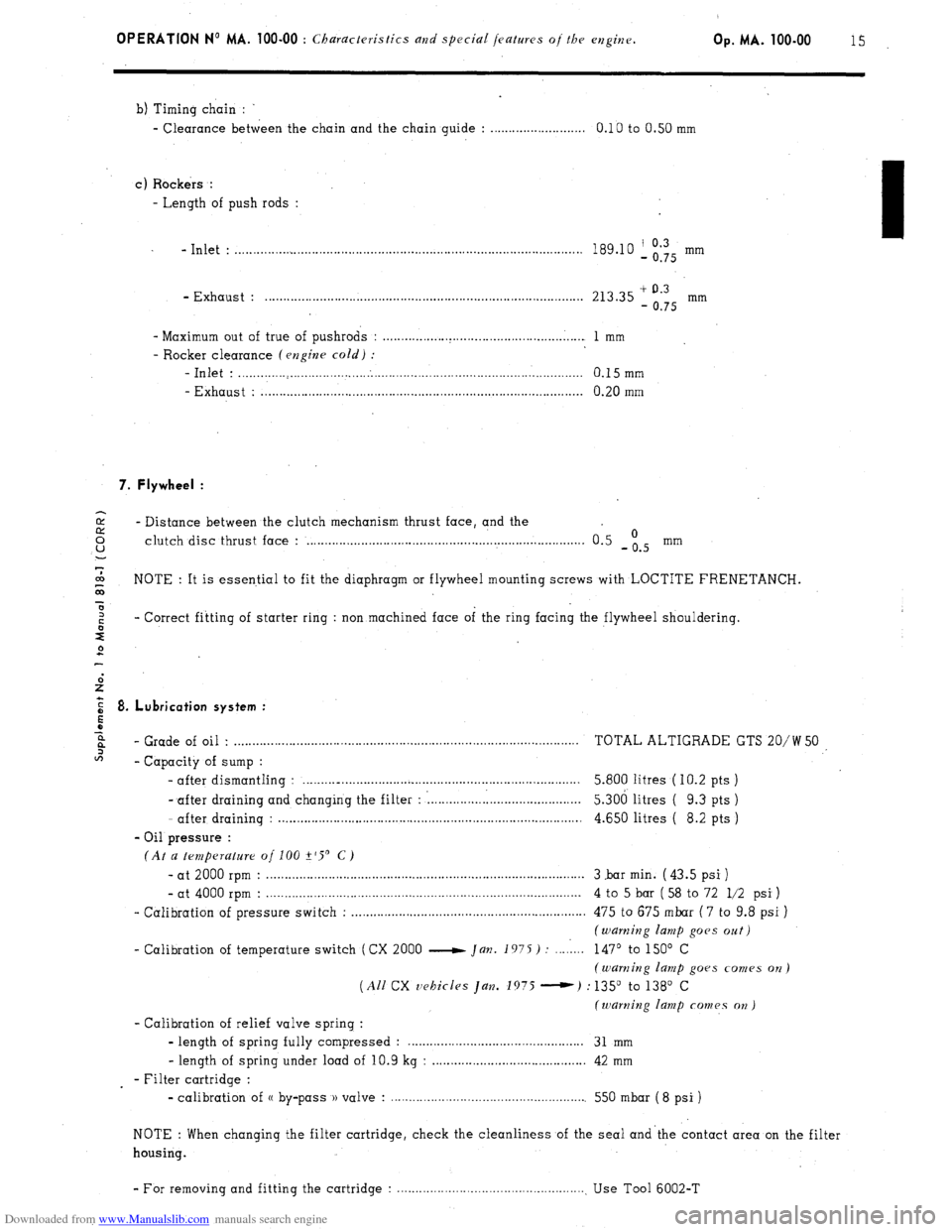
b) Timing chain :
- Clearance between the chain and the chain guide : . . . . . . . . . . . . . . . . . . . . . . . . . . 0.10 to 0.50 mm
c) Rockers :
- Length of push rods :
- Inlet : . . . . . . . . . . . . . . . . . . . . . . . . . . . . . . . . . . . . . . . . . . . . . . . . . . . . . . . . . . . . . . . . . . . . . . . . . . . . . . . . . . . . . . . . . . . . . . 189.10 ‘, Og’Q5 mm
- Exhaust : . . . . . . . . . . . . . . . . . . . . . . . . . . . . . . . . . . . . . . . . . . . . . . . . . . . . . . . . . . . . . . . . . . . . . . . . . . . . . . . . . . . . . . . 213.35 + 0.3
- 0.75 mm
- Maximum out of true of pushrods : . . . . . . . . . . . . . . . . . . . . . . . . . . . . . . . . . . . . . . . . . . . . . . . . . . . . . . . 1 mm
- Rocker clearance (engine cold) :
-Inlet : . . . . . . . . . . . . . . . . . . . . . . . . . . . . . . . . . . . . . . . . . . . . . . . . . . . . . . . . . . . . . . . . . . . . . . . . . . . . . . . . . . . . . . . . . . . . . . 0.15mm
- Exhaust : . . . . . . . . . . . . . . . . . . . . . . . . . . . . . . . . . . . . . . . . . . . . . . . . . . . . . . . . . . . . . . . . . . . . . . . . . . . . . . . . . . . . . . . . 0.20 mm
7. Flywheel :
2 - Distance between the clutch mechanism thrust face, and the 0 u clutch disc thrust face : . . . . . . . . . . . . . . . . . . . . . . . . . . . . . . . . . . . . . . . . . . . . . . . . . . . . . . . . . . . . . . . . . . . . . . . . . . . . 0.5 -is mm
7
co
G NOTE : It is essential to fit the diaphragm or flywheel mounting screws with LOCTITE FRENETANCH.
x
z - Correct fitting of starter ring : non machined face of the ring facing the flywheel shouldering.
s
2
E 8. Lubrication system :
5
z
6%
- Grade of oil . . . . . . . . . . . . . . . . . . . . . . . . . . . . . . . . . . . . . . . . . . . . . . . . . . . . . . . . . . . . . . . . . . . . . . . . . . . . . . . . . . . . . . . . . . . . . . . TOTAL ALTIGRADE GTS 20/W 50
2
- Capacity of sump :
- after dismantling : . . . . . . . .._................................................................. 5.800 litres ( IO.2 pts )
- after draining and changing the filter : : . . . . . . . . . . . . . . . l......................... 5.306 litres ( 9.3 pts )
- after draining : . . . . . . . . . . . . . . . . . . . . . . . . . . . . . . . . . . . . . . . . . . . . . . . . . . . . . . . . . . . . . . . . . . . . . . . . . . . . . . . . . . . 4.650 litres ( 8.2 pts )
- Oil pressure :
(At a temperature of 100 +‘S’ C)
- at 2000 rpm : . . . . . . . . . . . . . . . . . . . . . . . . . . . . . . . . . . . . . . . . . . . . . . . . . . . . . . . . . . . . . . . . . . . . . . . . . . . . . . . . . . . . . . . 3 .bar min. ( 43.5 psi )
- at 4000 rpm : . . . . . . . . . . . . . . . . . . . . . . . . . . . . . . . . . . . . . . . . . . . . . . . . . . . . . . . . . . . . . . . . . . . . . . . . . . . . . . . . . . . . . . 4 to 5 bar ( 58 to 72 l/2 psi )
- Calibration of pressure switch : . . . . . . . . . . . . . . . . . . . . . . . . . . . . . . . . . . . . . . . . . . . . . . . . . . . . . . . . . . . . . . . . 475 to 675 mbar ( 7 to 9.8 psi )
(warning lamp goes oat)
- Calibration of temperature switch (CX 2000 e Jan. 1975) : . . . . 1... 147’ to 150’ C
(warning lamp goes comes on)
(All CX vehicles Jan. 1975 -) : 135” to 138’ C
(warning lamp comes on )
- Calibration of relief valve spring :
- length of spring fully compressed : . . . . . . . . . . . . . . . . . . . . . . . . . . . . . . . . . . . . 31 mm
- length of spring under load of 10.9 kg : . . . . . . . . . . . . . . . . . . . . . . . . . . . . . . . . . . . . . . . . . . 42 mm
- Filter cartridge :
- calibration of (( by-pass )) valve : . . . . . . . . . . . . . . . . . . . . . . . . . . . . . . . . . . . . . . . . . . . . . . . . . . . . . . 550 mbar ( 8 psi )
NOTE : When changing the filter cartridge, check the cleanliness of the seal and’the contact area on the filter
housing.
- For removing and fitting the cartridge : . . . . . . . . . . . . . . . . . . . . . . . . . . . . . . . . . . . . . . . . . . . . . . . . . . . . Use Tool 6002-T
Page 68 of 394
Downloaded from www.Manualslib.com manuals search engine OPERATION No MA. 100-00 : Characteristics and special jeafruvs oj the cvlghv.
Op. MA. 100-00 17
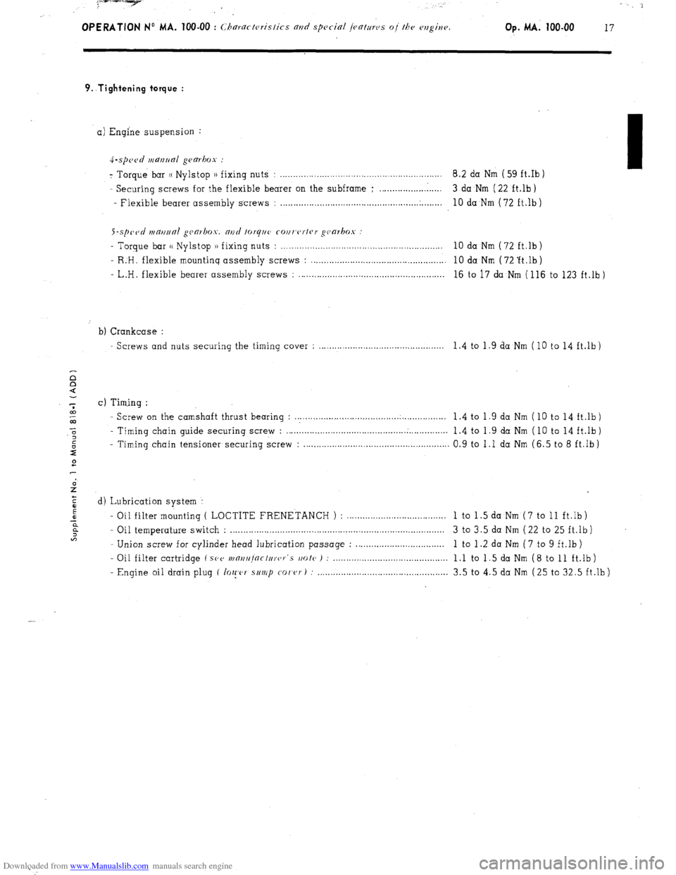
9..Tightening torque :
a) Engine suspension :
4-.spc~~d manrlal gearbox :
7 Torque bar (( Nylstop )) fixing nuts : .............................................................. 8.2 da Nm ( 59 ft.Ib )
- Securing screws for the flexible bearer on the subframe ; ........................ 3 da Nm ( 22 ft.lb)
- Flexible bearer assembly screws :
..................................................... .
........ 10 da Nm (72 ft.lb)
S-sp~~tl n1m11ra1 gca~box. and forq~~c cour,c~rtrr gc~arkos
- Torque bar (( Nylstop )) fixing nuts : . . . . . . . . . . . . . . . . . . . . . . . . . . . . . . . . . . . . . . . . . . . . . . . . . . . . . . . . . . . . . . 10 da Nm (72 ft.lb)
- R:H. flexible mountinq assembly screws : . . . . . . . . . . . . . . . . . . . . . . . . . . . . . . . . . . . . . . . . . . . . . . . . . . . . 10 da Nm ( 72 ‘ft.lb )
- L.H. flexible bearer assembly screws : . . . . . . . . . . . . . . . . . . . . . . . . . . . . . . . . . . . . . . . . . . . . . . . . . . . . . . . . 16 to 17 da Nm ( 116 to 123 ft.lb )
b) Crankcase :
Screws and nuts securing the timing cover : . . . . . . . . . . . . . . . . . . . . . . . . . . . . . . . . . . . . . . . . . . . . . . 1.4 to 1.9 da Nm (10 to 14 ft.lb)
c) Timing :
- Screw on the camshaft thrust bearing : . . . . . . . . . . . .._............................................ 1 .4 to 1 .9 da Nm ( 10 to 14 ft.lb )
- Timing chain guide securing screw : . . . . . . . . . . . ..__................................ . . . . . . . . . . . . . . .
1.4 to 1.9 da Nm ( 10 to 14 ft.lb)
- Timing chain tensioner securing screw : . . . . . . . . . . . . . . . . . . . . . . . . . . . . . . . . . . . . . . . . . . . . . . . . . . . . . . . 0.9 to 1 .I da Nm (6.5 to 8 ft.lb )
d) Lubrication system :
- Oil filter mounting ( LOCTITE FRENETANCH ) : ......................................
1 to 1 .5 da Nm ( 7 to 11 ft.lb )
- Oil temperature switch : .................................................................................. 3 to 3.5 da Nm ( 22 to 25 ft.lb )
- Union screw for cylinder head lubrication passage : ..................................
1 to 1 .2 da Nm ( 7 to 9 ft.lb )
- Oil filter cartridge ( SPV
wnrt/r]nctc/rer‘s rmte ) : ............................................ 1 .l to 1 .5 da Nm ( 8 to 11 ft.lb )
- Engine oil drain plug ( lo~!,c,r s/t~/p
co/‘cr) : .................................................. 3.5 to 4.5 da Nm (25 to 32.5 ft.lb)
Page 71 of 394
Downloaded from www.Manualslib.com manuals search engine OPERATION No MA. 120.0 : Chrrki,,~ the /iminp. Op. MA. 120-O 1
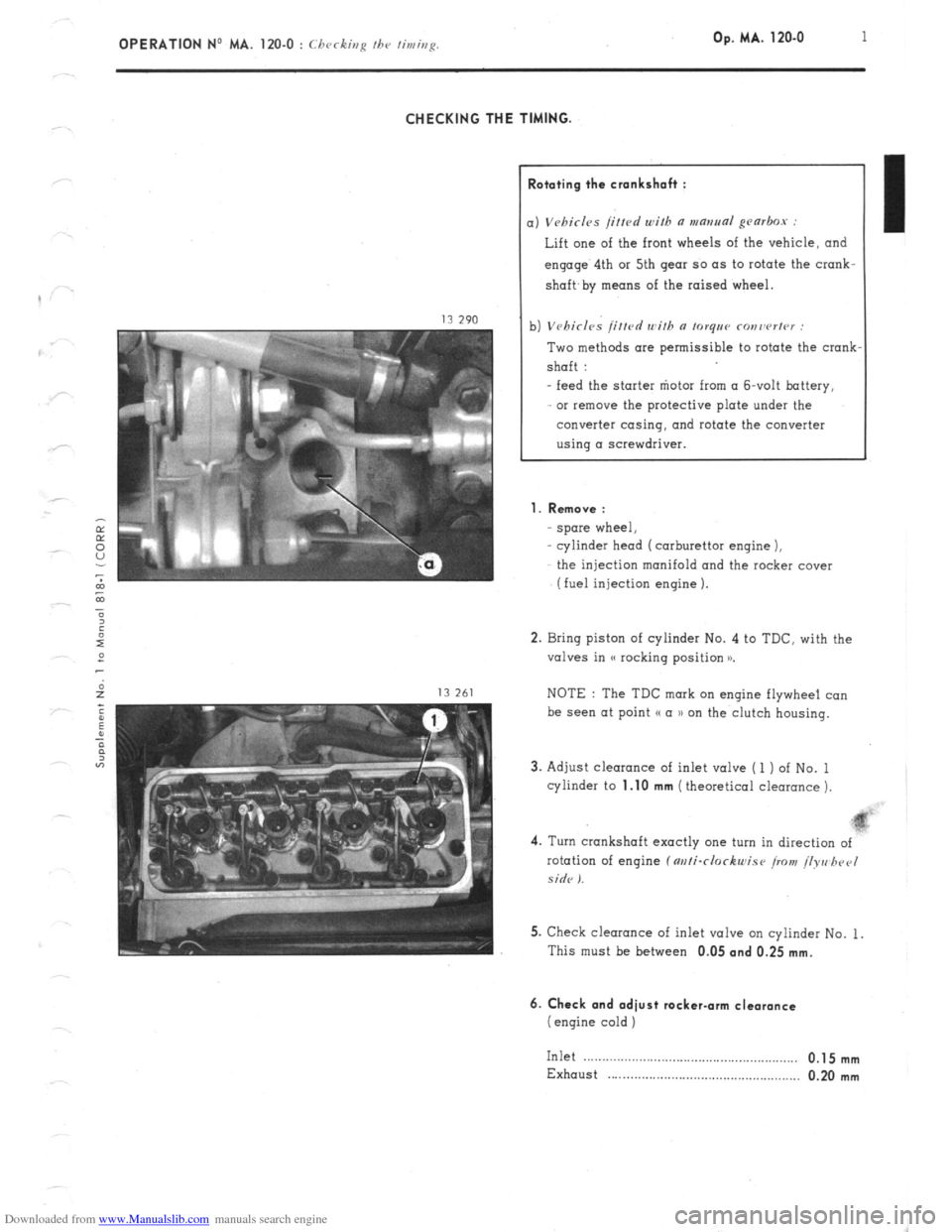
CHECKING THE TIMING.
lototing the crankshah :
) Vebirl~s /i/fed with a mantra~ gearbox :
Lift one of the front wheels of the vehicle, and
engage’ 4th or 5th gear so as to rotate the crank-
shaft,
by means of the raised wheel.
1) Vehicles /itted with n torqee ronrwrter :
Two methods are permissible to rotate the crank
shaft :
- feed the starter “iota from (I &volt battery,
or remove the protective plate under the
converter casing, and rotate the converter
using a screwdriver.
1. Remove :
spore wheel,
cylinder head (carburettor engine 1,
the injection manifold and the rocker cover
(fuel injection engine 1.
2. Bring piston of cylinder No. 4 to TDC. with the
valves in (( rocking position x
NOTE : The TDC mark on engine flywheel co”
be see” at point (( a )) on the clutch housing.
3. Adjust clearance of inlet valve ( 1 ) of No. 1
cylinder to
1.10 mm (theoretical clearance 1.
4. Turn crankshaft exactly one turn in direction of
rotation of engine f m/i-clockwise iro>t! /lyre hpel
side I.
5. Check clearance of inlet valve on cylinder No. 1.
This must be between 0.05
and 0.25 mm.
6. Check and adiust rocker-arm clearance
(engine cold )
Inlet .__....__.............................................,.,, 0.1 5 mm
Exhaust . . . . . . . . . . . . . . . . . . . . . . . . . . . . . . . . . . . . . . . . . . . . . . . . . . . . 0.20 mm
Page 78 of 394
Downloaded from www.Manualslib.com manuals search engine OPERATION No MA. 142-000 : Gcnrrd 1.cnturcs 01. the cnrfxrr~tion. Op. MA. 142-000 7
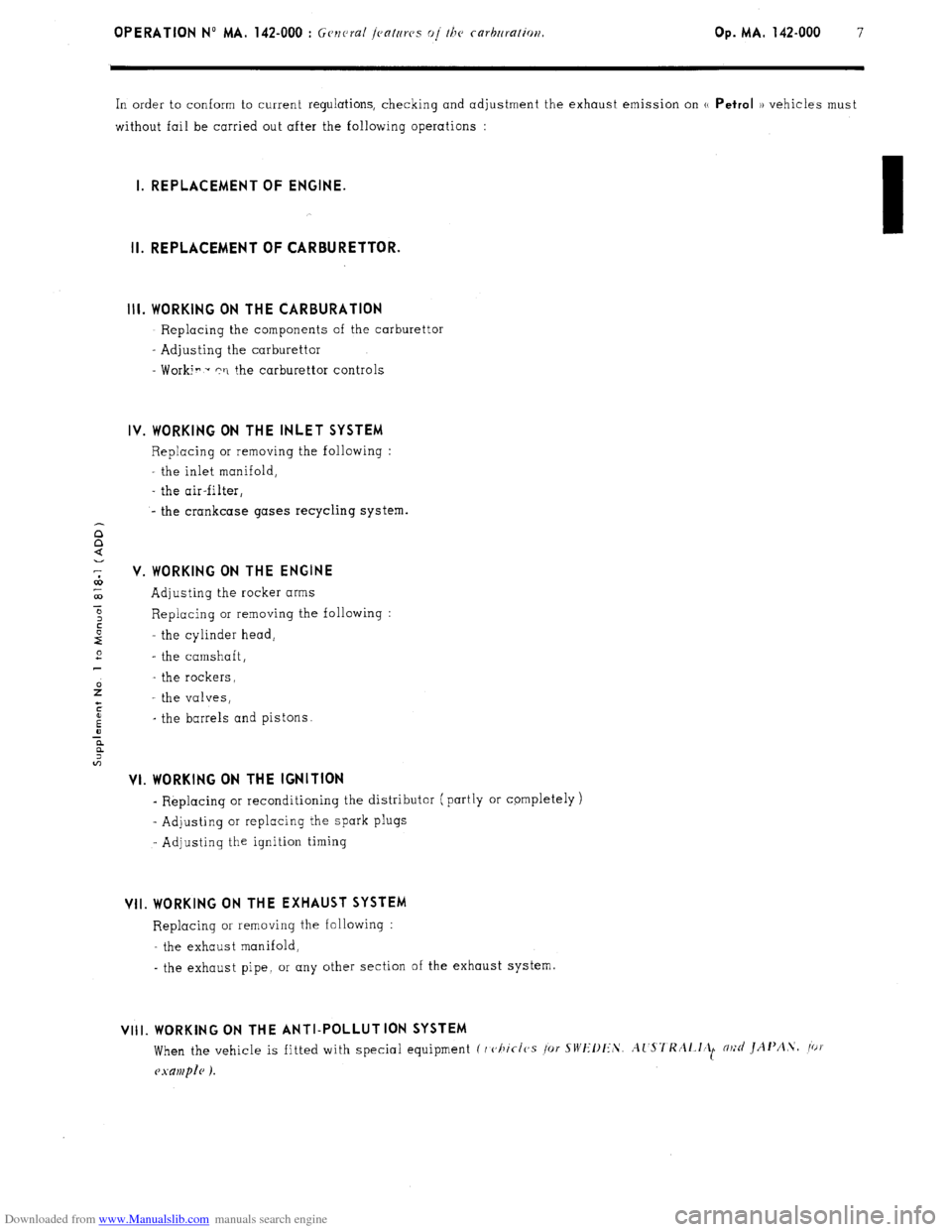
In order to conform to current regulations, checking and adjustment the exhaust emission on u Petrol )) vehicles must
without fail be carried out after the following operations :
I. REPLACEMENT OF ENGINE.
II. REPLACEMENT OF CARBURETTOR.
Ill. WORKING ON THE CARBURATION
- Replacing the components of the carburettor
- Adjusting the carburettor
- Worki? - rri the carburettor controls
IV. WORKING ON THE INLET SYSTEM
Replacing or removing the following :
the inlet manifold,
- the air-filter,
- the crankcase gases recycling system.
V. WORKING ON THE ENGINE
Adjusting the rocker arms
Replacing or removing the following :
the cylinder head,
- the camshaft,
- the rockers,
- the valves,
_ the barrels and pistons.
VI. WORKING ON THE IGNITION
- Replacing or reconditioning the distributor ( partly or cpmpletely )
~ Adjusting or replacing the spark plugs
- Adjusting the ignition timing
VII. WORKING ON THE EXHAUST SYSTEM
Replacing or removing the following :
- the exhaust manifold,
- the exhaust pipe, or any other section of the exhaust system.
VIII. WORKING ON THE ANTI-POLLUTION SYSTEM
When the vehicle is fitted with special equipment C I c,hic-1~s /or SWIIllI:‘S. Al'S7'KAl.l~ll m;d JAI'A.\. /ot
Page 156 of 394
Downloaded from www.Manualslib.com manuals search engine OPERATION NO MA. 210-o : chcJckir,R fl,,d fld;linshp the, iRrlihil Op. MA. 210-O 1
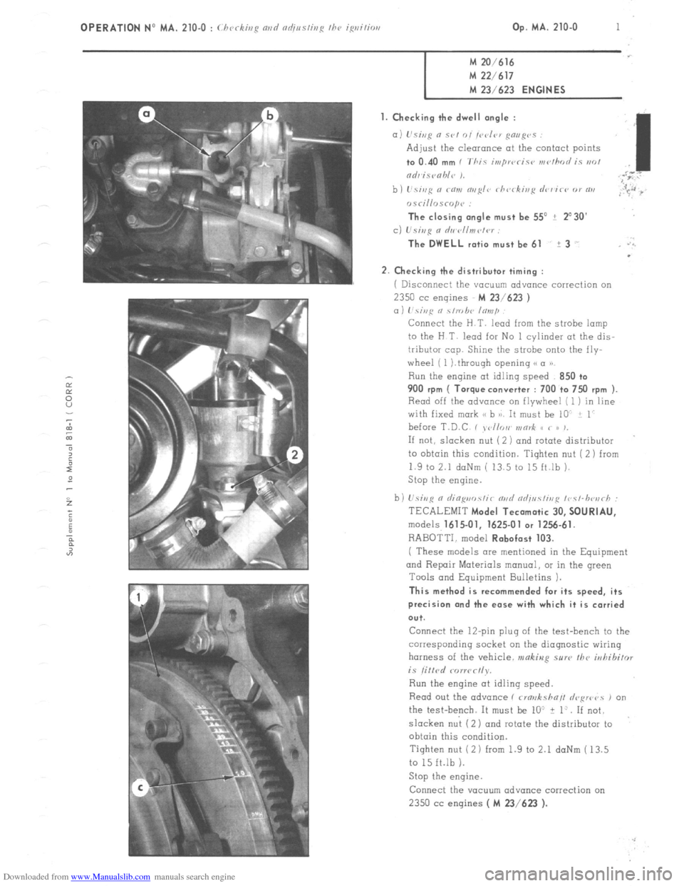
M 20/616 M 22/617
M 23/623
ENGINES
1. Checking the dwell angle :
a) L’siep n SC,, 0, /C‘d‘,V gmg’s
Adjust the clearonce at the contact points to 0.40
mm I ‘Thic in,pwcic~~ wc,/hod iy PK,!
,I
ndr isvohle 1. ;i”
b) I’si,,fi a co,,, o,,~I<~ rh<,rkis~ drr’ir<, or RI,
,r 5.~~ :s
osri//risrop<~ :
The closing angle must be 55’ ? 2’30’
c) L’si,,g 0 d,,~r~ll,,,ct<~r :
The DWELL
ratio must be 61 i 3 .’ .‘.
.
2.
Checking the distributor timing :
i Disconnect the vacuum advance correction on 2350
cc engines M 23/623 )
a) hi,,c o \/robe lo,,,/~
Connect the H.T. lead from the strobe lamp
to the H T lead for No 1 cylinder at the dis-
tributor cop. Shine the strobe onto the fly-
wheel ( 1 ).through opening (( a P)
Run the engine at idling speed 850 +o 900
rpm ( Torque converter : 700 to 7x) rpm ).
Read off the advance on flywheel [ 1 ) in line
with fixed mark (< b 8). It must be 10 i 1
before T.D.C , , <,//or, v,or& S< < /> ,,
If not, slacken nut ( 2 ) and rotate distributor
to ohtoin this condition. Tighten nut (2) from
1.9 to 2.1 daNm ( 13.5 to 15 ft.lb ).
Stop the engine.
b) U.sivR n riin~uo.~~ir m,d od;uc!ir,,~ ~r~c~-lwu~h :
TECALEMIT
Model Tecamatic 30, SOURIAU,
models 1615.01, 1625-01 or 1256.61.
RABOTTI. model Robofast 103.
( These models are mentioned in the Equipment
and Repair Materials manual, OI in the green
Tools and Equipment Bulletins 1.
This method is recommended for its speed, its
precision and the ease with which it is carried
ou+.
Connect the 12-pin plug of the test-bench to the
corresponding socket on the diagnostic wiring
harness of the vehicle. makiug sure the
irrhibifor is litlrd rorwc~ly.
Run the engine at idling speed.
Read out the advance ( rma>rksha// drFwvs , on
the test-bench. It must be lo” + 1:. If not.
slacken nut (2) ond rotate the distributor to
obtain this condition.
Tighten nut (2 1 from 1.9 to 2.1 daNm ( 13.5
to 15 ft.lb 1.
Stop the engine.
Connect the YOCUU~ advance correction on 2350 cc
engines ( M 23/623 ).
Page 157 of 394

Downloaded from www.Manualslib.com manuals search engine 2 OPERATION No MA. 210-O : (.hrrkb,g nnci adiustiug ~hc igrzitim
If CI strobe lamp 01 a diagnosis test bench ore not available. adjusting the distributor timing may be carried out
using LT test lamp. with the engine at static advance point. ( See Chapter III, pages 4 and 5 ).
3. Check the spark regularity :
tisiag n s/robe Imp :
With the distributor timing properly odj.usted ( loi ? 1’ at 850 ?- 50 rpm or 700 ? 50 rpm for torque converter 1,
the advance point must remain within 2”.
1’s;~~ n dinpi,osfir /cs/-hozrh :
The start of opening, or the dwell angle value of the contact breaker ( according to the type of test-bench used )
should not vary by more than 2’ on each boss of the cam.
If this is not the case the rotor clrm 01 the contact breaker bock-plate ore faulty
The distributor must be reconditioned or replaced. II. CHECKING AND ADJUSTING THE DISTRIBUTOR ON A TEST-BENCH
L.21.4 ante LA 2
n Centrifugal adv