ESP Citroen CX 1982 1.G User Guide
[x] Cancel search | Manufacturer: CITROEN, Model Year: 1982, Model line: CX, Model: Citroen CX 1982 1.GPages: 394
Page 241 of 394
Downloaded from www.Manualslib.com manuals search engine V. CHECKING THE ALIGNMENT OF THE FRONT WHEELS
( Front wheel toe-in )
1. Prrpnmtion oi whirlr~. Positior,
whirls. set /he s,rering 10 Ihv straight line positim~( see chapters I and II )
IMPORTANT NOTE
When the steering has been set in I( straight line >) position, (the marks in line with zero
on the sectors of the turntables
1 steering wheel and front wheels must not be touched throughout the whole of
the testing operation.
2. Check readings Ll and L2 ( see chapter I ).
3. Adjust the length of the telescopic rods approximately according to the front track of the vehicle, both rods
being of the some length.
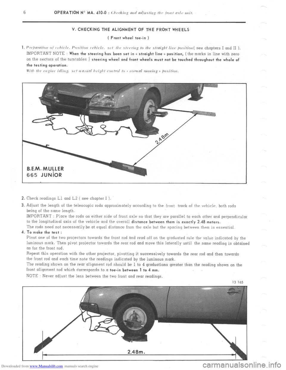
IMPORTANT : Place the rods on either side of front axle so that they are parallel to each other and perpendicular
to the longitudinal axis of the vehicle and the overall
distance between them is exactly 2.48 meters.
The rods need not necessarily be at equal distance from the axle but the spacing between them is essential.
4.
To make the test :
Pivot one of the two projectors towards the front rod hnd read off on the graduated rule thr value indicated by the
luminous mark. Then pivot projector towards the rear rod and move this laterally until the snne reading is obtained
as for the front rod.
Repeat this operation with the other projector, pivotting it successively towards the rear rod and then towards
the front
rod and each time note the readings indicated by the luminous mark.
The reading shown on the rem alignment rod should be 1 to 4 graduations greater than the reading shown on the
front alignment rod which corresponds to a
toe-in between 1 to 4 mm.
NOTE Never adjust the lens between the two front and rear readings.
13 165
Page 350 of 394

Downloaded from www.Manualslib.com manuals search engine OPERATION No MA. 530-00 : (./Jo).N~.I(,I.;sI~~-s I>/ I/I<> vfvctrir-nl c~NI/~~~I/~~~IIs.
Op. MA. 530-00 3
III. STARTER MOTORS.
ALL ENGINES
DUCELLIER 6236 AND PARIS-RHONE D 9 E 16 STARTERS
CHARACTERISTIC CURVES
daNm
0.5 - 5
0 =f N
?l!fBl 7
a3
2
Trrt rt-ul I I I I / I 1 0
? I s1
2 -I
2 ’ I I III I I I I
F
200 400 600 800 1 AMPS
2
1000 2000 3000 4000 N RPM ;
E
r:
z, CHECKING.
ON VEHICLE : Ensure that battery is fully charged, and measure the following :
a) Current consumed,( pinion locked ) ._... . . . . . . . . .: . . . . . . . . . . . . . . . . . . . . . . . . . . 440 A ( 6236 ) and 450 A ( D 9 E 1 6 )
b) Current consumed when starting ( at 20’ C ) . . . . . . . . . ,.......,........................... 150 to 170 A
c) Current consumed with no load ( starter removed ) ,.,.,.,. ..,.,. ,...,.,...,.....,.,.,.,.,.,. 50 A maximum
BENCH TEST
: Use a 12 V - 200/40 Ah fully charged battery.
MEASUREMENTS
. Average torque at 1000 rpm _ .................................................................
Corresponding current ._ ............................................................... ......
. Torque locked ............................ ........................ ........................ ............
Corresponding current ._ ........................... ...... ............ ......................
Voltage ..................................................... ...... ........................................
Maximum power ._ ........................................................... ..........................
Voltage ....................................................................................................
Current .............................................................................................
Torque ._ ................................................................................................... DUCELLIER PARIS-RHONE
6236 D9E16
1.85 daNm (6 1 ft.lb)
300 A
.15 daNm (1.08 ft.lb)
440 A.
7.4 v
965 W
9.4 v
240 A
1.6 daNm ( 4.3 ft.lb) 1.83 daNm (6 ft.lb)
270 A
1.155daNm (1.12 ft.lb)
,450 A
7v
920 w
9v
215 A
0.6 daNm (4.3 ft.lb)
Page 354 of 394
Downloaded from www.Manualslib.com manuals search engine Il. CHECKING THE REGULATED TENSION OF THE REGULATORS
CHARACTERISTICS
- Two-stage voltage regulator : Ref : DUCELLIER 8379 A, PARIS-RHONE AYC 2114 and AYC 2117.
SEV-MARCHAL F. 14 V 72717102
These voltage regulators determine the intensity of the current in the alternator inductor in order to maintain a
constant regulated voltage at the battery terminals.
, CHECKING THE REGULATED VOLTAGE
(.‘hcckitlg ti7c rc~~~~~l~tc~cl u~IIcl,~c~ mris t 170 rnrric,rl out u,ith a lrilly darg~~rl hnttcry.
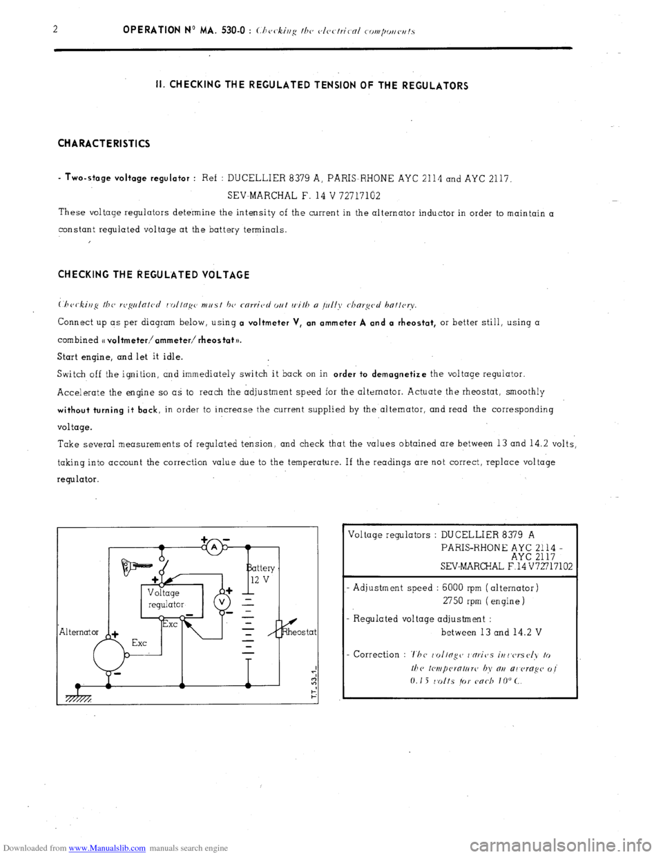
Connect up as per diagram below, using a voltmeter V, an ammeter A and a rheostat, or better still, using a
combined
o voltmeter/ammeter/ rheostat )).
Start engine, and let it idle.
Switch off the ignition, and immediately switch it back on in
order to demagnetize the voltage regulator.
Accelerate the engine so as to reach the adjustment speed for the alternator. Actuate the rheostat, smoothly
without turning it back, in order to increase the current supplied by the alternator, and read the corresponding
voltage.
Take several measurements of regulated tension, and check that the values obtained are between 13 and 14.2 volts,
taking into account the correction value due to the temperature. If the readings are not correct, replace voltage
regulator.
Exe Voltage regulators : DUCELLIER 8379 A
PARIS-RHONE ;;E ;;;; -
SEV-MARCHAL F.14 V72717102
- Adjustment speed : 6000 rpm (alternator)
2750 rpm (engine)
- R egulated voltage adjustment :
between 13 and 14.2 V
Page 359 of 394
Downloaded from www.Manualslib.com manuals search engine OPERATION No MA. 560.0 : ~hrrkin~ o,,d oc/@s/i,,g I/><, wiurisrrrr,, wip’r. Op. MA. 560.0
1
Fi
m
0 CHECKING AND ADJUSTING THE WINDSCREEN WIPER.
FRONT WINDSCREEN WIPER MOTOR
CHARACTERISTICS.
Manufacturer DUCELLIER
Reference No. 4966 A
Field coils Ferrite
Armature : Endfloot (adjustable by means of stop-screw) : 0.2 mm
Nominal dia. of commutator :
24 mm
Min. dia. after machining : 23 mm
Brushes : Ref. No. :
CL 7239
Minimum length after wear : 5.5 mm
Ratio : .._...................................................................................................
44 1
Connection and circuit diagram as in Op. MA. 510 00.
ELECTRICAL CHECK. BOSCH
0390 346 127
Ferrite
0
23.2 mm
23 mm
1.394.320-058 059, 062
7.5 mm
49 1
1. First speed :
Nominal power : IO watts
Speed, under no load, at 13.5 volts = 50 rpm Corresponding current = I.8 A
Torque, motor locked, at 13.5 volts = 1.9 da Nm 7 13.74 ft.lb min. Corresponding current 18 A max.
Torque at 40 rpm and 13.5 volts = 0.2 do Nm (1.45 ft.lb) Correspondinq current = 5.5 A max.
- Torque ot 20 rpm and 13.5 volts = 1.07 da Nm (7.74 ft.lb) min Corresponding current = 13.2 A max.
2. Second speed :
Nominal power : 15 watts
Speed under no load at 13.5 volts = 70 rpm Corresponding current = 2.3 A
Torque motor locked at 13.5 volts = 1.5 do Nm (IO.85 ft.lb) min Corresponding current = 21 A max
Torque at 60 rpm and 13.5 volts = 0.2 da Nm (1.45 ft.lb) min Corresponding current = 7 A max
Torque ot 30 rpm and 13.5 volts = 0.9 da Nm (6.51 ft.lb) min Corresponding current = 14.7 A mrx.
ADJUSTMENT OF WINDSCREEN WIPER ARM
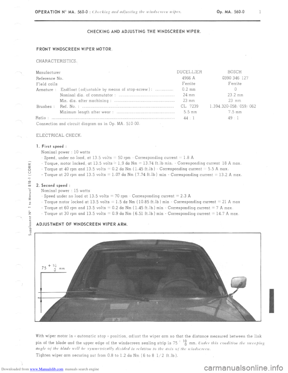
With wiper motor in (< automatic stop )/ position, adjust the wiper arm so that the distance measured between the link
pin of the blade and the upper edge of the windscreen sealing strip is 75 ‘t
mm. L’vd‘ar /his rondiliw, /he 51, rvp;,,g
m,g/r 0, /he bladr ,,~i// hv symv,r~/rirn//v dil idrd it, w/n/io,, 10 /he O.YiS “, I/w r,‘iri
Tighten wiper arm securing out from 0.8 to 1.2 da Nm (6 to 8 l/2 ft.lb).
Page 373 of 394
Downloaded from www.Manualslib.com manuals search engine 4 OPERATION No MA. 640.0 : ( ht.< k;nS our/ ndj,,~/ir,~ I/><, ni~.rr,r,r/i/ior,i,,F sm,<,,,,.
,s ~16 2. Check the ccmpress~r oil level :
76.54
NOTE This check con only be carried out after having
drained the circuit. If not, dangerous splashing of oil
and refrigerating fluid occur. 0vrs rowed vd. I/,<’
rornprc ‘i YC,l hr ,I,. Yi,,S I,,,, s, /w
gauge MR. 630-73/ 15 until it reaches the hottam
of the casing ( rotate crankshaft if necessary 1. The
oil level must be between the min. and max. marks on
the qauqe ( which correspond to a depth of oil of 21
to 29 mm ).
b I If necessary top up using TOTAL (< LUNARIA 25 ),
or SUNISO No.5 01 TEXACO CAPELLA << E )a
grade 500.
c) Remove gouge MR ‘630-73/ 15 and position the plug
with its seal.
3. Create a V(IEYU~ in the circuit :
NOTE This consists in creotinq a vacuum as complete
as possible in the circuit. to eliminate (by evaporation j
any trace of water which
would hinder the operation of
the refrigerating system.
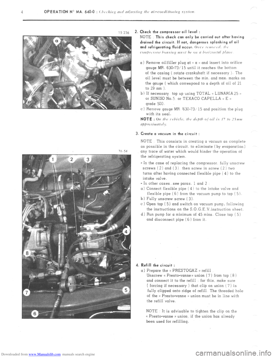
- In the case of replacing the compressor. fully unscrew
screws ( 2 1 and ( 3 1 then screw in screw ( 2 ) two
turns after having connected flexible pipe ( 4) to the
intake valve.
* In other cases see paras. 1 and 2
a) Connect flexible pipe ( 4 i to the intake valve and
flexible pipe ( 6 1 from the vacuum pump to top ( 5 1.
b) Fully unscrew screw ( 3 1.
c ) Open tap [ 5) and switch on vacuum pump. following
the instructions on the S.O.G.E.V.instruction sheet.
di Run pump for a minimum
of 45 mins. Close tap ( 5)
and disconnect pipe ( 6 1 from it.
4. Refill the circuit :
a) Prepare the <( PRESTOGAZ n refill
Unscrew cf Presto-vanneu union ( 7 ) from tap ( 8 1
and connect it to the refill for this. make sure
I forcing if necessary ) that clip on union ( 7) is
fully clipped onto ridge of refill The threaded hole
of the o Presto-vanne )a union must be in line with
the refill valve.
NOTE It is advisable to tighten the clip on the
o Presto-wane >) union. if the union has already
been used for refilling.
Page 384 of 394
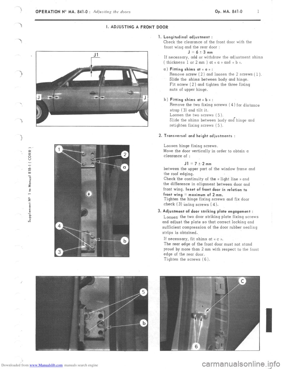
Downloaded from www.Manualslib.com manuals search engine OPERATION No MA. 841-O : Adjusting fh~ doors Op. MA. 841-O 1 I. ADJUSTING A FRONT DOOR
1. Longitudinal adiustment :
Check
the clearance of the front door with the
front wing and the rear door : J=6+_3mm
If necessary. add or withdraw the adjustment shims
( thickness 1 or 2 mm ) at <( a 1) and << b to_ a) Fitting shims at SC a u :
Remove screw (2) and loosen the 2 screws ( 1).
Slide the shims between hody and hinge.
Fit screw (2) and tighten the three fixing
nuts of upper hinge.
b) Fitting shims at <, b n :
Remove the two fixing screws (4) for distance
strop (3) and tilt it.
Loosen the two screws (5 ).
Slide the shims between body &hinge and
retighten fixing screws (5 ). 2. Transversal and height adjustments :
Loosen hinge fixing screws.
Move the door vertically in order to obtain a
clearance of : Jl = 7 +‘2mm
between the upper port of the window frame and
the roof edging.
Check ‘the continuity of the a light line 1) and
the difference in alignment between door and
front wing. Inset of front door in relation to
front wing = maximum of 2 mm.
Tighten the hinge fixing SCWNS and fix door
check (3) using screws (“4). 3. Adjustment of door striking plate engagement :
Loosen. the two door striking plate fixing screws
and adjust the plate so that correct locking and
sufficient compression of the door rubber sealing
strips is obtained.
If necessary, fit shims at (cc )P.
The rear edge of the front door must not stand
proud by more than 2 mm with respect to the front
edge of the rear door.
Tighten the screws (6 ).