ESP Citroen CX 1982 1.G Workshop Manual
[x] Cancel search | Manufacturer: CITROEN, Model Year: 1982, Model line: CX, Model: Citroen CX 1982 1.GPages: 394
Page 3 of 394
Downloaded from www.Manualslib.com manuals search engine OPERATIONS
The sequence of operations has been devised in order to obtain the best standard of work in the
shortest possible time.
The numbering of the operations is made up as follows
a) The code letter for the car (/ MA 3) for all CX vehicles except
b ) A number made up of three figures denoting the unit or its component.
c ) A figure code designating the type of repair
- the figures 0 0 0 indicate the characteristics of the car
the figures 0 0 indicate the characteristics of the unit
- the figure 0 indicates checks and adjustments
the figures 1 4. 7 indicate removal or fitting
- the figures 2. 5. 8 indicate dismantling or reassembly and
the figures 3 6 9 indicate reconditioning
The thumb-indexing which corresponds to the list of operations enables the particular operation
to be found without difficulty. TOOLING
Special tooling is denoted in the text by a number followed by the letter ‘I
The part-numbers inferior to the 6000 series concern tools aiready in use and common to vehicles
previously introduced and to CX vehicles.
The 6000 series refers to tools specially designed for CX vehicles
Additional tools of local manufacture are indicated in the text by a number preceded by the index
MR manufacturing drawings for these tools appear at the end of the particular volume filed in
numerical order. TIGHTENING TORQUES :
Torques are expressed in the following units
either in metres Newton ( m.N ) the legal unit for measuring torque. with the corresponding
amount in metre-kilogrammes ( m.kg )
or in decanewtonmetres ( da Nm ) 9.8i Nm 1 m.kg ci.981 daNm
The numbers corresponding to the torques are (t rounded off 1)
Examples 2 m.N 0.2
m..kg 60 m.N 6
m.kg
IMPORTANT When a tightening torque figure is followed by the words 11 torque wrench 11 the
operution must without fail be carried out with a torque wrench.
IMPORTANT WlTHOUT FAIL after each operation or group of operations there is a chapter
headed (, TIGHTENING TORQUES ,,; the screws nuts or studs which are underlined
indicate
that they are of a special grade ,c SECURITY HARDWARE 1). When refitting it is ESSENTIAL
to use this type of HARDWARE TO THE EXCLUSION OF ANY OTHER. ADVISORY SERVICE
For a!1 technical information concerning these vehicles please contact
The Service Department,
Citroen Cars Ltd..,
Mill St.,
Slough Berks. GE. Tel. Slough 23808
or DEPARTEMENT TECHNIQUE APRES-VENTE
ASSISTANCE TECHNIQUE -
92000 NANTERRE - FRANCE - Tel. 204 40 00 :
.- ---
Page 41 of 394
Downloaded from www.Manualslib.com manuals search engine OPERATION No MA. 01 : 1’. I, -1’ IO c ( lOi, o/ I/J<, c~lcrlricnl /l/lilS. Op. MA. 01 1 PROTECTION OF THE ELECTRICAL UNITS
PRECAUTIONS WHEN CARRYING OUT WORK ON THE CAR
1. Battery :
a) Disconnect the negative terminal first, then the positive one.
b) Ensure the battery is properly connected, with the negative terminal being connected
to earth.
c) Carefully connect both leads to the battery terminals, the negative lead being connected
last.
Before connecting the negative lead ensure that there is no flow of current. This can
be established by briefly touching the negative terminal pith the lead end : sparks
indicate a short circuit which must be corrected first.
d) Before using the starter ensure that the two leads are correctly tightened on their
respective terminals. $ 2. Alt ernator-Regulator :
a) Do not rotate the alternator unless it is connected to the battery.
0
2
2 b) Before connecting the alternator ensure that the battery is correctly connected
2 (negative terminal to earth ).
c) Do not check the operation of the alternator by short-circuiting either the positive or
the u EXC )) terminals and the earth terminal.
d) Take care not to reverse the leads connected to the regulator.
e) Do not attempt to re-energize the alternator : this is never necessary and in any case
would damage both the alternator and the regulator.
f ) Do not connect a suppressor capacitor at the u EXC )) terminal of the alternator or the
regulator.
g) Do not connect a charging unit to the battery and never carry out arc welding ( or spot
welding) on the car chassis unless both the positive and the negative leads are
disconnected from the battery. 3. Ignition coil :
4. Q.I. Headlamps :
a) Connect the supply lead of the coil to the external ballast resistor terminal and not to
the coil itself.
b) Connect the suppressor with a jump lead to the feed terminal of the coil. Only fit the
suppressor recommended by the factory.
a) Only replace a Q.I. bulb with the headlamps switched off. After having used the head-
lamps, it is wise to let them cool down for five minutes before handling.
b) Do not touch a Q.I. bulb with bare fingers. Any fingerprints on the bulb must be cleaned
off with soapy water and the bulb dried with a lint-free cloth.
Page 90 of 394
Downloaded from www.Manualslib.com manuals search engine OPERATION No MA. 142-O : Adj,,s/iaji f/a<, rarhnrt,//or Op. MA. 142.0
1
ADJUSTING THE IDLING SPEED
To carry out this adjustment, the following is needed
A tachometer
A device lor checkinq idling speed adjustments on the carburettor ( or on approved gas analyser )
- A CDA 23 checking oppmotus or a workshop test bench ( equipment mentioned in the Equipment and Repair
Materials list, or in the Tools and Equipment notes green notes )
NOTE : WEBER Carburettors ref. No W 54-50, 55-50, 69-50, 74-50 fitted on 1977 models onwards ore fitted with a
fool-proof plug ( white ) on the mixture screw. To adjust the exhaust emission, this plug has to be
removed, and
replaced, after adjustment, with a a Repair PI plug ( black ). See Op. MA, 142-000 for removing and fitting the plug,
and the necessary tools.
ADJUSTMENT CONDITIONS
1.
The idling speed adjus!ment must be carried out on an engine on which the rocker clearances and the ignition
are correctly set. with a clean air filter and
with the engine in good order.
2. Check that the butterflies return fully to their stops.
3. 30 not let pnythinq except the ignition and the engine cooling fan ( or ions ) impose any load on the alternator.
4. Run the engine to bring the
oil temperature up to 70 to 80’ C ( wait for the electric cooling fan ( or fans 1 to cut
in 1.
I. M 20/616, M 22/617, M 23/623 ENGINES I i< ?I< (5 wi/hr ,111 /or<,,,< co,1, <,r,cr or air ro,,di/io,ii?,g I ,I ‘-/
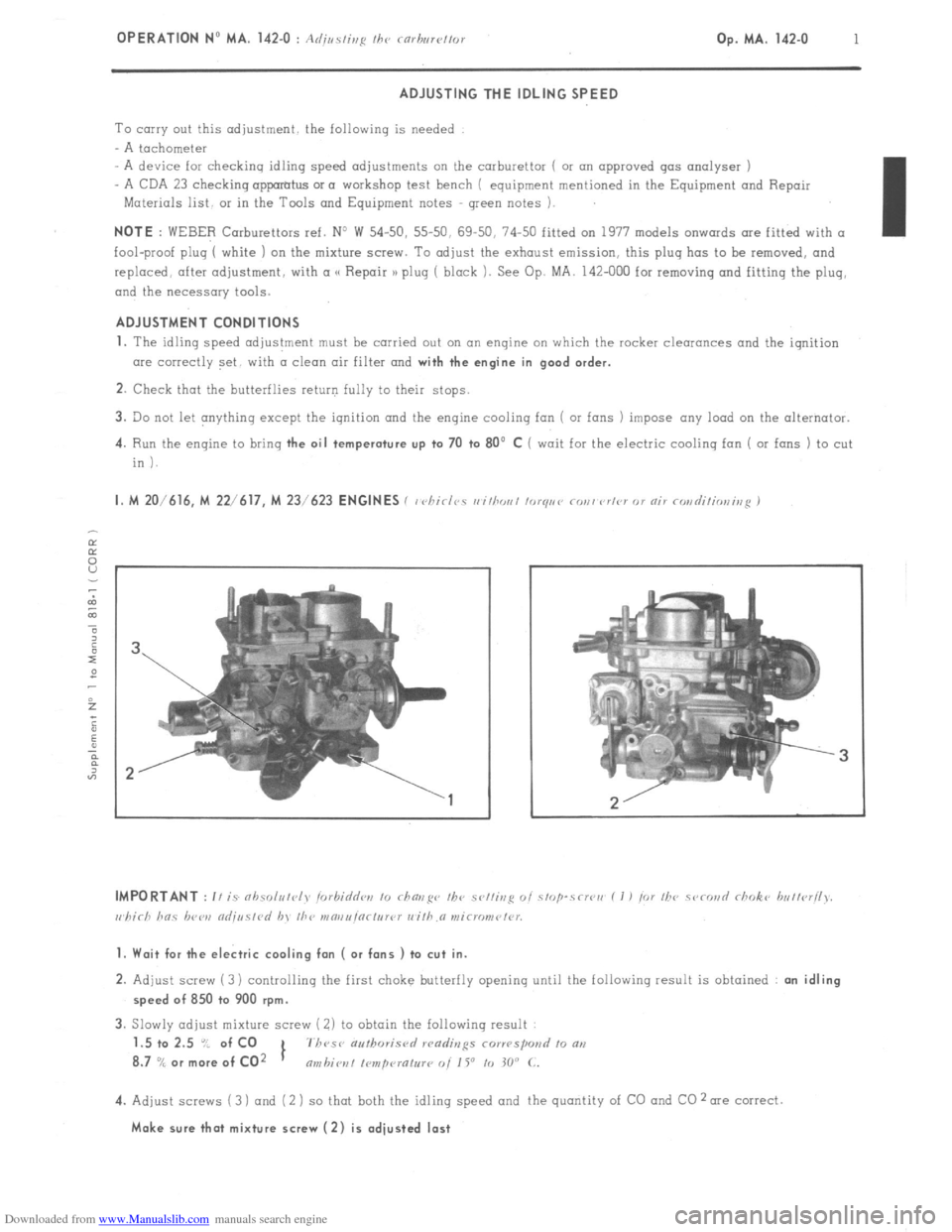
1. Wait for the electric cooling fan ( or fans ) to cut in.
2. Adjust screw (3) controlling the first choke butterfly opening until the following result is obtained : an idling
speed of 850 to 900 rpm.
3. Slowly adjust mixture screw ( 2) to obtain the following result
1.5 to 2.5 “/ of CO
1 7h~se authoris<,
8.7
% or more of CO2 nmbiot~l I~mpcuatur~ 0i 1 Y to 30” C.
4. Adjust screws (3 ) and (2 ) so that both the idling speed and the quantity of CO and CO 2 me correct.
Make sure that mixture screw (2) is adjusted last
Page 156 of 394
Downloaded from www.Manualslib.com manuals search engine OPERATION NO MA. 210-o : chcJckir,R fl,,d fld;linshp the, iRrlihil Op. MA. 210-O 1
M 20/616 M 22/617
M 23/623
ENGINES
1. Checking the dwell angle :
a) L’siep n SC,, 0, /C‘d‘,V gmg’s
Adjust the clearonce at the contact points to 0.40
mm I ‘Thic in,pwcic~~ wc,/hod iy PK,!
,I
ndr isvohle 1. ;i”
b) I’si,,fi a co,,, o,,~I<~ rh<,rkis~ drr’ir<, or RI,
,r 5.~~ :s
osri//risrop<~ :
The closing angle must be 55’ ? 2’30’
c) L’si,,g 0 d,,~r~ll,,,ct<~r :
The DWELL
ratio must be 61 i 3 .’ .‘.
.
2.
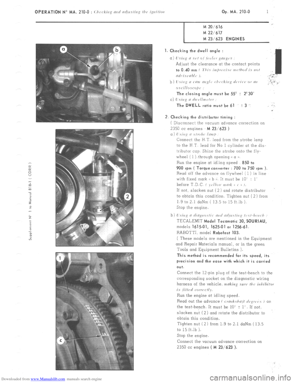
Checking the distributor timing :
i Disconnect the vacuum advance correction on 2350
cc engines M 23/623 )
a) hi,,c o \/robe lo,,,/~
Connect the H.T. lead from the strobe lamp
to the H T lead for No 1 cylinder at the dis-
tributor cop. Shine the strobe onto the fly-
wheel ( 1 ).through opening (( a P)
Run the engine at idling speed 850 +o 900
rpm ( Torque converter : 700 to 7x) rpm ).
Read off the advance on flywheel [ 1 ) in line
with fixed mark (< b 8). It must be 10 i 1
before T.D.C , , <,//or, v,or& S< < /> ,,
If not, slacken nut ( 2 ) and rotate distributor
to ohtoin this condition. Tighten nut (2) from
1.9 to 2.1 daNm ( 13.5 to 15 ft.lb ).
Stop the engine.
b) U.sivR n riin~uo.~~ir m,d od;uc!ir,,~ ~r~c~-lwu~h :
TECALEMIT
Model Tecamatic 30, SOURIAU,
models 1615.01, 1625-01 or 1256.61.
RABOTTI. model Robofast 103.
( These models are mentioned in the Equipment
and Repair Materials manual, OI in the green
Tools and Equipment Bulletins 1.
This method is recommended for its speed, its
precision and the ease with which it is carried
ou+.
Connect the 12-pin plug of the test-bench to the
corresponding socket on the diagnostic wiring
harness of the vehicle. makiug sure the
irrhibifor is litlrd rorwc~ly.
Run the engine at idling speed.
Read out the advance ( rma>rksha// drFwvs , on
the test-bench. It must be lo” + 1:. If not.
slacken nut (2) ond rotate the distributor to
obtain this condition.
Tighten nut (2 1 from 1.9 to 2.1 daNm ( 13.5
to 15 ft.lb 1.
Stop the engine.
Connect the YOCUU~ advance correction on 2350 cc
engines ( M 23/623 ).
Page 161 of 394
Downloaded from www.Manualslib.com manuals search engine OPERATION No MA. 210-O a : C/ ‘CC ,r,,q rind ndj,,s/isp I/W ~~/<~c-/mr,ir ip,itior, 5?‘.5/‘.,11 k’ Op. MA. 210-O a 1
M 23/622 ENGINE
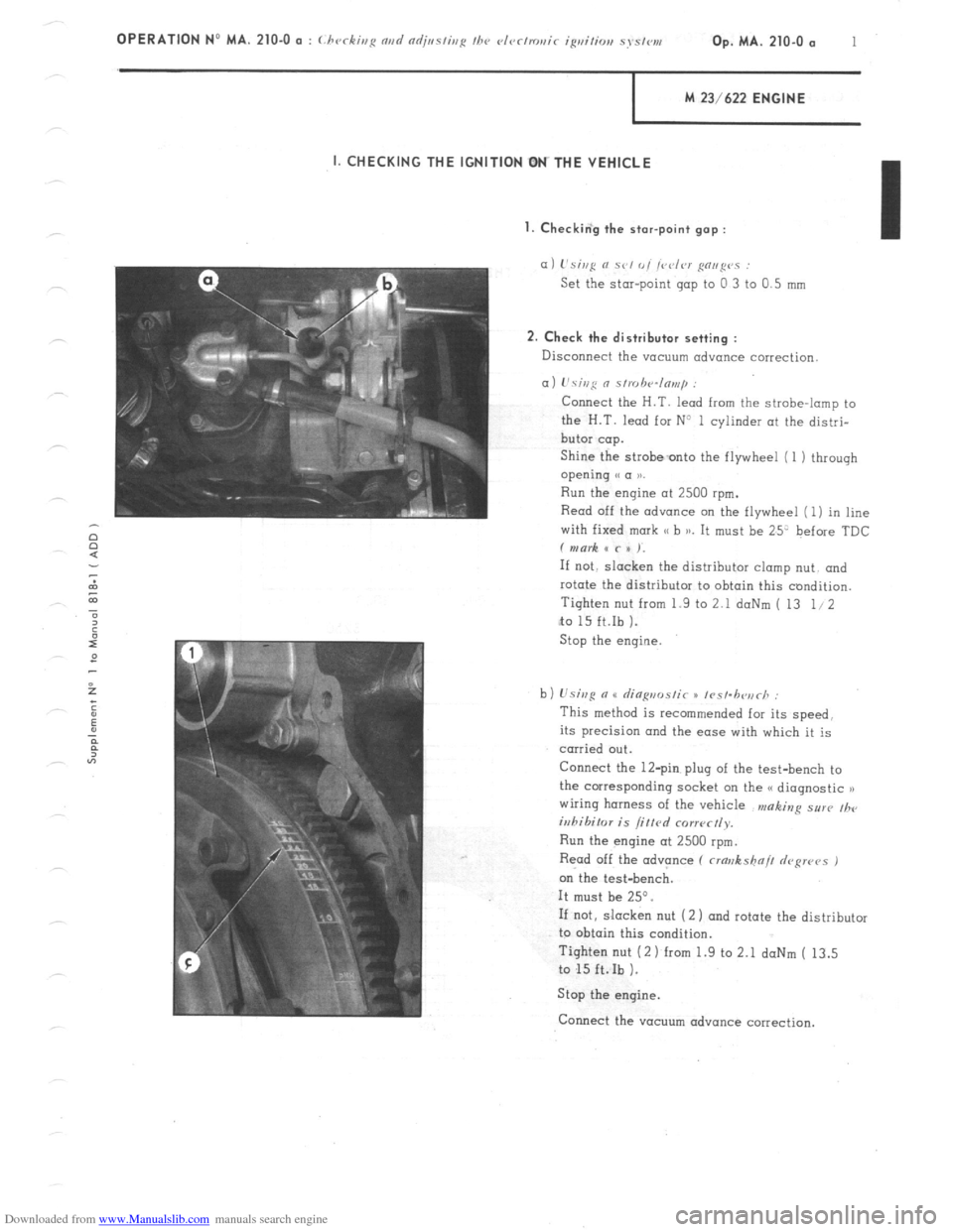
I. CHECKING THE IGNITION OM THE VEHICLE
I. Checkin‘g the star-point gap :
a) L’si,,g N se, 0, /vdrr g”,,g”” :
Set the star-point gap to 0 3 to 0.5 mm
2. Check the distributor setting :
Disconnect the vacuum advance correction
a) L’sing 0 s/,uh‘4n,,,,p :
Connect the H.T. lead from the strobe-lamp to
the H.T. lead for N3 1 cylinder at the distri-
butor cap.
Shine the strobeonto the flywheel (1 1 through
opening e a 1).
Run the engine at 2500 rpm.
Read off the advance on the flywheel (1) in line
with fixed mark SC b )a. It must be 25’ before TDC
f mark x c x ).
If not. slacken the distributor clomp nut. and
rotate the distributor to obtain this condition.
Tighten nut from 1.9 to 2.1 doNm ( 13 1.12
to 15 ft.Ib ).
Stop the engine
b) Usisg n u rlia~,,ms/ir x /rs/.h<~,irh :
This method is recommended for its speed.
its precision and the ease with which it is
carried out.
Connect the 12-pin plug of the test-bench to
the corresponding socket on the G< diagnostic n
wiring harness of the vehicle n,aking sur(, ,h,
iuhihilor is /if/cd corr~~ctly.
Run the engine at 2500 rpm.
Read off the advance (
crawkshn// depws 1
on the test-bench.
It must be 25”.
If not, slacken nut (2 1 and rotate the distributor
to obtain this condition.
Tighten nut (2 1 from 1.9 to 2.1 daNm ( 13.5
to 15 ft.Ib ).
Stop the engine.
Connect the vacuum advance correction.
Page 168 of 394
Downloaded from www.Manualslib.com manuals search engine Op. MA. 221-O 3 -
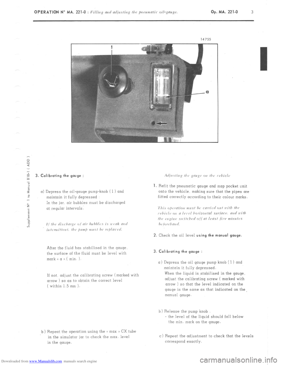
5 3. Calibrating the gouge :
”
6
I
a) Depress the oil-gouge pump-knob i 1) and
:
maintain it fully depressed
f In the jar. air bubbles must be discharged
; at regular intervals.
:
u
P
F
“3 , , ,hr ,I;.7 rhorg<~ ,, I nir hn hhlcs is I, vnk rind
;,,,<,r,,,i,,l~r,,. the primp m,, 51 hl, rcplnrl~d.
After the fluid has stabilised in the gauge
the surface of the fluid must be level with
mark o a a) ( min. i-
If not. adjust
the calibrating screw (marked with
(IIIOW ) so as to obtain the correct level
( within 1.5 mm 1.
b ) Repeot the operation using the << max a) CX tube
in the simulotar jar to check the max. level
in the gauge. 3. Calibrating the gauge :
a) Depress
the oil qauqe pump knob ( 1 1 and
maintain it fully depressed.
When the liquid is stabi!ised in the gouge,
adjust the calibrating screw 1 marked with
arrow ) so that the level indicated on the gauge
is the same as that indicated on the
manual gauge.
b) Release the pump knob
- the level of the liquid should fall below
the min. mark on the gauge.
c) Repeat the adjustment to check that the levels
correspond exactly.
Page 189 of 394
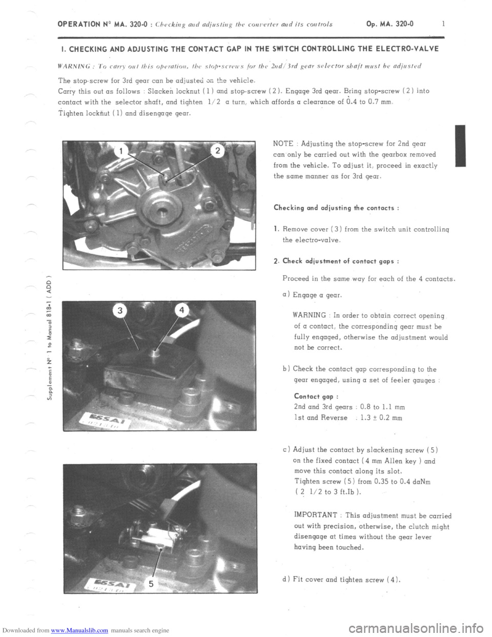
Downloaded from www.Manualslib.com manuals search engine OPERATION No MA. 320-O : Checking md czdjssting fhe ronw’rtcv artd its corrtrols Op. MA. 320.0 1 I. CHECKING AND ADJUSTING THE CONTACT GAP IN THE SWITCH CONTROLLING THE ELECTRO-VALVE
The stopscrew for 3rd gear can be adjusted SK the vehicle.
Carry this out as follows : Slacken locknut ( 1 ) and stopscrew (2 ). Engage 3rd gear. Bring stop-screw i 2 1 into
contact with the selector shaft. and tighten l/2 a turn, which affords a clearance of a.4 to Cl.7 mm.
Tighten lockfiut ( 1) and disengage gear.
NOTE : Adjusting the stop-screw for 2nd gear
con only be carried out with the gearbox removed
from the vehicle. To adjust it, proceed in exactly I
the same manner as for 3rd gear. Checking and adjusting the contacts :
1.
Remove cover ( 3) from the switch unit controliinq
the electro-valve. 2. Check adjustment of contact gaps :
Proceed in the same way far each of the 4 contacts.
a) Engage a gear.
WARNING In order to obtain correct opening
of a contact, the corresponding gear must be
fully engaged. otherwise the adjustment would
not be correct.
b) Check the contact gap corresponding to the
gear engaged, using a set of feeler gauges : Contact gap :
2nd
and 3rd gears 0.8 to 1.1 mm
1st and Reverse 1.3 ? 0.2 mm
c 1 Adjust the contact by slackening screw ( 5)
on the fixed contact (4 mm Allen key ) and
move this contact along its slot.
Tighten screw ( 5) from 0.35 to 0.4 doNm
( 2 l/2 to 3 ft.Ib ).
IMPORTANT : This adjustment must be carried
out with precision, otherwise, the clutch might
disengage at times without the gear lever
having been touched.
d 1 Fit cover and tighten screw ( 4 1.
Page 228 of 394
Downloaded from www.Manualslib.com manuals search engine 2 OPERATION No MA. 390-O : Checking the hydra&c conponmts on the.uehicle
f Mnnual sirrrin~ uehicles J CHECKS
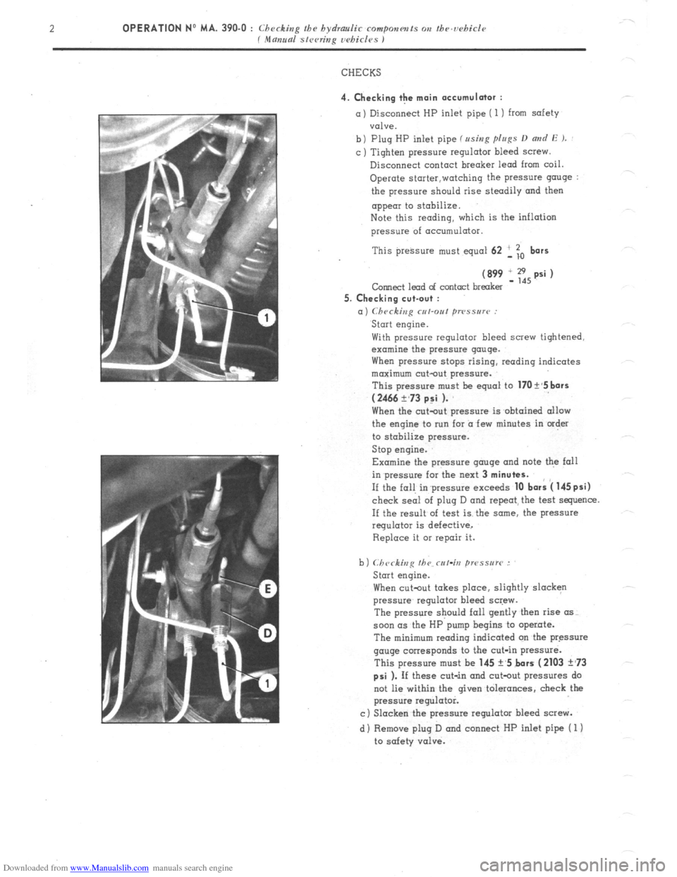
4. Checking the main accumulator : a) Disconnect HP inlet pipe ( 1) from safety
valve.
b) Plug HP inlet pipe fusing p[u~s D
and E ). : c ) Tighten pressure regulator bleed screw.
Disconnect contact breaker lead from coil.
Operate storter,watching the pressure g”“ge :
the pressure should rise steadily and then
appear to stobilize.
Note this reading, which is the inflation
pressure of acc”mulator.
This preksure must equal 62 ‘, To
bars
(899 IE,psi) Corned lead of contact breaker
5. Checking cut-out :
a) Checking cut-out ~TPSSU~~~ : Start engine.
With pressure regulator bleed screw tightened,
examine the pressure gauge.
When pressure stops rising, reading indicates
maximum cut-out pressure.
This pressure m”st be equal to
170 t’5 bars
(2466 ?,73 p:i ). When the c”t-o”t pressure is obtained allow
the engine to nrn for a few minutes in order
to stabilize pressure.
Stop engine.
Examine the pressure gauge and note the fall
in pressure for the next 3
minutes. If the fall in’pressure exceeds
10 bark 4 145psi) check seai of plug D and repeat, the test sequence.
If the result of test is the some, the pressure
regulator is defective,
Replace it 01 repair it.
When cutout takes place, slightly slacken
pressure regulator bleed screw.
The pressure should fall gently then rise (IS~.
soon (IS the HP pump begins to operate.
The minimum reading indicated on tbe pressure
gauge corresponds to the cut-in pressure.
This pressure must be 145 +,5 bars
(2103 ?,73
psi ). If these cut-in and cot-out pressures do
not lie within the given tolerances, check the
pressure regulator.
c) Slacken the pressure regulator bleed screw.
d) Remove plug D and connect HP inlet pipe ( 1)
to safety valve.
Page 237 of 394
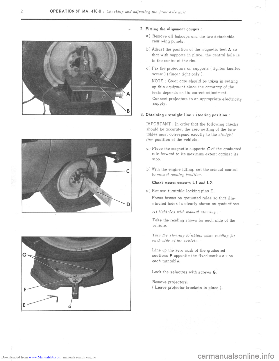
Downloaded from www.Manualslib.com manuals search engine 2: Fitting the alignment gauges :
a) Remove all hubcaps and the two detachable
rear wing panels.
b) Adjust the position of the magnetic feet
A so
that with supports in place, thr central help is
in the centre of the rim.
c ) Fix the projectors on supports ( tighten knurled
screw ) (finger tight only 1.
NOTE Great care should be taken in setting
up this equipment since the accuracy of the
tests depends on its correct adjustment
Connect projectors to on appropriate electricity
SUPPlY.
3. Obtaining S( straight line )I steering position :
IMPORTANT In order that the following checks
should be accurate, the zero setting of the turn-
tables must correspond exactly to the strnifih/
liwv position of the vehicle.
a) Place the magnetic supports C of the graduated
rule forward to its maximum extent against its
stop.
b) With the engine idling, set the manual control
to ,KJWRl n,n,,ir,ji posili, ,,,.
Check measurements Ll and L2.
c)
Removr turntable locking pins E.
Focus beams on grotuoted rules so that illu-
minated index is clearly shown on graduations.
A) Vebirlc,s wilh v~aeunl slvvrin,~
Take the reading shown for each side of the
vehicle.
Line up the zero mark of the graduated
sections
F opposite the fixed mark << a n on
each turntable.
Lock the selectors with screws G.
Remove projectors.
( Leave projector brackets in place ).
Page 239 of 394
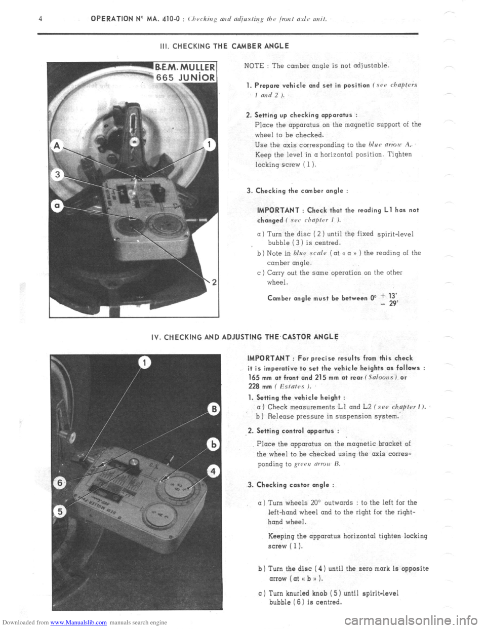
Downloaded from www.Manualslib.com manuals search engine III. CHECKING THE CAMBER ANGLE
NOTE : The camber angle is not adjustable.
1. Prepare vehicle and set in position f src chapfrrs
I and 2 ).
2. Setting up checking apparatus :
Place the apparatus on the magnetic support of the
wheel to be checked.
Use the axis corresponding to the blue mmu A..
Keep the level in a horizontal position. Tighten
locking screw ( 1).
3. Checking the comber angle :
IMPORTANT : Check that the reading Ll has not
changed ( SC<’ rhnprcr I ).
a) Turn the disc (2 ) until the fixed spirit-level
bubble (3 1 is centred.
b) Note in blur scnle (at o a n ) the reading of the
comber rmqle.
c ) Carry out the same operation on the other
wheel.
Comber angle must be between 0’ + 13’ - 29’
IV. CHECKING AND ADJUSTING THE,CASTOR ANGLE
IMPORTANT : For precise results from this check
it is imperative to set the vehicle heights as follows :
165 mm a+ front and 215 mm at rear f Salooss) or
228 mm ( Esfafes ).
1. Setting the vehicle height :
a) Check measurements Ll and L2 f see chapter I ).
b ) Release pressure in suspension system.
2. Setting control opportus :
3. Checking castor angle :
Place the apparatus on the magnetic bracket of
the wheel to be checked using the axis corres-
ponding to grren (ITTOII’ H.
a) Turn wheels 20’ outwards : to the left for the
left-hand wheel and to the right for the right-
hand wheel.
Keeping the apparatus horizontal tighten locking
screw ( 1).
b) Turn the disc ( 4) until the zaro mark is opposite
arrow (at I( b n 1.
c) Turn knurled knob ( 5) until spirit-level
bubble (6) is centred.