weight Citroen CX 1982 1.G User Guide
[x] Cancel search | Manufacturer: CITROEN, Model Year: 1982, Model line: CX, Model: Citroen CX 1982 1.GPages: 394
Page 62 of 394

Downloaded from www.Manualslib.com manuals search engine Op. MA. 100-00
BARRELS AND PISTONS (2350 cc 1
-I
-I
The. Replacement Parts Department only supplies barrel, piston, gudgeon pin and piston ring assemblies in
sets of 4.
. Thickness of barrel base gasket ( uncompressed ) : . . . . . . . . . . . . . .._.._....................................................... 0.1 2 JO.O1O mm
protrusion of barrel ( with gasket uncompressed ) : _..._,_,...,._,............................................................ 0.045 to 0.115 mm
- Variation in weight (pistons, gudgeon pins, and gudgeon pin circlips ) on the same engine : . . . 5 g max.
Page 79 of 394

Downloaded from www.Manualslib.com manuals search engine CARBURATION
OPERATION No MA. 142.00 : Cl~nroricrirtir-s mid .sprrinl ,cnhrcs oi /he cnrh,,wt/or Op. MA. 142.00 1
ENGINE M20/616
I
WEBER CARBURETTORS
34 DMTR 25/200 IDENTIFICATION MARK W 55.00 c:?( 2000 -71 1976
34 DMTR 25/250 IDENTIFICATION MARK W 55-50 cx
2000 7, Id76 -
34 DMTR 25/100 IDENTIFICATION MARK W 54.00 * (.Y X,0(? ;\I/< CO.VIl. - 7 ,976
34 DMTR 25/150 IDENTIFICATION MARK W 54-50 * c-i 2000 /t/K LO\‘,). 7 ,976 -
DESCRIPTION
- Dual choke ,, compound /) type, anti-pollution carburettor with mechonicaliy controlled second choke butterfly
- Mechanically controlled acceleration pump ( cam ) on 1st choke
- Choke on 1st body vacuum assisted cold
start strangler flap
- Fitted damper on idling speed system.
* with incorporated fast idle device
ADJUSTMENTS
DESCRIPTION Primary choke
Venturi bore
Main jets ( removable )
Air corrrction jets
Emulsion tubes
Idling jets [removable ) .._..
Air-bleed idling jets
Acceleration pump injector -high type ( weighted )
Econostot petrol jet ( in cover )
Econostat delaying orifice ( in cover .I
Ball-operated needle valve
Double float : Weights
Positive butterfly opening - Strangler flap fully closed
22 26
115 135
AD 1 ( 195 ) AD 2 ( 180 )
F 30 F 25
50 70
110 70
40
110
100
1 75 “It”
13 1 0.5 g
1.25 i 0.05 mm I
Secondary choke
Page 84 of 394
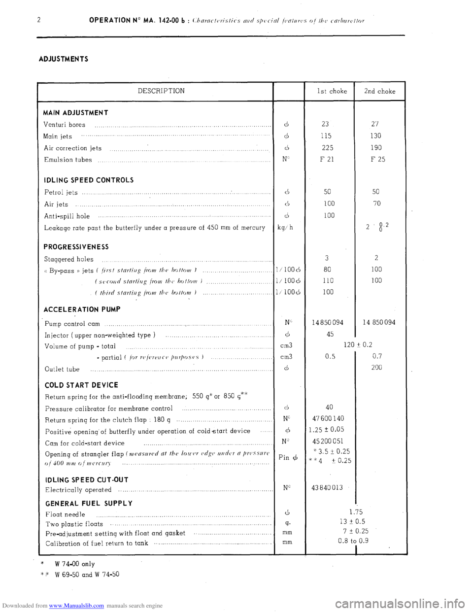
Downloaded from www.Manualslib.com manuals search engine ADJUSTMENTS
DESCRIPTION
1st choke
2nd choke MAIN ADJUSTMENT
Venturi bores
...................................................................................
d 23
27
Main jets ................. ...........................
... ................. ... ....... ...............
cl5 115 130
Air correction jets ..............................................................
d 225 190
Emulsion tubes
...............................................................
......
N’ F 21
F 25 IDLING SPEED CONTROLS
Petrol jets
.......................................................................................
d
50 50
Air jets .....................................................................................
(3
100 70
Anti-spill hole ............... ..............................................
....... ........
d 100
Leakage rate past the butterfly under a pressure of 450 mm of mercury
kg; h 2
$2 PROGRESSIVENESS
Staggered holes 3
2 ...............................................................................
u By-pass )) jets (
/irst stnrtiug /row the ho ttott/ J
100 ............................ 1 / 100 cb 80
( SC~COII~ slnrlirrg I.0Nf the bottom )
...................... l/ 1OOd 110 100
( third stnrfiug [row the bottov~ )
........................... l/100($
100 ACCELERATION PUMP
Pump control cam N”
14 850 094 14 850 094 ...............................................................................
Injector ( upper non-weighted type ) ............................................
d 45
Volume of pump - total
cm3 120 -t 0.2
.......................................................................
- partial ( /or r(‘/vre)~Co /~IIr/wS(‘S ) ................... ...........
cm3 0.5 0.7
Outlet tube
200 ................................................. ....... ...........
............... ... d COLD START DEVICE
Return spring for the anti-flooding membrane; 550 g” or 850 g*‘i;
Pressure calibrator for membrane control ...........................................
(1, 40
Return
spring for the clutch flap
180 g ...............................................
Ni 47 600 140
Positive opening’of butterfly under operation of coldstart device
.... d 1.25 2 0.05
Cam for cold-start device
N” 45 200 051
..............................................................
Opening of strangler flap (mensllrcd dt the loIc,cr c,dgc’ ur/dcJT 0 /lI’(‘.sSlI)‘C * 3.5 i 0.25
() j 4(j(J tr ,),, (J ,,, (Jr(-[,q Pin (b
““4 -t 0.25
..... ... .....................................................
... ...... IDLING SPEED CUT-OUT
Electrically operated NG 43840013 ............................................................................. GENERAL FUEL SUPPLY
Float needle
d 1.35
..................................................................................
Two plastic floats 13 F 0.5 ...................................
............... .............................
g.
7 t 0.25
Pre-adjustment setting with float and gasket ...............................
....... mm
Calibration of fuel return to tank .................................
......................... mm 0.8 to 0.9
1
*
W 74-00 only
* + W 69-50 and W 74-50 .
Page 158 of 394
Downloaded from www.Manualslib.com manuals search engine OPERATION No MA. 210-O : (.h(~~-ki/lg n~lc/ c~tlj~~s/irtg the igrlitiorl Op. MA. 210-O 3
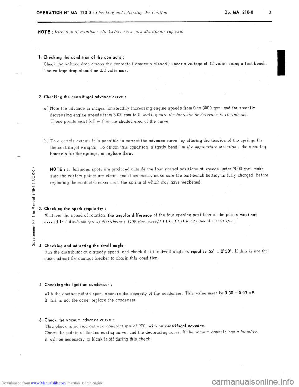
1. Checking the condition of the contacts :
Check the voltage drop across the contacts ( contacts closed ) under a voltage of 12 volts. using a test-bench.
The voltage drop should be 0.2 volts max.
I
2. Checking the centrifugal advance curve :
a) Note the advance in stages for steadily increasing engine speeds from 0 to 3000 rpm. and for steadily
decreasing engine speeds from 3000 rpm to 0, t~/~kjj/$ SII~L’
the irirwasc, or d~,rrc~as~’ is c-o~~ti~ootl.5.
These points must fall within the shaded area of the curve.
b) To a certain extent. it is possible to correct the advance curve, by altering the tension of the springs for
the centrifugal weights To obtain this condition, slightly bend (
iv t/1(, np1)ro/)riotc, ciirectioll J the securing
brackets for the springs, or replace them.
IY NOTE : If luminous spots are produced outside the four normal positions at speeds under 3000 rpm. make
5 sure the contact points are clean and if necessary make sure the test-bench battery is fully charged. before
U replacing the contact-breaker unit. the spring of which may have weakened.
7
co
m
r 3. Checking the spark regularity :
2
Whatever the speed of rotation, the angular difference of the four opening positions of the points must n.ot
3 exceed lo I 21n.xint~lm r/In/ oj distributor : 3250 I./)NI. c,.vcc,pt I)l’(.lit,t.tt~K 525 06X A : 2750
r/m 1,
c
E
!i
a
z 4. Ch k’ ec rng and adjusting the dwell angle :
Run the distributor at a steady speed, and check that the dwell angle is equal ;o 55’ ? 2”30’. If this is not the
case, adjust the contact breaker to obtain this condition.
5. Checking the ignition condenser :
With the contact points open. measure the capacity of the condenser; This value must be 0.30 i 0.03 wF.
If this is not the case. replace the condenser.
6. Check the vacuum advance curve :
This check is carried out at a constant rpm of 200, with no centrifugal advance.
Check the points of the increasing curve. and the decreasing curve. If the vacuum capsule has n hathcr.
it will be necessary to blank it off during this check.
Page 163 of 394
Downloaded from www.Manualslib.com manuals search engine OPERATION No MA. 210-O Q : C.‘/)c,r&iug nnrt nrljtlsliug I110 c~t~~clro~~ic igrliliorl sj’slvnv. Op. MA. 210-O a 3
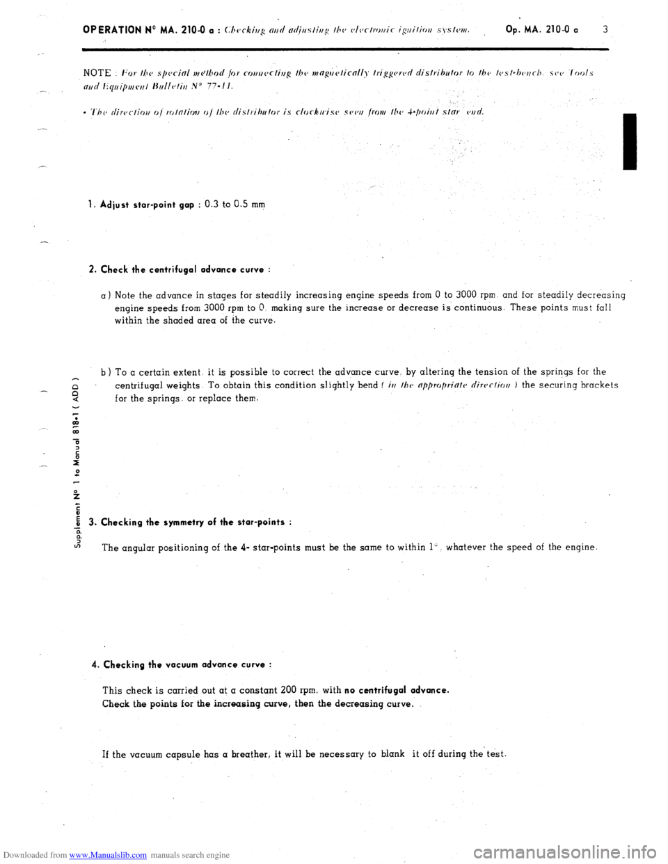
1. Adiust star-point gop : 0.3 to 0.5
mm
2. Check the centrifugal advance curve :
a) Note the advance in stages for steadily increasing engine speeds from 0 to 3000 rpm and for steadily decreasing
engine speeds from 3000 rpm to 0. making sure the increase or decrease is continuous. These points must fall
within the shaded area of the curve.
b ) To a certain extent. it is possible to correct the advance curve. by altering the tension of the springs for the
z centrifugal weights To obtain this condition slightly bend (
irr I~V nppropriate clirvcliou ) the securing brackets
6 for the springs. or replace them.
ot,
43
a
3
E
E 3. Checking the symmetry of the star-points :
-z
0
IFi
The angular positioning of the 4- star-points must be the same to within 1”. whatever the speed of the engine.
4. Checking the vacuum advance curve :
This check is carried out at a constant 200 rpm. with no centrifugal advance.
Check the points for the increasing curve, then the decreasing curve.
If the vacuum capsule has a breather, it will be necessary to blank it off during the’test.
Page 243 of 394
Downloaded from www.Manualslib.com manuals search engine a OPERATION N’ MA. 410-O : (./~rrkiq N,,I/
VI. CHECKING AND ADJUSTING THE STEERING GEOMETRY
The crossmember supporting the steering has slots at its fixing point on the front subframe.
Any vertical movement of this crossmember alters the steering geometry.
WARNING
This operation is only to
be carried out in certain ccxses such as
-accidental impact, with repercussions on the steering system.
-work on the vehicle entoiling removal of steering crossmember.
- vehicle with poor
road stability ( p oar stright-line stability) 01 with excessive tyre weor.
CHECKING
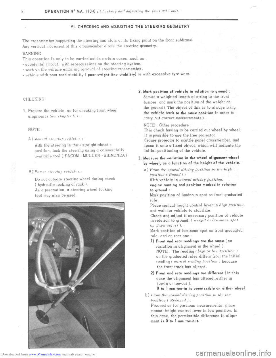
1, Prepare the vehicle. as for checking front wheel
alignment ( Srr ~ho/,lvr
V I.
NOTE
A ) \In,,unl ~fi~<,r;,,~ I chiclvs :
With the steering in the /< straightahead 1)
position. lock the steering using CI commercially
available tool ( FACOM _ MULLER -WILMONDA)
B) PO,, P)’ \,r,rr;ng r’cliirl<,.s :
Do not actuate steering wheel during check
( hydraulic locking of rock 1.
As a precaution. a steering wheel iocking
tool may also be
used. 2. Mark position of vehicle in relation to
ground :
Secure a weighted length of string to the front
bumper. and
mark the position of the weiqht on
the ground ( The
object of this is to always bring
the vehicle
bock to the some position in order to
carry out correct measurements 1.
NOTE Other procedure
This check having to be carried out wheel hy wheel.
it is possible to use the free projector.
Secure projector to scuttle panel crossmemher, and
focus it onto a fixed object, which will indicate the
initial positioning of the vehicle.
3. Measure the variation in the wheel alignment wheel
by wheel, ds o function of the height of the vehicle.
a) From Ihc m~nwnl rlri,:ir,g posi/ior, lo /hc hi@
posilio,, f ftouad 1 :
With vehicle in mwmal rlriving position.
engine running ond position marked in relation
to groond :
Mark position of luminous spot on front graduated
rule.
Place m’anual height control lever in hi&
posilirrrl.
and wait for vehicle to stabilize.
Check and adjust if necessary position of vehicle
in relation to ground. ( II
eight 01 Inmbrous spol
ou /i wd 0 hit,< I J.
Mark position of luminous spot on front graduated
rule. and on rear one
1) Front and rear readings ore the some (no
variation in alignment in the wheel 1.
NOTE : The reading f I,i$ or lorr posilios J
on the qroduated rules differs from the initial
reading f non,,nl >r,nrlinl:
position J because
the front track has altered.
2) Front and rear readings ore different ( in this
case the alignment has oltered,.either in
toe-in or toe-out ).
0 to 1 mm toe-in is permissible on either wheel
b) ,:rr ,,I, /bv IIDIINRI hi&g ,,osi,;orr lo ,I,<, lo,,
posiliov f Hrlmuad ) :
Proceed OS for previous measurements, place
manual height control lever in low position. In
this case. the permissible difference in oliqn-
ment
is O.to 1 mm toe-out.
Page 258 of 394
Downloaded from www.Manualslib.com manuals search engine 2 OPERATION No MA. 430-O : ~hwki~zg nrtd nrijustittg the suspwrsiott ntd its cotttrol
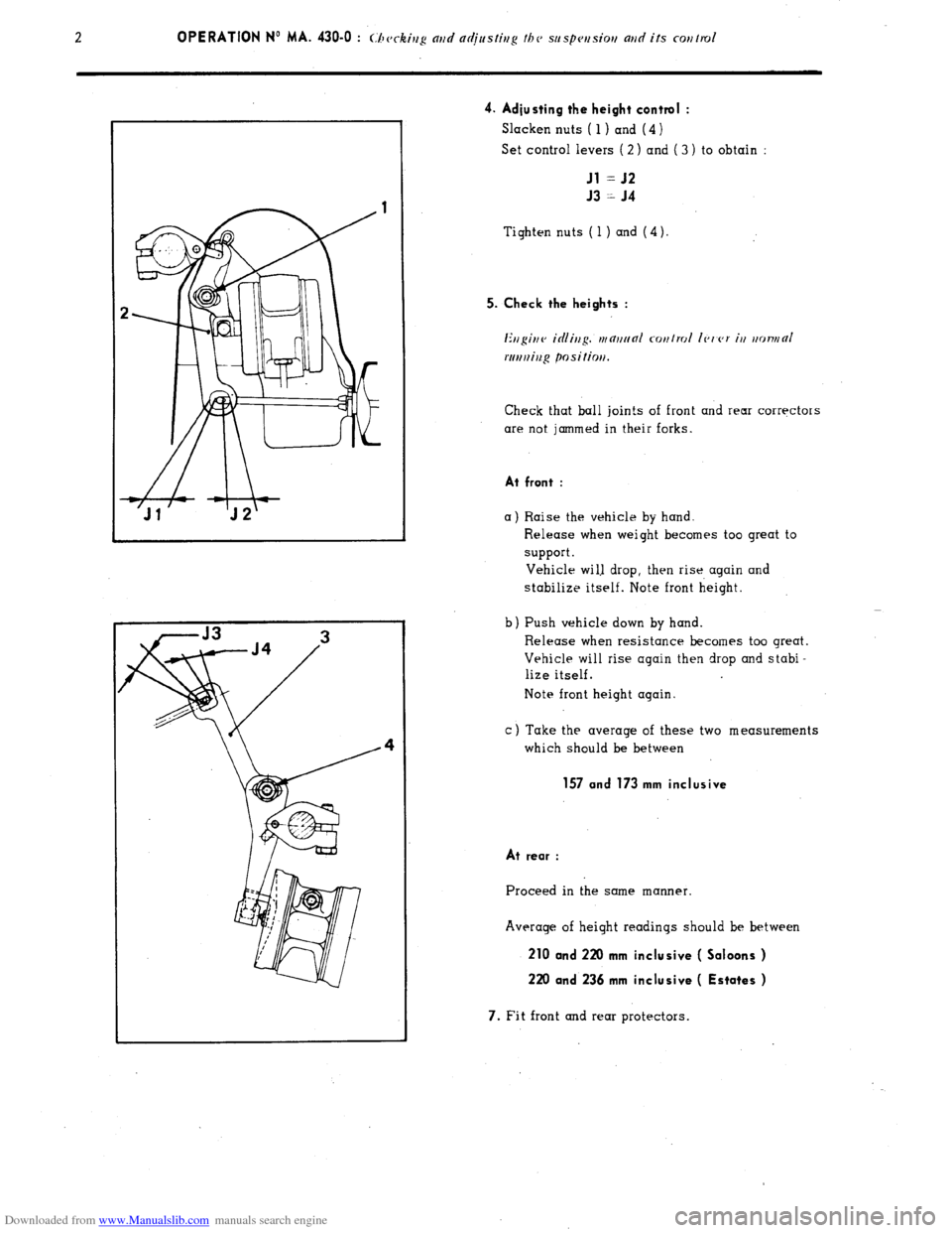
4. Adjusting the height control :
Slacken nuts ( 1) and (4 )
Set control levers ( 2 ) and ( 3 ) to obtain :
Jl = J2
J3 = J4
Tighten nuts ( 1 ) and (4).
5. Check the heights :
Ertgittv icilittg. tttnttt~nl cotttrol Ic,t’c,r itt ttotvttO/
rtrrtttiug positiott.
Check that ball join!s of front and rear corrqctors
are not jammed in their forks.
At front :
a) Raise the vehicle by hand.
b Release when weight becomes too great to
support.
Vehicle wi1.l drop, then rise again and
stabilize itself. Note front height.
Push vehicle down by hand
Release when resistance becomes too great.
Vehicle will rise again then drop and stabi-
lize itself.
Note front height again.
c) Take the average of these two measurements
which should be between
157 and 173 mm inclusive
At rear :
Proceed in the same manner.
Average of height readings should be between
210 and 220 mm inclusive ( Saloons )
220 and 236 mm inclusive ( Estates )
7. Fit front and rear protectors.
Page 268 of 394
Downloaded from www.Manualslib.com manuals search engine d
m
.-
0
2
f Op. MA. 440-00
7 -
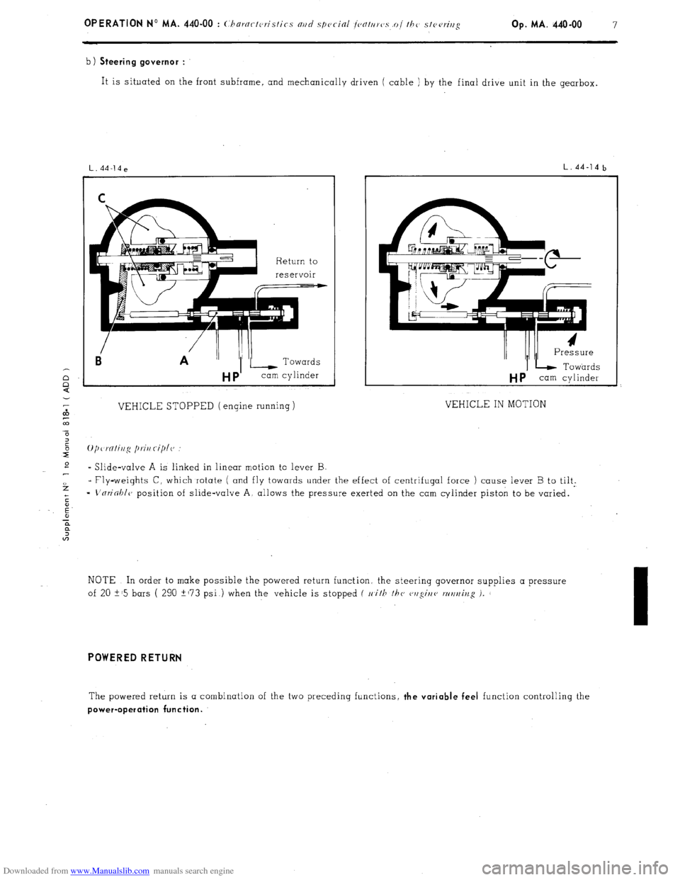
b) Steering governor :
It is situated on the front subframe, and mechanically driven ( cable ) by the final drive unit in the gearbox.
Ei A ”
VEHICLE STOPPED (engine running)
L.44-14b
I/ /II I Pressure
IL Towards
HP cam cylinder
VEHICLE IN MOTION
* Slide-valve A is linked in linear motion to lever B
- Fly-weights C, which rotate ( and fly towards under the effect of centrifugal force ) cause lever B to tilt.
=
L'nrioblc, position of slide-valve A, allows the pressure exerted on the cam cylinder piston to be varied.
NOTE In order to make possible the powered return function. the steerinq governor supplies a pressure
of 20 i-15 bars ( 290 +173 psi ) when the vehicle is stopped f 11
i/F /hc cwgir/e wt/t~iv.g i.
I
POWERED RETURN
The powered return is a combination of the two preceding functions, the variable feel function controlling the
power-operation function.
Page 361 of 394
Downloaded from www.Manualslib.com manuals search engine AIR-CONDITIONING
CHARACTERISTICS AND SPECIAL FEATURES OF THE AIR-CONDITIONING SYSTEM
The air-conditioning system includes the refrigeration and the heating of the air drawn into the passenger compart-
ment. REFRIGERATION
This allows the air in the passenger compartment to be cooled, while at the same time reducing its dampness (and
therefore the misting up of the glass ) HEATING
It is of the (( FROID - 15)) or (( FROID - 20 )) type
1 The air is blown around the channels of a radiator supplied by water from the engine cooling system.
&
co
5
3
t
E REFRIGERATION
E I. CHARACTERISTICS
ASPERA FRIGO type HG 700 or
Compressor
1 .
SANKYO * type SD 508
De-watering tank . SINGER
Condenser _.. ._..: _._...... . . . . . . . . . . . CHAUSSON
Evaporator-blower , SOFICA
Flexible hoses ..,_.,....,............................................................................... STRATOFLEX and RANCO
Refrigerating fluid . R. 12 Weight
of refrigerating fluid _..._.._._._..,_..__.................................................... 1 kg ( 2.2 lbs )
Oil for lubricating compressor TOTAL LUNARIA 25 or SUNISO No. 5
or TEXACO CAPELLA (( E )) grade 500
Quantity of oil for lubricating compressor ,
280 g i.e. a height of 21 to 29 mm
f
CJSCC,~~ ior SANKYO UIVI~WSSO~ J
* Only fitted on vehicles fitted with converter and air-conditioning option.
Page 387 of 394
Downloaded from www.Manualslib.com manuals search engine OPERATION No MA. 852-O : Adius/ir,y I/><, bo,,r,r/ Op. MA. 852-O 1
~.
I. ADJUSTING THE BONNET
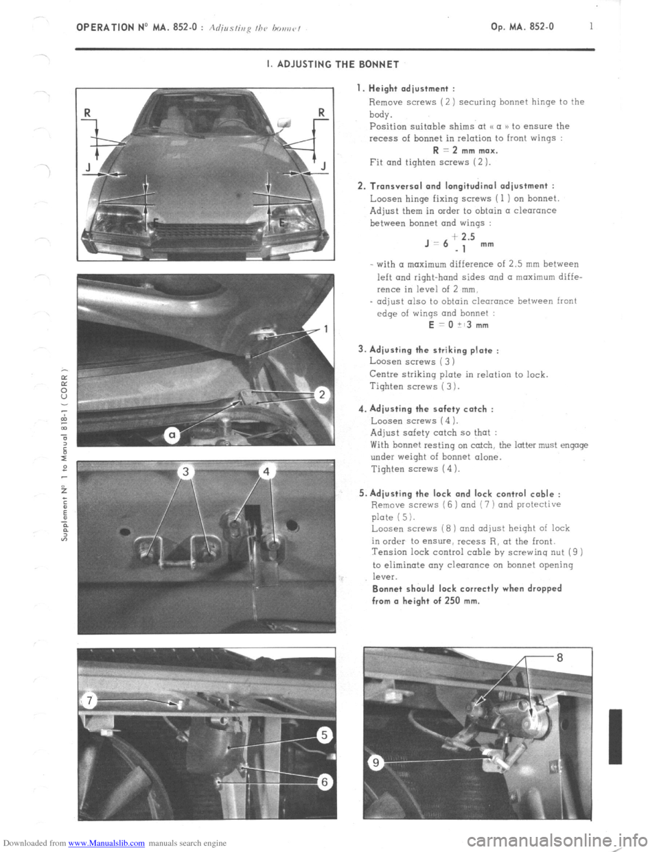
I. Height adjustment :
Remove screws (2) securing bonnet hinge to the
body.
Position suitable shims at u a )) to ensure the
recess of bonnet in relation to front wings : R = 2 mm max.
Fit and tighten screws (2 ). 2. Transversal and longitudinal adjustment :
Loosen hinge fixing screws ( 1 ) on bonnet
Adjust them in order to obtain a clearance
between bonnet and wings : J=6
+ 2.5
-1 mm
- with (I maximum difference of 2.5 mm between
left and right-hand sides and a maximum diffe-
rence in level of 2 mm,
- adjust also to obtain clearance between front
edge of wings and bonnet : E = 0 it3 mm
3. Adjusting the striking plate :
Loosen screws ( 3 )
Centre striking plate in relation to lock.
Tiqhten screws ( 3 ). 4. Adjusting the safety catch :
Loosen screw5 (4 1.
Adjust safety catch so that :
With bonnet resting on catch, the latter must engage
under weight of bonnet alone.
Tighten screws (4 ). 5. Adjusting the lock and lock control cable :
Remove scravs (6 ) and (7 ) and protective
plate (5).
Loosen screws (8) and adjust height of lock
in order to ensure, recess R, at the front.
Tension lock control cable by screwing nut (9 )
to eliminate any clearance on bonnet opening
leV%. Bonnet should lock correctly when dropped
from (I height of 250 mm.